In the vast and intricate world of engineering analysis, precision and reliability are paramount. Whether you’re designing a complex aerospace component, optimizing an oil & gas pipeline, or analyzing the biomechanics of a joint, the underlying mathematical and computational models must accurately reflect physical reality. One subtle yet profoundly impactful concept that engineers often encounter, particularly in simulations like Finite Element Analysis (FEA) and Computational Fluid Dynamics (CFD), is non-orthogonality.
Far from being a mere academic curiosity, non-orthogonality can significantly influence the accuracy, stability, and convergence of your simulations. Understanding it, identifying its presence, and knowing how to mitigate its effects is crucial for any engineer aiming for robust and reliable results.

Image courtesy of User:Cflm001 (Wikimedia Commons).
Understanding Non-Orthogonality: The Core Concept
To truly grasp non-orthogonality, let’s briefly revisit its counterpart: orthogonality.
What Exactly is Orthogonality? (A Quick Refresher)
In simple terms, two vectors or axes are orthogonal if they are perpendicular to each other, forming a 90-degree angle. Think of the standard X, Y, Z axes in a Cartesian coordinate system – they are mutually orthogonal. This property is highly desirable in many engineering contexts because it simplifies calculations and allows for the independent analysis of components.
- Decoupling: Orthogonal components act independently, meaning a change in one does not directly affect the others along their respective axes.
- Simplicity: Mathematical operations (like projections or dot products) become straightforward.
- Efficiency: Algorithms often perform better when dealing with orthogonal systems.
The Flip Side: What is Non-Orthogonality?
Non-orthogonality occurs when vectors, axes, or components are *not* perpendicular to each other. Instead, they form angles other than 90 degrees. While sometimes inherent to a problem’s geometry or physics, it often arises as an artifact of numerical discretization, particularly in meshing for FEA and CFD.
Imagine pushing a box. If you push it perfectly horizontally (orthogonal to gravity), its vertical motion due to your push is zero. If you push it at an angle (non-orthogonal), your push has both horizontal and vertical components, making the analysis more complex due to coupling.
Where Non-Orthogonality Appears in Engineering
Non-orthogonality is not confined to a single domain. It surfaces in various engineering disciplines, each with its unique implications.
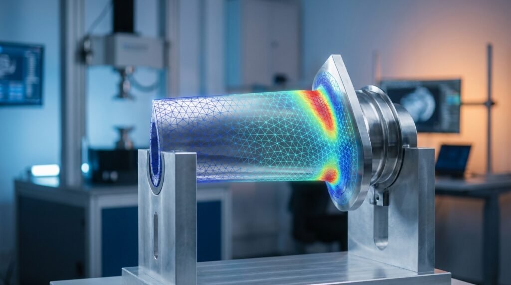
Computational Fluid Dynamics (CFD) & Finite Element Analysis (FEA)
This is arguably where non-orthogonality makes its most prominent and critical appearance: through mesh quality. In both CFD and FEA, the continuous domain of an engineering problem is discretized into a finite number of elements or control volumes. The shape and arrangement of these elements directly impact the accuracy and stability of the numerical solution.
- Skewness: A common metric for non-orthogonality in meshes. High skewness indicates that the angle between element faces and the vector connecting cell centers deviates significantly from 90 degrees.
- Aspect Ratio: While not direct non-orthogonality, high aspect ratio cells (very long and thin) in regions of rapidly changing flow or stress can also introduce numerical errors similar to those caused by non-orthogonality.
- Impact: Poor mesh quality due to non-orthogonality can lead to spurious oscillations, non-physical results, slower convergence rates, or even outright divergence of the solution. This is especially true in CFD where the convection terms are sensitive to grid alignment.
- Tools: Software like ANSYS Fluent/CFX, OpenFOAM, Abaqus, and ANSYS Mechanical extensively use mesh quality metrics to identify and address non-orthogonal elements.
Structural Mechanics & Dynamic Analysis
Non-orthogonality can manifest in structural problems in several ways:
- Non-Orthogonal Loads or Boundary Conditions: When forces or constraints are applied at angles that do not align with the primary axes of the structure or its elements, their components are inherently non-orthogonal.
- Coupled Mode Shapes: In vibration analysis, mode shapes are ideally orthogonal. However, for complex structures, especially those with non-symmetric stiffness or mass distributions, mode shapes might exhibit coupling, where a single mode involves significant deformation in multiple directions that aren’t perfectly aligned with principal axes.
- Anisotropic Materials: Materials whose properties (e.g., stiffness) vary with direction (e.g., composites) inherently introduce non-orthogonality into the material response, complicating stress and strain analysis.
- Tools: Abaqus, ANSYS Mechanical, and MSC Nastran are designed to handle complex load cases and material models, often employing advanced solvers to manage these non-orthogonal interactions.
Coordinate Systems & Transformations
In CAD-CAE workflows, defining local coordinate systems that are non-orthogonal can simplify the input for certain features but complicates transformations back to global Cartesian systems. This is particularly relevant in areas like robotics or biomechanics where complex geometries and motions are analyzed, often using specialized joint or body-fixed coordinate systems.
The Challenges & Consequences of Non-Orthogonality
Ignoring non-orthogonality can have severe ramifications for your engineering analysis:
- Increased Numerical Errors: In CFD, non-orthogonal meshes can lead to numerical diffusion (smearing out sharp gradients) or dispersion (oscillations). In FEA, it can reduce the accuracy of stiffness matrix calculations.
- Slower Convergence or Divergence: Numerical solvers often struggle to converge when faced with highly non-orthogonal elements, sometimes leading to excessively long computation times or complete divergence without a solution.
- Difficulty in Interpreting Results: Spurious results or physically unrealistic phenomena can emerge, making it challenging to extract meaningful insights from the simulation.
- Computational Cost: To compensate for poor mesh quality, engineers might be forced to use finer meshes everywhere, leading to significantly higher computational demands.
Practical Strategies for Managing Non-Orthogonality
Addressing non-orthogonality is a multi-faceted task, often requiring a combination of good practice, intelligent meshing, and robust solver settings.
Mesh Quality Control (FEA/CFD)
This is your first line of defense against non-orthogonality in simulations.
- Understand Metrics: Familiarize yourself with key mesh quality metrics like orthogonal quality, skewness, aspect ratio, and warpage. Each software package will have its specific definitions and recommended thresholds.
- Set Quality Targets: Define acceptable minimum and maximum values for each metric based on your simulation type (e.g., steady-state, transient, turbulent, linear elastic). For instance, in CFD, an orthogonal quality below 0.1 is often considered critical.
- Local Refinement and Smoothing: Focus on regions with high gradients or complex geometries. Use techniques like local mesh refinement, inflation layers near walls (in CFD), and mesh smoothing algorithms to improve element quality without excessively increasing cell count.
- Remeshing: For very problematic geometries, a complete remesh with different meshing strategies (e.g., hexahedral instead of tetrahedral, polyhedral meshes in CFD) might be necessary.
- Adaptive Meshing: In some advanced simulations, adaptive meshing techniques automatically refine the mesh in regions where errors are high, often improving orthogonality in critical areas.
Handling Non-Orthogonal Loads & BCs (Structural)
When loads or boundary conditions are inherently non-orthogonal:
- Component Decomposition: Decompose forces or displacements into components aligned with the global Cartesian axes or a more suitable local orthogonal system. Most FEA software allows this directly.
- Transformation Matrices: For complex transformations between non-orthogonal and orthogonal systems, leverage transformation matrices. This is often automated within CAD/CAE tools but understanding the underlying math helps in troubleshooting.
Verification & Sanity Checks
Even with good meshing, verification is key to ensuring your solution’s robustness against non-orthogonality effects.
- Grid Convergence Study: Perform simulations on multiple meshes (coarse, medium, fine). If the results change significantly between the medium and fine meshes, non-orthogonality or other mesh-related issues might still be present.
- Sensitivity Analysis: Vary critical parameters (e.g., boundary condition angles, material properties) and observe the sensitivity of your results. Unstable responses might hint at underlying numerical issues related to non-orthogonality.
- Physical Plausibility: Always question your results. Do they make physical sense? Are there unexpected oscillations or localized high stresses in regions where they shouldn’t be?
- Energy Balance Checks: In CFD, checking for mass and momentum conservation. In FEA, ensuring that applied loads balance reactions. Significant imbalances can be a red flag.
- Comparing with Analytical or Experimental Data: Whenever possible, validate your simulation results against simpler analytical solutions or real-world experimental data.
Leveraging Software Capabilities
Modern engineering software offers powerful tools to manage non-orthogonality:
- Built-in Meshers & Checkers: ANSYS Meshing, Abaqus/CAE, Patran, and OpenFOAM’s
checkMeshutility provide comprehensive tools for mesh generation and quality assessment. - Advanced Solvers: Many solvers have specific algorithms designed to improve stability on non-orthogonal grids, though this comes at a computational cost and shouldn’t replace good meshing.
- Scripting for Automation: For repetitive tasks like mesh quality checks or post-processing non-orthogonal results, Python (e.g., with libraries like NumPy, SciPy) or MATLAB scripting can be invaluable. You can automate checks for critical orthogonal quality thresholds and flag problematic regions.
Practical Workflow: Tackling Non-Orthogonal Meshes in CFD
Let’s walk through a typical workflow for addressing non-orthogonal meshes in a CFD context, a common scenario for many engineers.
- Initial Mesh Generation & Quality Assessment:
- Generate an initial mesh based on your geometry and desired resolution.
- Run a mesh quality report in your chosen software (e.g., ANSYS Fluent Meshing, OpenFOAM’s
checkMesh). - Focus specifically on metrics like Orthogonal Quality and Skewness. Identify the minimum orthogonal quality and maximum skewness.
- Identify Problematic Regions:
- Visualize the mesh and color-code elements by their orthogonal quality. This quickly highlights areas where the mesh is poor (often sharp corners, thin sections, or complex intersections).
- Pay attention to boundaries, especially near walls where boundary layer resolution is critical.
- Refinement & Smoothing Strategies:
- Local Face/Edge Sizing: Apply finer mesh sizing in the problematic regions.
- Inflation Layers: Ensure sufficient inflation layers (prism or hexahedral elements) are generated near walls with appropriate growth rates to capture boundary layer physics while maintaining good orthogonal quality.
- Mesh Smoothing: Apply mesh smoothing algorithms to relax elements and improve angles. Be careful not to over-smooth, which can distort features.
- Polyhedral Meshes: If available (e.g., in Fluent, OpenFOAM), consider polyhedral elements. These often offer better orthogonal quality than tetrahedral meshes for complex geometries due to their many faces.
- Splitting/Merging: Manually split large elements or merge small ones if your software allows.
- Iterative Improvement:
- After applying adjustments, regenerate the mesh (or just the affected regions) and re-run the quality report.
- Repeat steps 2 and 3 until the minimum orthogonal quality and maximum skewness are within acceptable limits for your application. This might involve several iterations.
- Verification of Impact:
- Once your mesh quality is satisfactory, perform a grid convergence study to quantify the impact of the improved mesh. Run the simulation on the initial “poor” mesh and the final “good” mesh to observe differences in key results (e.g., drag coefficient, pressure drop, stress concentration).
- Document your mesh quality metrics and the convergence behavior for future reference.
For complex geometries and advanced meshing challenges, you might find pre-built scripts or templates helpful. EngineeringDownloads.com offers specialized meshing templates and online consultancy to help optimize your CAD-CAE workflows and tackle difficult non-orthogonality issues effectively.
Common Mistakes & Troubleshooting Tips
Even experienced engineers can stumble when dealing with non-orthogonality. Here’s what to watch out for:
Common Mistakes:
- Ignoring Mesh Quality Metrics: Trusting the “visual” appearance of a mesh without checking its numerical quality.
- Assuming Small Non-Orthogonality is Negligible: Even seemingly minor non-orthogonality can accumulate errors, especially in transient or highly convective flows.
- Over-Refining Without Addressing Root Causes: Throwing more elements at a problem without fixing the underlying non-orthogonality can lead to computationally expensive, yet still inaccurate, solutions.
- Solely Relying on Solver Robustness: While modern solvers are robust, they are not a substitute for a good quality mesh.
Troubleshooting Tips:
- Isolate the Problem: If your simulation diverges, try running it on a simplified geometry or a coarser mesh to pinpoint regions of high non-orthogonality that might be causing instability.
- Check Boundary Conditions: Ensure that boundary conditions are applied consistently and that there are no gaps or overlaps that could create mesh singularities.
- Review Solver Settings: Sometimes, adjusting under-relaxation factors (in CFD) or using different discretization schemes can temporarily alleviate issues caused by non-orthogonality, buying you time to improve the mesh.
- Consult Documentation & Forums: Software documentation (e.g., Abaqus Documentation, ANSYS Help) and user forums are invaluable resources for specific error messages related to mesh quality.
Conclusion
Non-orthogonality is an inherent challenge in many areas of engineering analysis, particularly in numerical simulations. However, with a solid understanding of its causes, diligent application of mesh quality control, and rigorous verification practices, engineers can effectively manage its impact. Mastering non-orthogonality isn’t just about getting a simulation to run; it’s about ensuring the accuracy, reliability, and physical fidelity of your engineering insights, ultimately leading to better designs and safer products.
Further Reading
For more detailed information on specific mesh quality metrics and their impact in CFD, refer to the ANSYS Fluent Meshing User’s Guide (or similar authoritative software documentation).