Understanding and predicting fatigue failure is critical for ensuring the longevity and safety of engineering components across industries like aerospace, automotive, and oil & gas. As engineers, we know that static strength is only part of the story; cyclic loading can lead to catastrophic failures even when stresses are below the material’s yield strength. This is where Finite Element Analysis (FEA) becomes an indispensable tool, offering a powerful and efficient way to simulate complex stress states and predict component lifespan.
This comprehensive guide will walk you through the practical aspects of fatigue life prediction using FEA, offering actionable insights and best practices. Whether you’re designing aircraft components, offshore structures, or biomedical implants, mastering FEA for fatigue is a game-changer for structural integrity and reliability.

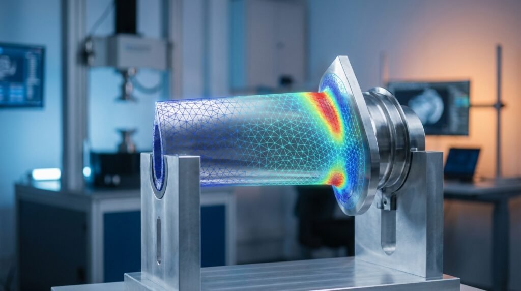
Image courtesy of Wikipedia Commons (CC BY-SA 3.0).
Understanding Fatigue Failure
Fatigue is a progressive and localized structural damage process that occurs when a material is subjected to cyclic or fluctuating stresses and strains. It’s often misunderstood because it can happen at stress levels significantly lower than the material’s static yield strength.
The Basics of Cyclic Loading
Components in operation rarely experience purely static loads. Think of a connecting rod in an engine, a wing in flight, or a bridge under traffic – all are subjected to loads that vary over time. This cyclic nature of stress causes microscopic cracks to initiate, propagate, and eventually lead to sudden fracture, often without warning.
- Stress Amplitude: The range of stress fluctuation is a primary driver of fatigue.
- Mean Stress: The average stress level can significantly influence fatigue life.
- Load Cycles: The number of times the load is applied is directly related to life.
Key Factors Influencing Fatigue
Several critical factors dictate a component’s susceptibility to fatigue failure:
Stress Concentration
Geometric discontinuities (holes, fillets, sharp corners, notches) cause localized stress amplification, making these ‘stress raisers’ prime sites for fatigue crack initiation. FEA excels at identifying and quantifying these areas.
Surface Finish
Surface imperfections, such as scratches, machining marks, or corrosion pits, can act as microscopic stress concentrators, reducing fatigue life. Polished surfaces generally exhibit better fatigue resistance.
Material Properties
The material’s inherent resistance to fatigue is crucial. This is characterized by its S-N (Stress-Number of cycles) curve, which plots stress amplitude against the number of cycles to failure. Some materials, like steel, exhibit an endurance limit below which they can theoretically withstand infinite cycles.
Environmental Factors
Corrosive environments, high temperatures, or even radiation can significantly accelerate fatigue crack growth, leading to what’s known as ‘corrosion fatigue’ or ‘creep-fatigue interaction’.
Why FEA for Fatigue Life Prediction?
FEA offers a powerful, numerical approach to analyze complex geometries and loading conditions that are often intractable with analytical methods alone.
Advantages Over Traditional Methods
While analytical formulas (e.g., beam theory) are excellent for preliminary design and simple cases, FEA provides several distinct advantages:
- Complex Geometries: Accurately models intricate shapes with stress concentrations.
- Realistic Loading: Handles multi-axial, transient, and non-uniform load distributions.
- Material Nonlinearities: Can incorporate plasticity, creep, and other nonlinear material behaviors.
- Virtual Prototyping: Reduces the need for costly and time-consuming physical tests.
- Optimization: Facilitates design iterations to improve fatigue performance efficiently.
Common FEA Software in Fatigue Analysis
Several commercial and open-source FEA packages offer robust fatigue analysis capabilities:
- Abaqus: Known for its powerful nonlinear capabilities, ideal for advanced fatigue and fracture mechanics.
- ANSYS Mechanical: A versatile tool with dedicated fatigue modules, offering both stress-life (S-N) and strain-life (E-N) approaches.
- MSC Nastran/Patran: Widely used in aerospace, strong in linear static and dynamic analysis, with robust fatigue integration.
- OpenFOAM (indirectly): While primarily CFD, structural modules or coupling with other solvers can facilitate fatigue inputs from flow-induced vibrations.
- FE-SAFE, nCode DesignLife: Specialized fatigue analysis software often integrated with major FEA solvers to provide advanced capabilities.
Practical Workflow: Steps for Fatigue FEA
A systematic approach ensures reliable fatigue life predictions. Here’s a typical workflow:
Step 1: Define Your Problem and Loads
Clearly understand the operational environment and expected loads.
Load Types and Cycles
Identify whether the loading is fully reversed, pulsating, or random. Determine the number of cycles or operating hours the component is expected to endure. For instance, an aircraft wing might experience millions of cycles over its lifespan, while a pressure vessel might see thousands of pressurization cycles.
Boundary Conditions
Accurately represent how the component is constrained and supported. Incorrect boundary conditions are a common source of error in any FEA, especially for fatigue where local stresses are paramount.
Step 2: Material Characterization
Accurate material data is non-negotiable for fatigue analysis.
S-N Curves and Endurance Limits
Obtain S-N curves for your material, typically from material handbooks, experimental data, or standards. For steels, the endurance limit (or fatigue limit) is a critical value, often around 0.4-0.5 times the ultimate tensile strength (UTS). Aluminum and other non-ferrous alloys typically do not exhibit a distinct endurance limit.
Illustrative S-N Data (Approximate for a specific Steel Grade)
| Stress Amplitude (MPa) | Cycles to Failure (N) |
|---|---|
| 700 | 103 |
| 500 | 104 |
| 400 | 105 |
| 300 | 106 |
| 250 | >107 (Endurance Limit) |
Goodman, Soderberg, Gerber Criteria
These are mean stress correction theories. They account for the influence of non-zero mean stress on fatigue life. The choice of criterion depends on material type and specific loading conditions. Goodman is common for ductile materials, Soderberg for conservative designs, and Gerber for less conservative, brittle material-like behavior.
Step 3: Geometry and Meshing
The quality of your mesh directly impacts the accuracy of your stress results.
Critical Areas and Mesh Refinement
Identify regions of high-stress concentration (e.g., fillets, holes, sharp corners) and apply fine mesh refinement in these areas. Coarser meshes can be used in regions far from stress risers.
Element Selection
For fatigue, higher-order elements (e.g., quadratic tetrahedral or hexahedral) are generally preferred as they provide more accurate stress predictions, especially in regions of steep stress gradients.
Step 4: Static Structural Analysis
Before diving into fatigue, perform a standard static structural analysis under the peak cyclic load. This step is crucial for identifying stress hotspots and ensuring the basic model setup is correct.
Stress Hotspots
Visually inspect stress contours. The areas with maximum Von Mises stress are typically where fatigue cracks will initiate.
Step 5: Fatigue Analysis Setup
Configure the fatigue specific parameters in your chosen FEA software.
Choosing a Fatigue Algorithm
Decide between Stress-Life (S-N) or Strain-Life (E-N) approaches. Stress-Life is common for high-cycle fatigue (long life, elastic behavior), while Strain-Life is better suited for low-cycle fatigue (short life, plastic deformation).
Load History Definition
Define the load spectrum. This can be constant amplitude, block loading, or complex random loading, often represented by load factors applied to the previously calculated static stress results.
Step 6: Post-Processing and Interpretation
Extract and interpret the fatigue results.
Life Contours and Damage Maps
Visualize the fatigue life (number of cycles to failure) across the component. Damage maps show the accumulation of fatigue damage over time, which is crucial for identifying critical locations and predicting remaining useful life.
Factor of Safety
Calculate the fatigue factor of safety at various locations. A factor of safety greater than 1 indicates that the design can theoretically withstand the applied loads for the specified life, with higher values indicating more conservatism.
Verification & Sanity Checks for Robust Fatigue FEA
Don’t just trust the numbers; rigorous verification is essential for confidence in your FEA results.
Mesh Sensitivity
Perform a mesh convergence study. Rerun the analysis with progressively finer meshes in critical regions and observe if the stress and life predictions stabilize. If results change significantly with finer meshes, your initial mesh was likely too coarse.
Boundary Condition Validation
Double-check that your boundary conditions accurately reflect the real-world constraints. Misplaced constraints can lead to artificially high or low stresses.
Load Equivalence Checks
Ensure that the loads applied in your FEA model represent the actual operating loads in terms of magnitude, direction, and application points. Small errors here can lead to large discrepancies in fatigue life.
Analytical vs. FEA Comparison
For simple stress states, compare FEA results with classical analytical solutions (e.g., stress concentration factors for holes in plates). This builds confidence in your model setup.
Material Data Accuracy
Verify the source and applicability of your S-N curves and other material properties. Using generic data when specific alloy data is available can lead to significant errors.
Common Pitfalls and How to Avoid Them
Even experienced engineers can fall into these traps.
Ignoring Stress Concentrations
A common mistake is to overlook small geometric features or surface conditions that create stress risers. Always scrutinize your stress plots for unexpected hotspots.
Inaccurate Material Data
Using generic S-N curves for a specific alloy can be dangerous. Always strive for material data that closely matches your component’s material, heat treatment, and surface condition.
Insufficient Mesh Refinement
Running with a coarse mesh in critical areas will yield inaccurate stress peaks, leading to overly optimistic (and dangerous) life predictions.
Misinterpreting Results
Understand the limitations of the fatigue theory you are using. For instance, S-N curves are typically based on uniaxial loading; applying them directly to highly multi-axial stress states without correction can be misleading.
Advanced Considerations
Beyond the basics, several advanced topics enhance fatigue analysis capabilities.
Multi-axial Fatigue
When components experience stresses in multiple directions simultaneously, standard uniaxial fatigue theories may not apply. Advanced multi-axial fatigue criteria (e.g., critical plane methods) are needed.
Variable Amplitude Loading
Many real-world components experience loads that vary in amplitude over time. Methods like Miner’s Rule (linear damage accumulation) are used to predict life under such conditions, though more sophisticated approaches exist.
Crack Propagation
Once a crack has initiated, predicting its growth rate is crucial for remaining life assessment and Fitness-for-Service (FFS) assessments (Level 3). Fracture mechanics principles (e.g., Paris’ Law) are employed here, often using FEA for stress intensity factor calculations in tools like Abaqus or ANSYS.
Optimizing Your Workflow with Automation
Repetitive tasks in FEA pre- and post-processing can be automated.
Python and MATLAB for Pre/Post-Processing
Scripting languages like Python and MATLAB are invaluable for automating routine FEA tasks:
- Python: With libraries like NumPy, SciPy, and Matplotlib, Python can automate geometry parameterization, material assignment, boundary condition application, and sophisticated post-processing of FEA results from solvers like Abaqus, ANSYS, and OpenFOAM.
- MATLAB: Excellent for data analysis, signal processing of load histories, and custom plotting of fatigue results. It can also interface with FEA software through APIs.
Automating these steps reduces human error, improves efficiency, and allows for rapid design iterations and sensitivity studies.
Unlock Deeper Insights with EngineeringDownloads.com
Dive deeper into fatigue analysis with our expert resources. From advanced FEA scripts and downloadable project templates for Abaqus or ANSYS to personalized online consultancy, EngineeringDownloads.com provides the tools and expertise you need to tackle your most challenging structural integrity projects. Explore our Python scripting tutorials for automating fatigue workflows or check out our courses on FFS Level 3 assessments.
Further Reading
For more in-depth information on fatigue analysis and FEA best practices, refer to authoritative industry standards and guidelines:
FAQ Section
Here are answers to some common questions about fatigue life prediction using FEA: