Finite Element Analysis (FEA) has become an indispensable tool in modern engineering. From designing aircraft components to simulating biomechanical implants, FEA allows engineers to predict how products will react to various forces, vibrations, heat, and other physical effects. This predictive capability saves immense time and cost, making it a cornerstone of efficient product development.
This guide aims to demystify FEA, providing a practical, engineer-to-engineer approach. We’ll cover the fundamental concepts, walk through a typical workflow, discuss essential verification steps, and offer actionable tips to help you effectively leverage FEA in your projects.

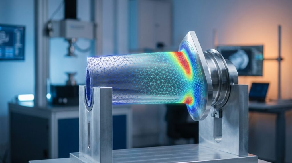
Image Credit: Wikipedia user ‘Tobi_Thoma’ (modified for clarity).
What is Finite Element Analysis (FEA)?
At its core, FEA is a computational method used to predict how a physical object or system behaves under specified conditions. Instead of solving complex differential equations for the entire structure, FEA breaks down a complex geometry into a large number of smaller, simpler elements – hence the term ‘finite elements’. These elements are then assembled, and the behavior of the entire system is approximated by solving equations for each element and combining their results.
Core Concepts Behind FEA
Understanding these fundamental principles is key to conducting effective FEA.
Discretization (Meshing)
- The Big Idea: Instead of analyzing a continuous structure, we divide it into many small, interconnected sub-regions called ‘finite elements’. The collection of these elements forms the ‘mesh’.
- Why it Matters: The accuracy of your FEA results is heavily dependent on the quality and density of your mesh. A finer mesh generally leads to more accurate results but demands more computational power.
Element Types
- Choice is Key: Different element types are suited for different analyses. Common types include 1D (beams, rods), 2D (shells, plates), and 3D (solids).
- Practical Tip: Always choose the simplest element type that accurately represents your geometry and the physics involved to optimize computation time.
Boundary Conditions and Loads
- Defining the Environment: Boundary conditions (BCs) represent how your structure is constrained (e.g., fixed, simply supported) or connected to its surroundings. Loads are the external forces, pressures, temperatures, or displacements applied to the structure.
- Common Mistake: Incorrectly applied BCs or loads are a leading cause of inaccurate FEA results. Always double-check these carefully.
Material Models
- Realistic Behavior: Material models define how a material responds to applied loads (e.g., elastic, plastic, hyperelastic, viscoelastic).
- Consideration: The complexity of your material model should match the expected behavior of your component. For example, a simple linear elastic model might suffice for small deformations, but a non-linear plastic model is crucial for large deformations or permanent yielding.
Why is FEA Indispensable in Modern Engineering?
FEA offers a powerful suite of advantages that have revolutionized product design and validation:
- Design Optimization: Rapidly iterate on designs to achieve optimal performance, weight, and material usage without physical prototyping.
- Cost Reduction: Minimize the need for expensive physical prototypes and testing, especially for complex or large-scale structures.
- Accelerated Prototyping: Bring products to market faster by reducing development cycles.
- Enhanced Safety & Reliability: Identify potential failure points and areas of high stress, leading to more robust and safer designs.
- Virtual Testing: Simulate conditions that are difficult, dangerous, or impossible to replicate physically.
The Practical FEA Workflow: Step-by-Step
A typical FEA simulation follows a structured three-phase approach.
Phase 1: Pre-processing (Setting up the Model)
This is where you define your engineering problem within the FEA software environment.
- CAD Geometry Preparation:
- Import or create your 3D CAD model.
- Simplify geometry by removing unnecessary features (fillets, small holes) that do not significantly impact the analysis but complicate meshing and increase computational cost.
- Clean up geometry: Fill gaps, merge faces, fix free edges.
- Material Properties Definition:
- Assign appropriate material models (e.g., Young’s Modulus, Poisson’s Ratio, Density) to different parts of your geometry.
- Ensure units are consistent across all inputs.
- Meshing Strategies:
- Generate a mesh for your geometry. Start with a coarse mesh to get a quick overview, then refine it in areas of interest (stress concentrations, contact zones).
- Consider using different element sizes for different regions. For example, finer mesh in critical areas and coarser elsewhere.
- Applying Loads and Boundary Conditions:
- Precisely define how the component interacts with its environment. This includes fixed supports, applied forces, pressures, moments, temperatures, or displacements.
- Think about the real-world scenario you’re trying to simulate.
Software Tools for Pre-processing
- Abaqus/CAE: A powerful pre-processor integrated with Abaqus, known for its robust meshing and non-linear setup capabilities.
- ANSYS Mechanical: Features a user-friendly graphical interface for geometry import, meshing, and applying loads/BCs across a wide range of physics.
- MSC Patran: A long-standing pre/post-processor often used with MSC Nastran for complex structural analysis, particularly in aerospace.
Phase 2: Solving (Running the Analysis)
Once the model is fully defined, the FEA solver takes over.
- Solver Types: Choose the appropriate solver based on your problem: linear static, non-linear static, dynamic, modal, thermal, etc.
- Convergence Criteria: For non-linear problems, the solver iteratively finds a solution. Monitor convergence to ensure the solution is stable and accurate. If the solver struggles to converge, it often points to issues in the model setup (e.g., incorrect boundary conditions, poor mesh, severe distortion).
Phase 3: Post-processing (Interpreting Results)
This is where you analyze the output and draw engineering conclusions.
- Contour Plots: Visualize stress, strain, displacement, temperature distributions. Identify maximums, minimums, and gradients.
- Critical Regions Identification: Locate areas of high stress concentration, excessive deformation, or potential failure.
- Reporting: Generate professional reports summarizing findings, including plots, animations, and numerical data.
Verification & Sanity Checks in FEA
Even with advanced software, ‘garbage in, garbage out’ holds true. Rigorous verification is crucial.
Meshing Quality Check
Always inspect your mesh. Check for:
- Highly distorted elements (aspect ratio, skewness, Jacobian values).
- Elements with poor aspect ratios, especially in critical areas.
- Sufficient mesh density in regions of high stress gradients or contact.
Boundary Condition Validation
- Apply simple test loads or check reaction forces to ensure BCs are correctly applied and restraining the model as intended.
- Avoid ‘over-constraining’ (too many fixed degrees of freedom) or ‘under-constraining’ (rigid body motion possible).
Convergence Studies
Perform a mesh convergence study to ensure your results are independent of the mesh size. Run the analysis with progressively finer meshes and plot the critical result (e.g., maximum stress) against mesh density. The results should asymptote to a stable value.
Hand Calculations & Analytical Solutions
For simplified versions of your problem, try to perform hand calculations or use analytical solutions (e.g., beam bending equations, simple stress formulas). Compare these to your FEA results as a first-pass sanity check.
Sensitivity Analysis
Vary key input parameters (e.g., material properties, load magnitudes) within a reasonable range to understand their impact on the results. This helps identify critical parameters and assess the robustness of your design.
Common Mistakes to Avoid
- Poor Mesh Quality: Leading to inaccurate stress predictions, especially at corners or contact surfaces.
- Incorrect Material Properties: Using values that don’t match the actual material or operating conditions.
- Over-constraining / Under-constraining: Implying unrealistic stiffness or allowing the model to fly off due to insufficient restraints.
- Ignoring Singularities: Theoretical infinite stresses at sharp corners or point loads in linear elastic models. Recognize these and interpret results away from such points.
- Misinterpreting Results: Blindly trusting numerical outputs without understanding the underlying physics or limitations of the model.
Choosing the Right FEA Software
The choice of FEA software depends on your specific needs, budget, and industry. Here’s a comparative overview of some popular options:
| Feature | Abaqus (Dassault Systèmes) | ANSYS Mechanical | MSC Nastran / Patran | OpenFOAM (with FEA capabilities) |
|---|---|---|---|---|
| Primary Focus | Advanced non-linear, multiphysics, implicit & explicit dynamics | Comprehensive, broad range of physics, user-friendly | High-end linear structural, aerospace, defense | CFD, but extensible for structural FEA via specific solvers |
| Ease of Use | Moderate to High (powerful, steep learning curve for advanced features) | Moderate (balanced between power and user-friendliness) | Moderate to High (specialized, powerful, requires training) | High (command-line/scripting interface, requires coding knowledge) |
| Industry Adoption | Automotive, Aerospace, Biomechanics, Oil & Gas, Consumer Products | Wide across almost all industries (automotive, energy, electronics) | Aerospace, Defense, Automotive, Heavy Machinery | Academic, R&D, specialized consulting, niche applications |
| Cost Model | High (commercial license) | High (commercial license) | High (commercial license) | Free (Open Source) |
| Automation | Python scripting (Abaqus Scripting Interface) | APDL, Python (PyMAPDL), ACT (ANSYS Customization Toolkit) | Patran Command Language (PCL) | C++, Python scripting (via wrappers or direct code) |
Advanced FEA Applications & Integrations
FEA extends beyond basic static stress analysis into complex interdisciplinary problems.
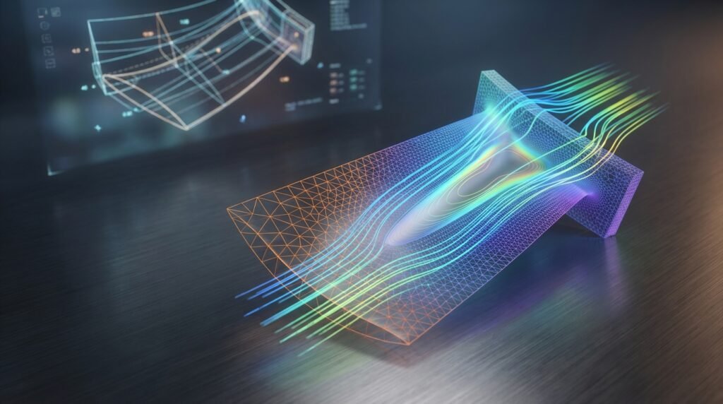
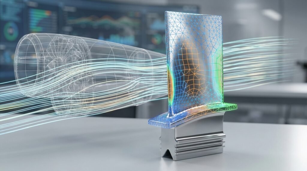
Multiphysics Simulations
Coupling FEA with other physics solvers, such as Computational Fluid Dynamics (CFD), allows for realistic simulations of complex phenomena like Fluid-Structure Interaction (FSI) or thermo-mechanical coupling. Tools like ANSYS Fluent/Mechanical or Abaqus coupled with third-party CFD solvers excel here.
Fatigue Analysis
Predicting the fatigue life of components under cyclic loading is a critical application, especially in aerospace and automotive. FEA results (stress/strain history) feed into fatigue life prediction models to assess durability.
Optimization
Topology optimization, shape optimization, and parameter optimization use FEA to automatically refine designs based on performance criteria and manufacturing constraints. This can lead to significant weight savings and performance improvements.
Scripting & Automation (Python, MATLAB)
Many FEA software packages offer powerful scripting APIs (e.g., Abaqus Python scripting, ANSYS APDL/Python). This allows engineers to:
- Automate repetitive tasks (e.g., post-processing multiple load cases).
- Parametrize models for design exploration or optimization.
- Integrate FEA with other tools (e.g., MATLAB for data analysis).
Looking to streamline your FEA workflow with custom scripts? EngineeringDownloads.com offers downloadable Python scripts and online consultancy to help you automate your CAD-CAE processes.
Practical Tips for Mastering FEA
Becoming proficient in FEA is an ongoing journey. Here are some tips:
- Start Simple: Begin with basic problems that have known analytical solutions to build confidence and understand the software’s behavior.
- Understand the Physics: FEA is a tool; a strong grasp of mechanics, material science, and heat transfer is paramount for accurate interpretation.
- Continuous Learning: Software updates, new methods, and advanced applications emerge constantly. Stay updated through online courses, workshops, and industry forums.
- Network: Engage with other FEA professionals. Sharing experiences and challenging problems can accelerate your learning.
Further Reading / Reference
For a deeper dive into the theoretical underpinnings of the Finite Element Method, consult this resource: Finite Element Method on Wikipedia
Frequently Asked Questions (FAQ)
Question: What is the primary goal of FEA in product design?
Answer: The primary goal of FEA in product design is to predict how a component or structure will behave under various real-world conditions (loads, temperatures, etc.) before physical prototyping. This helps engineers identify potential failure points, optimize designs for performance and durability, reduce material usage, and significantly cut down development costs and time to market.
Question: What’s the difference between linear and non-linear FEA?
Answer: Linear FEA assumes small deformations, linear elastic material behavior, and constant boundary conditions. Calculations are typically faster and simpler. Non-linear FEA, on the other hand, accounts for large deformations (geometric non-linearity), non-linear material behavior (e.g., plasticity), or changing boundary conditions (e.g., contact). Non-linear analyses are more complex, computationally intensive, and require iterative solving, but provide more accurate results for real-world scenarios where these assumptions are violated.
Question: How important is mesh quality in FEA?
Answer: Mesh quality is critically important in FEA. A poor-quality mesh (e.g., highly distorted elements, elements with high aspect ratios, or insufficient density in critical areas) can lead to inaccurate, unstable, or even erroneous results. High-quality meshing ensures that the stiffness matrix of the structure is well-conditioned and that the solution converges accurately, especially in regions of high stress gradients or complex geometry.
Question: Can FEA predict fatigue life?
Answer: Yes, FEA is a crucial first step in predicting fatigue life. It provides the stress and strain distributions (stress/strain history) under cyclic loading conditions. These FEA results are then typically fed into specialized fatigue analysis software or modules (which often integrate with FEA packages) that apply fatigue theories (e.g., stress-life or strain-life approaches) to estimate the number of cycles to failure for a component.
Question: Is FEA difficult to learn?
Answer: Learning the basics of FEA and using commercial software can be relatively straightforward for engineers with a solid background in mechanics. However, mastering FEA for complex, real-world problems – understanding its theoretical underpinnings, correctly interpreting results, performing advanced non-linear analyses, and effectively troubleshooting models – requires dedicated study, practical experience, and continuous learning. It’s a skill that develops over time.
Question: Which industries use FEA most extensively?
Answer: FEA is widely adopted across almost all engineering-intensive industries. Some of the most extensive users include: automotive (crash simulation, component durability), aerospace (structural integrity, lightweighting), biomechanics (implant design, human body modeling), oil & gas (pipeline stress, offshore structures), civil engineering (building and bridge analysis), and consumer products (durability, drop tests, thermal performance).