Additive Manufacturing (AM), often known as 3D printing, has revolutionized how engineers design, prototype, and produce components across various industries. Far beyond just rapid prototyping, AM enables the creation of complex geometries, customized parts, and optimized structures that were previously impossible with traditional subtractive or formative manufacturing methods. This guide delves into the core principles, practical applications, and engineering considerations for leveraging AM effectively.

Image: The first 3D printed concrete pedestrian bridge, located in Gemert, Netherlands. Courtesy of Wikimedia Commons.
Understanding Additive Manufacturing: Beyond the Hype
At its heart, Additive Manufacturing is a process of building a three-dimensional object layer by layer from a digital design. This ‘bottom-up’ approach contrasts sharply with machining (subtracting material) or molding (forming material). For engineers, this fundamental difference unlocks unprecedented design freedom and functional integration.
A Brief History and Evolution
While often seen as a modern marvel, the roots of AM trace back to the 1980s with Chuck Hull’s invention of stereolithography (SLA). Initially a niche technology for rapid prototyping, advancements in materials, process control, and software have propelled AM into mainstream production across aerospace, medical, and automotive sectors. Today, it’s a critical tool for innovation.
Key Additive Manufacturing Processes
The AM landscape comprises several distinct technologies, each suited to different materials and applications. Understanding these differences is crucial for selecting the optimal process.
Material Extrusion (e.g., FDM/FFF)
- How it Works: A thermoplastic filament is heated and extruded through a nozzle, depositing layers onto a build platform.
- Materials: ABS, PLA, PETG, Nylon, PEEK, PEKK.
- Applications: Prototyping, functional parts, tooling, jigs & fixtures.
- Engineering Note: Relatively low cost, wide material choice, but anisotropic properties due to layer adhesion.
Vat Photopolymerization (e.g., SLA, DLP)
- How it Works: A liquid photopolymer resin is selectively cured by a light source (UV laser for SLA, projector for DLP) layer by layer.
- Materials: Various photopolymer resins (tough, flexible, castable).
- Applications: High-detail prototypes, molds, dental applications, jewelry casting.
- Engineering Note: Excellent surface finish and fine features, but typically brittle resins.
Powder Bed Fusion (e.g., SLS, SLM, EBM)
- How it Works: A laser (SLS, SLM) or electron beam (EBM) selectively melts/fuses powdered material layer by layer.
- Materials: Polymers (Nylon, TPU for SLS), Metals (Stainless Steel, Titanium, Aluminum, Nickel Alloys for SLM/EBM).
- Applications: Functional metal parts, complex geometries, aerospace components, medical implants.
- Engineering Note: Produces strong, dense parts, especially with metals, but often requires support structures and careful thermal management.
Binder Jetting
- How it Works: A liquid binding agent is selectively deposited onto a powder bed, bonding particles. The ‘green’ part is then sintered or infiltrated.
- Materials: Metals, ceramics, sand.
- Applications: Large sand molds/cores, full-color prototypes, metal parts (post-sintering).
- Engineering Note: No support structures needed during printing, but post-processing is critical for final strength and density.
Directed Energy Deposition (e.g., LMD, WAAM)
- How it Works: Material (wire or powder) is fed into a melt pool created by a high-energy source (laser, electron beam, or arc) on a substrate.
- Materials: Metals (Titanium, Nickel Alloys, Stainless Steel).
- Applications: Repair of high-value components, adding features to existing parts, large-scale structures.
- Engineering Note: High deposition rates, good for large parts and repair, but lower resolution than powder bed fusion.
Materials for Additive Manufacturing
The rapid expansion of AM is fueled by a growing palette of engineering-grade materials, each with unique properties and processing requirements.
- Polymers: From commodity plastics (PLA, ABS) to high-performance thermoplastics (PEEK, PEKK, ULTEM) and specialized resins.
- Metals: A vast range including stainless steels (316L, 17-4PH), titanium alloys (Ti-6Al-4V), nickel-based superalloys (Inconel 625, 718), and aluminum alloys.
- Ceramics: Technical ceramics like alumina and zirconia, used for high-temperature and wear-resistant applications.
- Composites: Continuous fiber composites (carbon fiber, glass fiber) embedded in polymers, offering enhanced strength-to-weight ratios.
The Design for Additive Manufacturing (DfAM) Mindset
One of AM’s greatest strengths is the freedom it offers, but this requires a fundamental shift in design thinking. DfAM is about leveraging AM’s capabilities while mitigating its limitations.
Key DfAM Principles
- Complexity for Free: Unlike traditional manufacturing where complexity adds cost, AM can often produce intricate geometries with no additional penalty.
- Topology Optimization: Use software (e.g., built into ANSYS Mechanical, Abaqus, or standalone tools) to generate lightweight, organically shaped designs based on load paths and boundary conditions. This is a critical application of FEA in AM.
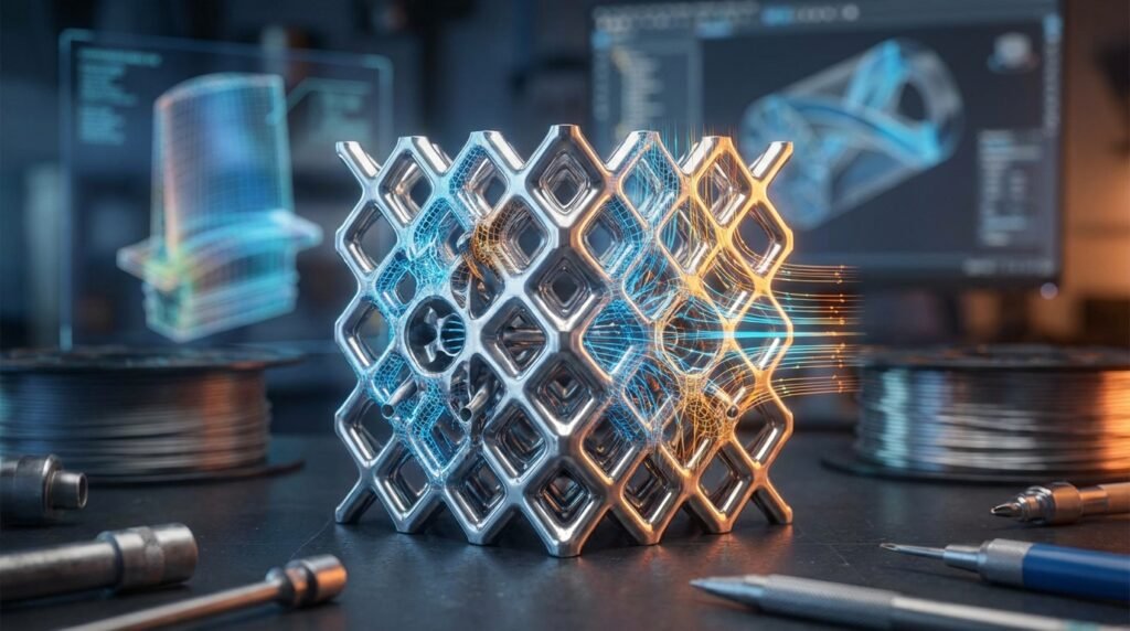
- Lattice Structures: Design internal cellular structures to reduce weight, tailor stiffness, or improve heat transfer without sacrificing overall part performance.
- Part Consolidation: Combine multiple components of an assembly into a single, integrated part, reducing assembly time, part count, and potential failure points.
- Customization and Personalization: Easily produce unique, patient-specific implants in Biomechanics or specialized tools in Oil & Gas.
Practical Workflow: Integrating AM into Engineering Design
Implementing AM effectively requires a structured approach, integrating CAD, CAE, and manufacturing considerations.
- Conceptualization & Design (CAD):
- Begin with a clear understanding of functional requirements.
- Utilize advanced CAD software (e.g., CATIA, SolidWorks, PTC Creo) for initial design, focusing on form, fit, and function.
- Apply DfAM principles from the outset – think organically, consider internal features.
- Design Optimization & Analysis (CAE):
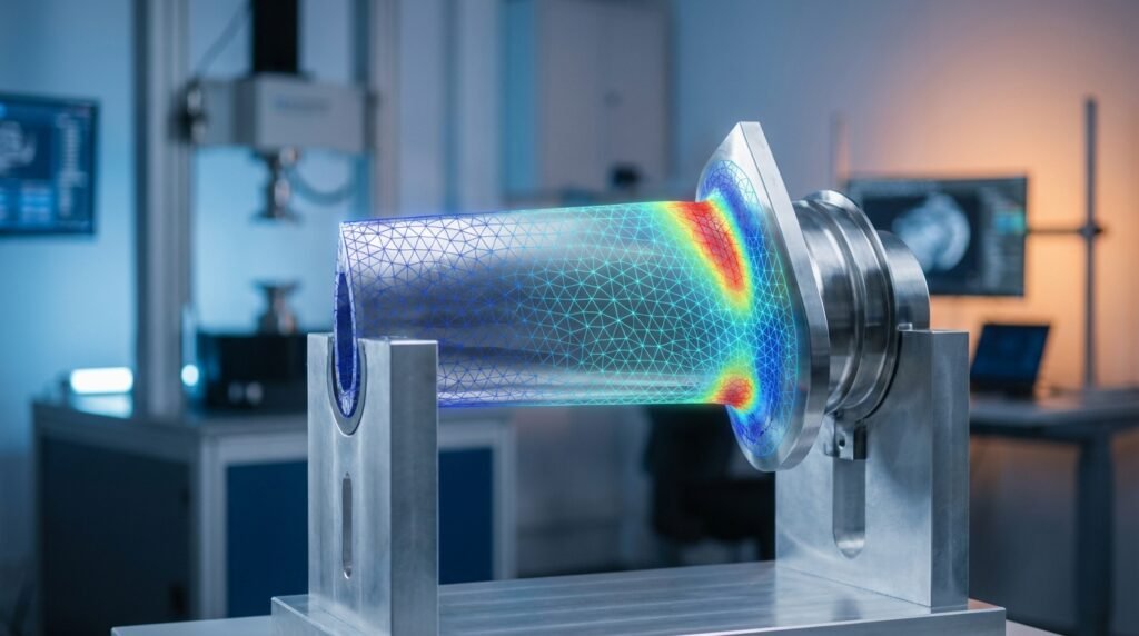
- Perform structural analysis (FEA) to evaluate mechanical performance under anticipated loads. Tools like Abaqus and ANSYS Mechanical are indispensable for stress, strain, fatigue, and buckling analysis, especially for complex AM geometries.
- Consider topology optimization to reduce material and weight.
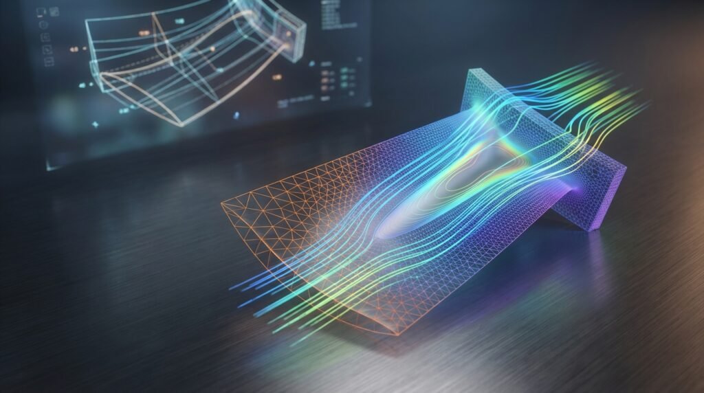
- For parts requiring thermal management, CFD simulations (e.g., ANSYS Fluent/CFX, OpenFOAM) can optimize internal cooling channels or heat sinks.
- Scripting with Python or MATLAB can automate design iterations, parameter studies, and post-processing of simulation results, enhancing efficiency in complex AM workflows.
- Process & Material Selection:
- Based on performance requirements, cost, and lead time, choose the most suitable AM process and material.
- Consider factors like surface finish, mechanical properties, and post-processing needs.
- Build Preparation:
- Convert CAD model to an STL or 3MF file.
- Orient the part optimally on the build platform to minimize supports, reduce build time, and manage anisotropy.
- Add necessary support structures using specialized software.
- Printing & Post-Processing:
- Execute the print.
- Post-processing steps can include support removal, surface finishing (sanding, polishing), heat treatment (stress relief, hot isostatic pressing for metals), and coatings. These steps are crucial for final part quality and performance.
Verification & Sanity Checks in AM Design (Simulation Focus)
Rigorous simulation and verification are critical for reliable AM part performance, especially when targeting high-integrity applications like those in Aerospace or Oil & Gas.
Essential Simulation Considerations for AM
- Material Property Inputs: AM materials often exhibit anisotropic properties. Ensure your FEA models use direction-dependent material data. These can vary significantly from conventionally manufactured equivalents.
- Complex Geometry Meshing: The intricate geometries common in DfAM (lattices, optimized structures) demand high-quality mesh generation. Tools like MSC Patran or the meshing capabilities within Abaqus/ANSYS are key. Perform mesh sensitivity studies to ensure results are independent of mesh density.
- Boundary Conditions (BCs) & Load Cases: Precisely apply BCs and anticipated operational load cases. Consider thermal loads, vibrations, and dynamic impacts.
- Process-Induced Stresses: AM processes, especially metal PBF, introduce residual stresses and distortion due to rapid heating and cooling. Advanced simulation (e.g., using ANSYS Additive Print or Abaqus AM Modeler) can predict and mitigate these effects.
- Convergence Criteria: For non-linear analyses (common with plastics, large deformations, or contact), ensure strict convergence criteria are met. Divergence often indicates an issue with model setup or material behavior.
- Validation & Experimental Correlation: While we don’t perform tests, in a real engineering workflow, simulation results should be validated against physical test data (e.g., tensile tests, fatigue tests of AM coupons). This ensures your models accurately represent AM part behavior.
- Sensitivity Analysis: Understand how variations in design parameters (e.g., lattice cell size, wall thickness) or material properties affect performance. Python or MATLAB scripts can automate running multiple simulation scenarios.
Takeaway: Do not assume AM parts behave identically to conventionally manufactured parts. Comprehensive CAE is non-negotiable.
Additive Manufacturing in Key Industries
AM’s impact spans a diverse range of engineering fields, offering tailored solutions to industry-specific challenges.
Aerospace and Defense
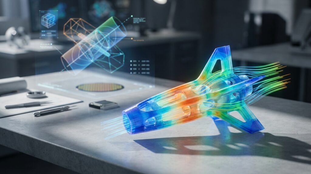
- Applications: Lightweight structural components, complex engine parts (e.g., fuel nozzles), intricate ducting, tooling.
- Benefits: Significant weight reduction (critical for fuel efficiency), part consolidation, enhanced performance, reduced lead times for spare parts.
- Engineering Focus: High-performance metal alloys (Titanium, Inconel), stringent quality control, fatigue life prediction using advanced FEA.
Oil & Gas and Energy
- Applications: On-demand spare parts for remote operations, customized tools for specific well conditions, prototyping complex subsea components, maintenance, repair, and overhaul (MRO).
- Benefits: Reduced inventory, faster field repairs, ability to produce obsolete parts, FFS Level 3 assessment of AM-repaired components (illustrative scenario).
- Engineering Focus: Corrosion-resistant alloys, high-pressure design, structural integrity analysis, material certification for harsh environments.
Biomechanics and Medical Devices
- Applications: Patient-specific implants (e.g., joint replacements, cranial implants), custom prosthetics, surgical guides, dental restorations.
- Benefits: Unmatched customization for improved fit and function, porous structures for osseointegration, rapid production of patient-matched devices.
- Engineering Focus: Biocompatible materials (Titanium, PEEK), precise geometry control, fatigue analysis under cyclic body loads (e.g., using ADAMS for kinematics with FEA inputs).
Automotive and Transportation
- Applications: Rapid prototyping of new designs, tooling for production lines, customized vehicle components, low-volume specialized parts.
- Benefits: Faster design iterations, reduced tooling costs, lightweighting for electric vehicles, supply chain resilience.
Need help navigating complex CAD-CAE workflows for your AM projects? EngineeringDownloads.com offers downloadable scripts, project templates, and online consultancy to streamline your analysis and design processes, leveraging tools like Abaqus, ANSYS, Python, and MATLAB.
Common Mistakes to Avoid in Additive Manufacturing
Even experienced engineers can stumble. Here are typical pitfalls:
- Ignoring DfAM: Simply 3D printing a traditionally designed part often yields suboptimal results. Embrace the design freedom.
- Incorrect Material Selection: Matching material properties to application requirements is paramount. Don’t assume standard material properties apply directly to AM versions.
- Neglecting Post-Processing: Many AM parts require significant post-processing to achieve desired mechanical properties, surface finish, and dimensional accuracy.
- Insufficient Simulation & Verification: Skipping comprehensive FEA/CFD or neglecting validation can lead to costly failures, especially for critical components.
- Overlooking Build Orientation: Suboptimal part orientation can lead to excessive support material, poor surface finish, increased build time, and compromised mechanical properties.
Troubleshooting Common AM Issues (Illustrative Examples)
While specific troubleshooting varies by process, here are common challenges and illustrative solutions:
| Issue | Possible Cause | Illustrative Solution |
|---|---|---|
| Part Warping / Delamination | Differential cooling, insufficient adhesion, internal stresses. | Optimize part orientation, adjust build platform temperature, use brim/raft, implement stress relief post-processing. |
| Poor Surface Finish | Layer height too large, incorrect print speed, insufficient post-processing. | Reduce layer height, fine-tune print speed, increase post-processing (sanding, vapor smoothing). |
| Incomplete Fusion / Porosity (Metals) | Incorrect laser power/speed, insufficient powder, gas entrapment. | Calibrate laser parameters, ensure proper powder flow, consider HIP post-treatment to close internal pores. |
| Dimensional Inaccuracy | Shrinkage, thermal distortion, machine calibration issues. | Calibrate printer, account for material shrinkage in CAD, use advanced simulation to predict distortion. |
The Future of Additive Manufacturing
AM continues its rapid evolution. Expect further advancements in multi-material printing, allowing for functionally graded materials; increased integration of AI and machine learning for process optimization and quality control; and the development of new materials with enhanced properties. As standardization efforts mature, AM will become even more ubiquitous in production environments, driving innovation across engineering disciplines.
Further Reading
For more in-depth technical details on AM standards and terminology, refer to the ISO/ASTM 52900:2021 Additive manufacturing — General principles — Fundamentals and vocabulary standard.