In today’s fast-paced engineering world, simulation projects have become indispensable. From designing safer aircraft to optimizing oil and gas pipelines or developing advanced prosthetics, numerical simulation allows engineers to predict product performance, identify potential issues, and refine designs long before physical prototyping begins. This guide provides a practical, engineer-to-engineer approach to successfully execute your simulation projects, focusing on robust methodologies and common pitfalls to avoid.

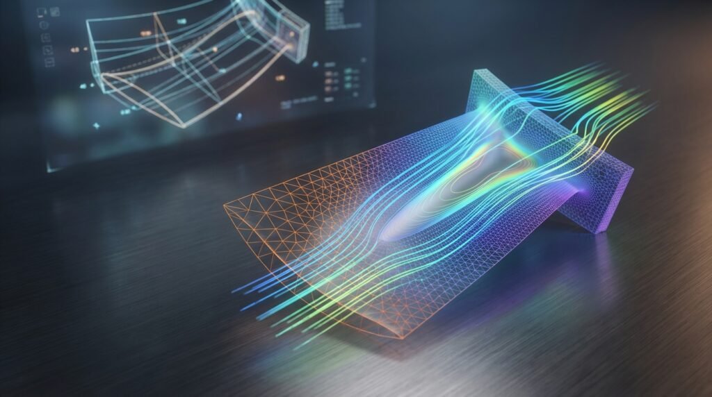
Image: CFD simulation of airflow around a car model. Source: Wikimedia Commons.
The Power of Engineering Simulation Projects
Simulation projects are not just about running software; they represent a fundamental shift in how engineers approach design and analysis. They offer significant advantages:
- Cost Reduction: Minimize the need for expensive physical prototypes and testing.
- Faster Design Iterations: Quickly explore multiple design options and optimize performance.
- Risk Mitigation: Predict failures, assess structural integrity, and ensure compliance with safety standards (e.g., FFS Level 3 assessments for oil & gas).
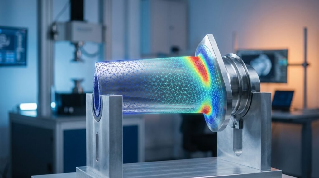
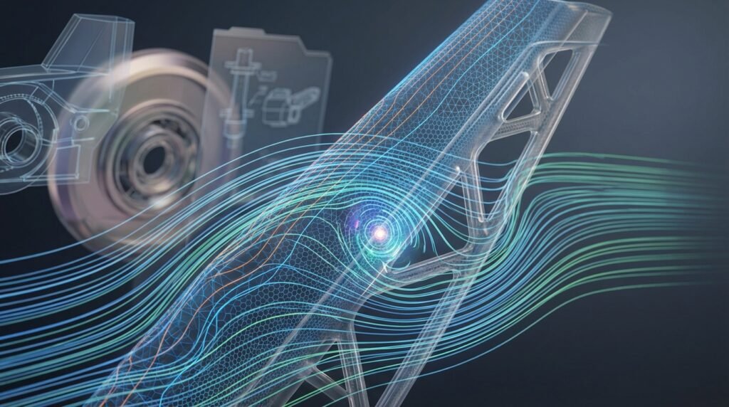
- Deeper Insight: Visualize complex phenomena (stress distribution, fluid flow patterns) that are difficult or impossible to observe physically.
- Performance Optimization: Fine-tune designs for maximum efficiency, durability, and desired characteristics across various engineering disciplines like Aerospace, Biomechanics, and Automotive.
Defining Your Simulation Project
A well-defined project scope is the cornerstone of a successful simulation. Rushing this phase often leads to wasted effort and inaccurate results.
Problem Formulation & Objectives
- Clearly state the engineering problem: What are you trying to understand or solve? (e.g., ‘Determine the stress concentration in a bolted joint,’ ‘Optimize the aerodynamic drag of a component,’ ‘Assess the fatigue life of a critical structural member’).
- Define specific, measurable objectives: What numerical results are you expecting? (e.g., ‘Maximum Von Mises stress less than X MPa,’ ‘Pressure drop across valve less than Y Pa,’ ‘Component life exceeding Z cycles’).
- Identify the system boundary: What is part of your simulation domain, and what is considered external?
Scope Definition & Requirements
Detail the limitations and assumptions of your simulation. This is crucial for managing expectations and interpreting results.
- What phenomena will be included/excluded? (e.g., isothermal flow vs. conjugate heat transfer, linear elastic vs. plastic deformation).
- Required accuracy: How close do your results need to be to reality? This influences mesh density and model complexity.
- Available resources: Computational power, software licenses (Abaqus, ANSYS, OpenFOAM, MSC Nastran), and timeline.
- Output requirements: What kind of plots, data, or reports do you need to generate?
Data Collection & Input Parameters
Gather all necessary data before you begin modeling.
- Material properties: Young’s Modulus, Poisson’s Ratio, Yield Strength, Density, Thermal Conductivity, Viscosity, etc. Ensure you use properties relevant to your operating conditions (temperature, strain rate).
- Geometric data: CAD models (e.g., from CATIA, SolidWorks).
- Loading conditions: Forces, pressures, torques, temperatures, flow rates.
- Boundary conditions: Constraints, fixed supports, inlets/outlets.
Pre-Processing: Setting Up Your Model
This phase is where your conceptual problem is translated into a computational model. It’s often the most time-consuming but critical step.
CAD Geometry Preparation
Your CAD model is the foundation. “Garbage in, garbage out” applies here.
- Simplify unnecessary features: Remove small fillets, holes, and chamfers that won’t significantly affect the global behavior but will drastically increase mesh complexity.
- Imprint and merge surfaces: Ensure proper connectivity for meshing, especially for contact surfaces.
- Defeature for clean mesh: Use CAD tools to repair gaps, overlaps, or sliver faces.
Meshing Strategies
Meshing discretizes your geometry into finite elements. The mesh quality directly impacts solution accuracy and convergence.
- Element Type Selection: Choose appropriate elements (e.g., hex, tet, quad, tri, shell, solid) based on geometry and expected deformation/flow.
- Mesh Density: Refine the mesh in critical areas (high stress gradients, near boundary layers in CFD) and coarsen it where behavior is less critical.
- Mesh Quality Checks: Monitor aspect ratio, skewness, Jacobian, and orthogonality. Poor quality elements can lead to solver errors or inaccurate results. Tools like HyperMesh or the meshing modules in Abaqus/ANSYS are invaluable.
Material Models & Constitutive Laws
Accurately representing material behavior is vital, particularly in non-linear simulations.
- Linear Elastic: Simplest, often suitable for small deformations.
- Plasticity: For metals beyond yield, consider von Mises plasticity, isotropic/kinematic hardening.
- Hyperelasticity: For rubbers and biological tissues (e.g., in Biomechanics projects), use Mooney-Rivlin or Ogden models.
- Fluid Properties: Density, viscosity, thermal conductivity for CFD simulations.
Boundary Conditions & Loads
These define how your model interacts with its environment.
- Constraints: Fixed supports (displacement=0), pinned joints (rotation free).
- Applied Loads: Forces, pressures, moments, prescribed displacements/temperatures, flow rates.
- Common Mistakes: Over-constraining (locking up the model), under-constraining (rigid body motion), applying loads incorrectly, or unrealistic temperature distributions. Always perform a quick sanity check.
Interaction & Contact Definitions
For assemblies, defining interactions between parts is crucial.
- Contact Types: “Hard” contact (no penetration), “soft” contact (allow some penetration).
- Friction: Static and kinetic friction coefficients.
- Bonded Contact: When parts are permanently joined.
Choosing the Right Solver
The choice of solver depends on the physics of your problem. Many modern CAE workflows involve integrating CAD tools like CATIA with solvers like Abaqus or ANSYS.
| Simulation Type | Primary Purpose | Common Tools / Methods | Key Considerations |
|---|---|---|---|
| FEA (Finite Element Analysis) | Structural integrity, stress, strain, deformation, vibration, heat transfer in solids. | Abaqus, ANSYS Mechanical, MSC Nastran, HyperMesh | Material non-linearity, boundary conditions, mesh refinement, contact definition. |
| CFD (Computational Fluid Dynamics) | Fluid flow, heat transfer, mass transport, aerodynamic forces. | ANSYS Fluent/CFX, OpenFOAM, STAR-CCM+ | Turbulence modeling, mesh resolution (boundary layers), convergence criteria. |
| Multibody Dynamics (MBD) | Kinematics and dynamics of interconnected rigid or flexible bodies. | MSC ADAMS, RecurDyn | Joint definitions, contact forces, transient analysis. |
| Fatigue & Fracture | Predicting component life under cyclic loading, crack propagation. | Specific modules in Abaqus/ANSYS, FESafe, FRANC3D | Stress concentrations, material properties (S-N curves), FFS Level 3 assessments. |
Running the Simulation & Post-Processing
Once your model is built, it’s time to run the analysis and interpret the results.
Solver Settings & Convergence Criteria
- Time Stepping: For transient analyses, select appropriate initial and minimum/maximum time steps.
- Solution Controls: Define convergence tolerances for forces, displacements, or residuals. This tells the solver when it has found a stable solution.
- Parallelization: Utilize multiple cores or GPUs to speed up computation for large models.
Monitoring Progress & Troubleshooting
Keep an eye on your simulation’s progress. Most solvers provide log files or real-time monitors.
- Convergence Plots: Check if residuals are dropping for CFD or if equilibrium iterations are converging for FEA.
- Error Messages: Don’t ignore them! They often point to issues with mesh quality, boundary conditions, or material definitions.
- Common Issues: Divergence due to poor mesh, unstable time step, incorrect material properties, or inadequate boundary conditions. Review log files carefully to pinpoint the source.
Data Extraction & Visualization
Post-processing is where you transform raw numerical data into meaningful engineering insights.
- Contour Plots: Visualize stress, strain, displacement, temperature, or velocity fields.
- Vector Plots: Show fluid velocity or heat flux directions.
- Animations: Illustrate transient behavior, vibrations, or flow patterns.
- XY Plots: Extract data at specific locations or over time (e.g., stress vs. time, pressure vs. distance).
- Reporting: Document key findings, assumptions, limitations, and conclusions clearly.
Verification & Sanity Checks: Trusting Your Results
Never take simulation results at face value. A rigorous verification and validation process is essential.
Mesh Sensitivity Analysis
Run your simulation with progressively finer meshes. The results (e.g., maximum stress, lift/drag coefficient) should converge to a stable value. If not, your mesh may still be too coarse.
Boundary Condition Sensitivity
Slightly alter boundary conditions or loads within expected variations. Do your results change dramatically or remain stable? This helps understand the robustness of your model.
Convergence Checks
Beyond solver residuals, ensure the engineering quantities of interest (e.g., total strain energy, reaction forces) have converged. If you’re doing a non-linear analysis, confirm that the iterative solution has achieved acceptable convergence tolerances at each load step.
Hand Calculations & Analytical Solutions
For simplified cases or sub-components, compare your simulation results to basic analytical solutions or well-known engineering formulas. This is a powerful sanity check to catch gross errors.
Experimental Validation (If Data Exists)
The ultimate validation is comparison with experimental test data. While not always feasible for every project, it’s the gold standard for proving your model’s predictive capability.
Common Pitfalls to Avoid
- Ignoring warning messages: Many “warnings” can indicate potential issues down the line.
- Over-modeling: Including too much detail or physics when simpler models would suffice.
- Under-meshing critical areas: Leads to inaccurate peak stresses or velocities.
- Unrealistic material properties: Using generic values when specific, tested data is available.
- Misinterpreting results: Not understanding the fundamental assumptions behind your chosen solver or model.
Practical Workflow for Robust Simulations
Here’s a generalized, iterative workflow for successful simulation projects:
- Define: Clearly state problem, objectives, scope, and gather all data.
- Simplify: Prepare CAD geometry, defeature, and idealize for simulation.
- Mesh: Generate appropriate mesh, focusing on quality and refinement in critical zones.
- Setup: Apply materials, loads, boundary conditions, and contacts. Select solver.
- Solve: Run the simulation, monitor progress, and troubleshoot as needed.
- Post-Process: Visualize results, extract key data, and generate reports.
- Verify & Validate: Perform sanity checks, mesh studies, and compare to analytical/experimental data.
- Iterate: Refine model, mesh, or parameters based on results and verification findings.
Consider integrating Python or MATLAB for automation tasks like parametric studies, batch post-processing, or generating input decks. This significantly boosts efficiency in CAE workflows. For those looking to streamline their simulation workflows or tackle complex problems, remember that EngineeringDownloads.com provides a wealth of downloadable templates, scripts (e.g., Python/MATLAB for automation), and expert online consultancy.
Advanced Topics & Emerging Trends
The field of simulation is constantly evolving:
- Multiphysics Simulations: Combining different physics, e.g., Fluid-Structure Interaction (FSI), thermo-mechanical coupling.
- Optimization: Topology optimization (e.g., in Abaqus/ANSYS) to find optimal material distribution, or shape optimization for performance.
- Fatigue and Fracture Mechanics: Detailed analysis for structural integrity, especially relevant in FFS Level 3 assessments in Oil & Gas.
- AI/ML Integration: Using machine learning to build surrogate models, accelerate simulations, or optimize design parameters.
Conclusion & Key Takeaways
Engineering simulation projects are powerful tools that, when used correctly, can dramatically enhance design, reduce costs, and ensure product reliability. Success hinges on a systematic approach, thorough understanding of the underlying physics, meticulous pre-processing, and rigorous verification. Always question your results, perform sanity checks, and continuously refine your modeling techniques. By following these practical guidelines, you’ll be well-equipped to tackle complex engineering challenges and deliver robust, trustworthy simulation outcomes.