Crack growth is a critical phenomenon that engineers across all disciplines must understand and manage. From the microscopic initiation of a flaw to its macroscopic propagation, the growth of cracks can compromise structural integrity, lead to unexpected failures, and pose significant safety risks. This comprehensive guide dives into the fundamental principles, advanced analysis techniques, and practical strategies for predicting and preventing crack growth in engineering structures.
Whether you’re working on aerospace components, oil and gas pipelines, civil infrastructure, or biomedical devices, mastering crack growth analysis is essential for ensuring the long-term reliability and safety of your designs. Let’s explore how we can tackle this challenge head-on.

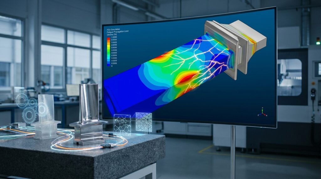
Image: Illustrative diagram of stress concentration around a crack tip.
Understanding the Mechanisms of Crack Growth
Crack growth isn’t a single, uniform process. It’s influenced by various factors, each demanding a specific approach for analysis and mitigation. Recognizing these mechanisms is the first step toward effective prevention.
What Drives a Crack? The Stress Intensity Factor (K)
At the heart of linear elastic fracture mechanics (LEFM) is the Stress Intensity Factor (K). It quantifies the stress field magnitude near the tip of a crack under specific loading conditions. K is crucial because it helps predict when a crack will propagate in brittle materials or when fatigue crack growth will occur.
- Mode I (Opening Mode): Tensile stress perpendicular to the crack plane. This is the most common and often most critical mode for crack growth.
- Mode II (Sliding Mode): Shear stress acting parallel to the crack plane and perpendicular to the crack front.
- Mode III (Tearing Mode): Shear stress acting parallel to the crack plane and parallel to the crack front.
Types of Crack Growth
Fatigue Crack Growth
This is arguably the most prevalent form of crack growth in engineering structures. It occurs due to cyclic loading, even when the applied stresses are well below the material’s yield strength. Fatigue cracks initiate at stress concentrations and grow incrementally with each load cycle.
- Paris Law: The most famous empirical relationship, da/dN = C(ΔK)^m, describes the stable crack growth rate per cycle (da/dN) as a function of the stress intensity factor range (ΔK). C and m are material constants.
- Forman, Walker, and Elber Equations: These are more advanced models that account for factors like stress ratio (R) and crack closure, providing more accurate predictions for varying load conditions.
Environmental Assisted Cracking (EAC)
EAC encompasses several mechanisms where a corrosive environment accelerates crack growth. Common types include stress corrosion cracking (SCC), hydrogen embrittlement (HE), and corrosion fatigue.
- Stress Corrosion Cracking (SCC): Occurs in specific material-environment combinations under static tensile stress. For example, stainless steel in chloride environments or carbon steel in caustic solutions.
- Hydrogen Embrittlement (HE): Hydrogen atoms diffuse into the material, reducing its ductility and making it susceptible to brittle fracture, often under sustained load. Common in high-strength steels.
Creep Crack Growth
At elevated temperatures and sustained loads, materials can deform plastically over time (creep). If a crack is present, it can grow under these conditions, even if the stress intensity is below the fracture toughness at room temperature. This is a critical consideration in power generation and high-temperature process industries.
Why Crack Growth Analysis is Indispensable for Engineers
Ignoring crack growth can have catastrophic consequences. Proactive analysis is not just good practice; it’s often a regulatory necessity.
- Ensuring Safety: Preventing structural failures that could lead to injury or loss of life. Essential in aerospace, nuclear, and civil engineering.
- Optimizing Maintenance & Lifespan: Predicting when a crack might reach a critical size allows for scheduled maintenance, avoiding costly unscheduled downtime and extending asset life.
- Economic Impact: Reducing repair costs, preventing catastrophic equipment failure, and avoiding potential legal liabilities.
- Regulatory Compliance: Many industries (e.g., Oil & Gas with API 579-1/ASME FFS-1, Aerospace with FAA regulations) mandate crack growth assessments for critical components.
Analytical and Empirical Approaches: Practical Tools for Prediction
Before diving into complex simulations, analytical and empirical methods provide foundational understanding and quick estimates.
Remaining Life Assessment (RLA)
RLA uses crack growth laws (like Paris Law) along with initial crack size, loading history, and material properties to estimate how many load cycles or how much time remains before a crack reaches a critical size.
Fitness-for-Service (FFS) Assessments (API 579-1 / ASME FFS-1)
FFS assessments, particularly Level 3, provide a rigorous framework to evaluate the integrity of existing equipment containing flaws (cracks, pitting, wall thinning). These standards specify methodologies for performing crack growth evaluations, often involving detailed FEA. They are widely used in the Oil & Gas and chemical processing industries.
Simulating Crack Growth: The Power of Finite Element Analysis (FEA)
For complex geometries, loading conditions, and material behaviors, FEA becomes an indispensable tool for accurate crack growth prediction.
FEA Fundamentals for Fracture Mechanics
- Linear Elastic Fracture Mechanics (LEFM) in FEA: Used for brittle materials or when plastic zones are small. FEA can directly calculate Stress Intensity Factors (K) using contour integrals or displacement extrapolation methods.
- Elastic-Plastic Fracture Mechanics (EPFM): When significant plasticity occurs at the crack tip. FEA can calculate parameters like the J-integral (energy release rate) and Crack Tip Opening Displacement (CTOD).
- Specialized Elements: Use of quarter-point singular elements around the crack tip or enriched elements (e.g., XFEM – Extended Finite Element Method) to accurately capture the stress singularity.
Practical Workflow for Crack Growth Simulation (FEA)
Performing a crack growth simulation typically follows a structured approach:
- Model Setup:
- Geometry: Import or create the part geometry in your FEA software (e.g., Abaqus, ANSYS Mechanical, MSC Nastran).
- Material Properties: Define accurate material properties, including elastic modulus, Poisson’s ratio, yield strength, and tensile strength. For fatigue, S-N or ε-N curves are needed. For advanced crack growth, da/dN vs. ΔK data is crucial.
- Loads & Boundary Conditions (BCs): Apply realistic operational loads and constraints. This might involve pressure, force, displacement, or thermal loads.
- Crack Definition:
- Initial Crack: Define the initial crack geometry (size, shape, location). This often comes from NDT inspection results.
- Crack Path: For stable crack growth, define potential crack paths or allow the solver to predict them (e.g., using XFEM or VCCT – Virtual Crack Closure Technique).
- Meshing Strategies:
- Refined Mesh: Crucially, the region around the crack tip requires a highly refined mesh to capture stress gradients accurately.
- Spider Web Mesh: A common technique to create a focused, radial mesh around the crack tip.
- Contour Integral Regions: Define regions for calculating K or J-integrals.
- Solver Settings:
- Fatigue Analysis: Use dedicated fatigue modules (e.g., ANSYS nCode DesignLife, Abaqus/Fatigue) for life prediction.
- XFEM: For complex, arbitrary crack propagation without re-meshing.
- VCCT: For simulating crack growth in bonded structures or composites.
- Sub-modeling: For localized crack growth analysis in a small region of a large structure.
- Post-processing & Interpretation:
- K-values/J-integrals: Extract these parameters along the crack front.
- Crack Growth Rate: Plot da/dN vs. ΔK and compare with material data.
- Crack Path & Shape: Visualize how the crack propagates and changes shape.
- Remaining Life: Calculate the predicted number of cycles or time to failure.
Key Software Tools for Crack Growth Simulation
- Abaqus: Renowned for its advanced fracture mechanics capabilities, including XFEM, VCCT, and contour integral methods. Widely used in aerospace and research.
- ANSYS Mechanical: Offers robust fracture tools, including smart crack meshing, fatigue analysis (with nCode DesignLife integration), and J-integral calculations.
- MSC Patran/Nastran: Powerful for large-scale structural analysis and fatigue life prediction, often integrated with specialized fracture mechanics modules.
- Python & MATLAB: Excellent for scripting pre-processing (geometry/mesh manipulation), post-processing (extracting data, plotting da/dN curves), and automating parametric studies. Many custom crack growth algorithms can be implemented and validated.
- OpenFOAM: While primarily CFD, some extensions and custom solvers exist for solid mechanics and fracture, offering open-source flexibility.
Verification & Sanity Checks in FEA Crack Growth
Garbage in, garbage out! Robust verification is crucial for reliable simulation results:
| Check Type | Description | Why it’s Important |
|---|---|---|
| Mesh Sensitivity | Run the analysis with varying mesh densities around the crack tip. Results (K, J-integral) should converge. | Ensures results are independent of mesh size and capture stress gradients accurately. |
| Boundary Condition Influence | Slightly vary BCs or apply simplified analytical loads to ensure they are physically sound. | Incorrect BCs can lead to wildly inaccurate stress distributions and crack behavior. |
| Material Property Impact | Perform sensitivity studies on critical material parameters (e.g., C & m in Paris Law, yield strength). | Quantifies the uncertainty in results due to material data variability. |
| Comparison with Analytical Solutions | For simple geometries (e.g., plate with edge crack), compare FEA K-values with known analytical solutions. | Provides a fundamental validation of your FEA setup for fracture mechanics. |
| Energy Balance & Convergence | Monitor energy balance in the solver output; ensure solution convergence criteria are met. | Indicates the numerical stability and accuracy of the simulation. |
| Physical Interpretation | Visually inspect stress contours, crack paths, and deformations. Do they make physical sense? | Helps catch gross errors and ensures the results align with engineering intuition. |
Common Challenges & Troubleshooting
- Limited Material Data: Obtaining accurate da/dN vs. ΔK curves for specific materials and environments can be challenging. Often requires experimental testing.
- Complex Geometries & Loading: Highly intricate designs and multi-axial, non-proportional loading increase computational cost and modeling complexity.
- Environmental Factors: Integrating the effect of corrosive environments or elevated temperatures accurately into models remains a challenge.
- Computational Cost: Detailed crack growth simulations, especially with XFEM or explicit methods, can be very time-consuming.
- Meshing Pitfalls: Poorly meshed crack tips lead to inaccurate stress fields and unreliable K or J-integral values.
Mitigation & Prevention Strategies
Beyond analysis, engineers must implement practical strategies to prevent and manage crack growth:
- Material Selection: Choose materials with high fracture toughness and good fatigue resistance. For corrosive environments, select corrosion-resistant alloys.
- Design Optimization: Eliminate stress concentrations through thoughtful geometry, fillets, and avoidance of sharp corners. Consider redundant load paths where feasible.
- Surface Treatments: Shot peening, case hardening, and surface coatings can induce compressive residual stresses or improve corrosion resistance, thereby inhibiting crack initiation.
- Inspection & Monitoring: Implement robust Non-Destructive Testing (NDT) programs (ultrasonic, eddy current, radiography) for regular crack detection and sizing. Advanced structural health monitoring (SHM) systems can provide real-time data.
- Repair Techniques: Develop effective repair procedures (welding, patching, composite repair) for managing cracks that are detected during service.
Leveraging EngineeringDownloads.com Resources
Mastering crack growth analysis requires continuous learning and access to the right tools. At EngineeringDownloads.com, you can find valuable resources to enhance your skills:
- Downloadable FEA Templates: Access pre-built Abaqus or ANSYS Mechanical models for common crack growth scenarios, accelerating your learning curve.
- Python & MATLAB Scripts: Enhance your automation for post-processing fracture mechanics data or generating custom da/dN curves.
- Online Tutoring & Consultancy: Need personalized guidance on complex crack growth problems or FFS Level 3 assessments? Our experts offer tailored support to help you navigate challenging projects.
Further Reading
For more in-depth information on Fitness-for-Service assessments and their application in industries like Oil & Gas, explore the official ASME FFS-1 / API 579-1 standard.
Conclusion
Crack growth analysis is a cornerstone of structural integrity engineering. By understanding the underlying mechanisms, leveraging advanced simulation tools like FEA, and applying diligent verification practices, engineers can predict, prevent, and mitigate the risks associated with crack propagation. This proactive approach not only safeguards assets and lives but also contributes to more efficient and reliable engineering solutions across all industries.