When dealing with critical engineering components that exhibit complex flaws, or when routine assessments simply don’t provide sufficient confidence, you need to elevate your game. This is where the Fitness for Service (FFS) Level 3 workflow comes into play. It’s the most rigorous and detailed assessment level, providing unparalleled insights into structural integrity and remaining life prediction. For engineers tackling high-stakes projects in Oil & Gas, Aerospace, or even advanced industrial applications, mastering FFS Level 3 is essential.

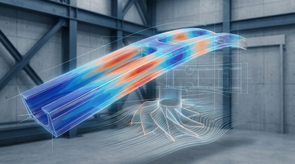
Image: A simplified FFS flow diagram illustrating the assessment process.
What is FFS Level 3 and Why is it Crucial?
Fitness for Service (FFS) assessments, primarily guided by standards like API 579-1/ASME FFS-1, provide methodologies to evaluate the integrity of components containing flaws. These assessments determine if a component can continue to operate safely for a specified period.
FFS assessments are categorized into three levels, each increasing in complexity and accuracy:
- Level 1: Screening Assessment – Simple, conservative, often based on charts and tables.
- Level 2: Intermediate Assessment – More detailed calculations, less conservative than Level 1, requiring specific engineering calculations.
- Level 3: Advanced Assessment – The most comprehensive, involving detailed stress analysis (often using Finite Element Analysis) and advanced fracture mechanics. It’s employed when Level 1 or 2 are too conservative, inapplicable, or when higher accuracy is mandated due to critical component function or complex flaw geometries.
FFS Level 3 is crucial for:
- Extending the life of high-value assets.
- Optimizing repair/replace decisions.
- Ensuring safety in critical infrastructure where failures are unacceptable.
- Dealing with complex loading conditions, material degradation, and intricate flaw interactions.
When to Elevate to an FFS Level 3 Assessment
Moving beyond Level 1 or 2 often signals increased complexity or a need for refined results. Consider Level 3 when:
- Level 1 or 2 criteria are not met, but you suspect the component is still safe.
- Flaw geometries are complex (e.g., interacting flaws, non-planar cracks).
- Loading conditions are complex (e.g., cyclic, thermal gradients, multiaxial).
- Material behavior is non-linear or requires advanced constitutive models.
- The consequence of failure is extremely high, demanding maximum confidence.
- You need to accurately predict remaining life under specific operational profiles.
The FFS Level 3 Workflow: A Step-by-Step Guide
Performing an FFS Level 3 assessment is an iterative and systematic process. Here’s a breakdown:
1. Data Collection and Initial Assessment
- Flaw Characterization: Detailed non-destructive examination (NDE) data (ultrasonic testing, radiography, eddy current) to precisely define flaw type, size, location, and orientation.
- Material Properties: Accurate mechanical properties (yield strength, tensile strength, fracture toughness KIc or JIc, Charpy impact data), creep properties, and fatigue crack growth rate data (da/dN). Often requires material testing.
- Operating Conditions: Comprehensive understanding of pressure, temperature, flow rates, environmental factors (corrosion), and historical loading cycles.
- Component Geometry: Precise CAD models or detailed drawings of the component.
2. Advanced Stress Analysis (FEA)
This is where tools like Abaqus, ANSYS Mechanical, or MSC Nastran shine. A detailed Finite Element Analysis (FEA) is performed to accurately determine stress and strain distributions around the flaw.
- Model Setup: Create a 3D FEA model of the component with accurate geometry, including the flaw.
- Meshing: Fine mesh density is critical in regions of high-stress gradients, especially at the crack tip.
- Boundary Conditions & Loading: Apply realistic operating and residual stresses, thermal loads, and pressure.
- Material Modeling: Use appropriate material models (e.g., elastic-plastic, creep, hyperelastic) that reflect actual material behavior.
3. Fracture Mechanics Evaluation
Using the results from the FEA, advanced fracture mechanics parameters are calculated.
- J-integral or CTOD: For elastic-plastic fracture mechanics, the J-integral or Crack Tip Opening Displacement (CTOD) is often calculated to assess the driving force for fracture.
- Stress Intensity Factor (K): For linear elastic fracture mechanics, the stress intensity factor is determined.
- Limit Load Analysis: Evaluate the maximum load the flawed component can sustain before plastic collapse.
4. Fatigue Crack Growth (if applicable)
If the component experiences cyclic loading, a fatigue crack growth analysis is performed using Paris’ law or similar models.
- Stress Range Determination: Identify the stress amplitude (ΔK or ΔJ) at the crack tip over typical operating cycles.
- Crack Growth Simulation: Predict how the crack will propagate over time using material-specific da/dN data.
- Life Prediction: Estimate the remaining useful life until the crack reaches a critical size.
5. Probabilistic Assessment
For truly critical applications, a probabilistic FFS assessment might be conducted. This accounts for uncertainties in input parameters (material properties, flaw size, loads) using techniques like Monte Carlo simulation.
- Uncertainty Quantification: Assign probability distributions to key input variables.
- Reliability Analysis: Determine the probability of failure and the associated risk.
- Risk Mitigation: Inform decisions on inspection intervals or operational adjustments based on probabilistic outcomes.
6. Remnant Life Prediction and Acceptance Criteria
Based on all analyses, the remaining safe operating life is predicted. This is then compared against established acceptance criteria from the FFS standard, company guidelines, or regulatory requirements.
- Safe Operating Window: Define the remaining time or cycles the component can operate without exceeding critical flaw size or plastic collapse.
- Mitigation Strategies: If acceptance criteria are not met, recommend repair, replacement, or operational changes.
Practical Workflow Considerations for FFS Level 3
FEA Model Setup Checklist
| Aspect | Key Considerations | Tools/Techniques |
|---|---|---|
| Geometry | Accurate representation of component and flaw. Parametric modeling for variations. | CATIA, SolidWorks, Creo for CAD; Python scripting for complex flaws. |
| Meshing | Fine mesh at crack tip (e.g., singular elements, sub-modeling). Global mesh optimization. | Abaqus (Abaqus/CAE), ANSYS (APDL/Workbench Meshing), HyperMesh. |
| Material Models | Non-linear (elastic-plastic, creep), temperature-dependent. Fracture toughness data. | Material library, user-defined subroutines (UMAT in Abaqus, user-defined in ANSYS). |
| Boundary Conditions | Realistic constraints, load application (pressure, thermal, mechanical). | Symmetry conditions, remote loading, prescribed displacements. |
| Loading | Static, cyclic, transient thermal, internal/external pressure. Load step management. | Load curves, amplitude definitions in FEA software. |
| Output | Stress, strain, J-integral, CTOD, nodal displacements, reaction forces. | Field output requests, history output requests. |
Verification & Sanity Checks
- Mesh Sensitivity: Perform analyses with varying mesh densities to ensure results are independent of mesh size.
- Convergence: Ensure numerical solution convergence, especially for non-linear analyses. Check energy balance, residual forces.
- Boundary Condition Checks: Verify that applied loads and constraints are physically realistic. Use simple hand calculations for gross checks.
- Material Model Validation: Compare model predictions against material test data where possible.
- Comparison with Lower Levels: If Level 2 results were available, compare Level 3 predictions. Level 3 should generally be less conservative.
- Sensitivity Analysis: Investigate the impact of uncertainties in input parameters (e.g., flaw size, material properties) on the final outcome.
Automation and Efficiency
For repetitive tasks or parametric studies in FFS Level 3, automation is invaluable.
- Scripting: Use Python (for Abaqus, ANSYS Workbench) or MATLAB to automate model generation, analysis submission, and post-processing of results. This is particularly useful for fatigue crack growth studies where numerous iterations are required.
- Parametric Studies: Easily vary flaw dimensions, material properties, or loading conditions to understand their influence.
For deeper dives into specific FEA techniques, access to advanced material model templates, or even personalized consultancy on your FFS Level 3 project, explore the resources available at EngineeringDownloads.com.
Common Pitfalls and Troubleshooting
- Inaccurate Flaw Characterization: Poor NDE data is a common source of error. Ensure NDE technicians are certified and equipment is calibrated.
- Incomplete Material Data: Lacking specific fracture toughness or creep data can lead to overly conservative or unsafe assessments. Prioritize material testing.
- FEA Model Simplification: Over-simplifying geometry or boundary conditions can invalidate results.
- Convergence Issues: Often stem from poor mesh quality, highly non-linear material models, or unstable boundary conditions. Review and refine your model.
- Misinterpretation of Standards: API 579-1/ASME FFS-1 is complex. Ensure your team has a deep understanding or consult with experienced FFS specialists.
Key Takeaways
- FFS Level 3 is the most advanced assessment for critical components with complex flaws.
- It leverages detailed FEA (Abaqus, ANSYS) and advanced fracture mechanics.
- Accurate data (NDE, material properties) is paramount for reliable results.
- Rigorous verification and validation of FEA models are non-negotiable.
- Automation with Python or MATLAB can significantly enhance efficiency for parametric studies.
Further Reading
For comprehensive details on FFS methodologies and requirements, refer to the authoritative standard: ASME FFS-1/API 579-1 Fitness-for-Service.