In the world of structural engineering, welded connections are ubiquitous. From bridges and offshore platforms to aerospace components and pressure vessels, welds provide critical structural integrity. However, these areas are also prime locations for fatigue failure, a phenomenon where cyclic loading leads to progressive damage and eventual fracture, often at stress concentrations inherent in welds. Understanding and accurately predicting fatigue life in welded structures is paramount for ensuring long-term safety and reliability.
This article dives deep into the practical aspects of fatigue analysis for welded structures, focusing on methodologies, FEA workflows, and essential design considerations. Whether you’re designing for oil & gas, aerospace, or general structural applications, robust fatigue assessment is non-negotiable.

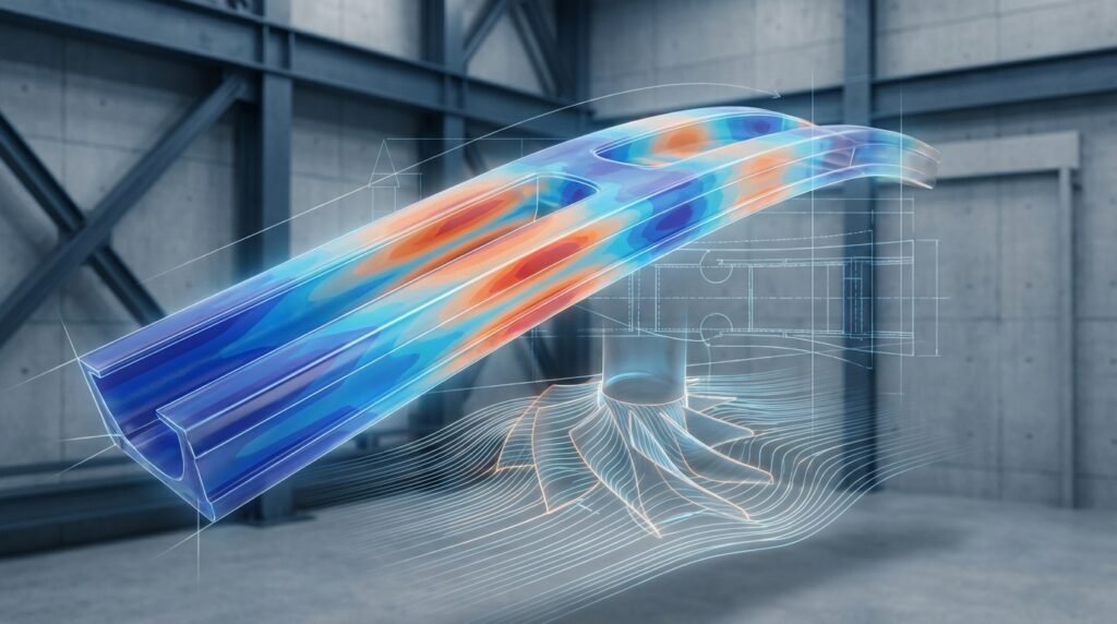
Illustrative image depicting stress distribution and potential fatigue hot-spots near a weld.
What is Fatigue in Welded Structures?
Fatigue is the progressive and localized structural damage that occurs when a material is subjected to cyclic or fluctuating stresses below its yield strength. In welded structures, this phenomenon is particularly critical for several reasons:
- Stress Concentrations: Welds, by their very nature, introduce geometric discontinuities (e.g., weld toes, roots, weld metal imperfections) that act as stress concentrators, amplifying local stresses.
- Material Alterations: The welding process involves heating and cooling cycles that can alter the microstructure and mechanical properties of both the base metal and the weld metal, creating heat-affected zones (HAZs) with reduced fatigue strength.
- Residual Stresses: The non-uniform heating and cooling during welding induce significant residual stresses. These stresses, if tensile, can accelerate fatigue crack initiation and propagation.
- Defects: Weld defects like porosity, lack of fusion, or undercut can act as pre-existing cracks or severe stress raisers.
Why is it so Important?
Fatigue failure is often sudden and catastrophic, occurring without obvious warning signs. For industries like oil & gas (offshore platforms, pipelines), aerospace (aircraft frames, engine components), and heavy machinery, a fatigue-induced failure can lead to immense economic loss, environmental damage, and, most critically, loss of life. Proactive fatigue analysis is thus a cornerstone of structural integrity management.
Key Factors Influencing Weld Fatigue
To perform accurate fatigue analysis, engineers must consider a multitude of interacting factors:
- Loading Conditions: The type of loading (tension, compression, bending, torsion), its magnitude, frequency, and load ratio (R-ratio = min stress / max stress) are all crucial. Variable amplitude loading requires advanced damage accumulation theories (e.g., Miner’s Rule).
- Material Properties: Beyond static strength, cyclic stress-strain behavior, fatigue limit (endurance limit), and crack propagation rates are essential. Different steels, aluminum alloys, or exotic materials will exhibit vastly different fatigue performances.
- Weld Geometry and Quality: The profile of the weld bead (e.g., angle at the weld toe), root penetration, and any imperfections significantly affect stress concentration. Good weld quality is paramount.
- Residual Stresses: As mentioned, tensile residual stresses are detrimental, while compressive residual stresses (sometimes induced intentionally) can improve fatigue life.
- Environmental Factors: Corrosion fatigue, fretting fatigue, and high-temperature fatigue are complex phenomena that can drastically reduce expected life, especially in harsh environments like marine or chemical processing.
Approaches to Fatigue Analysis for Welds
Several methodologies exist for fatigue assessment, each with its strengths and limitations. The choice often depends on the available data, required accuracy, and industry standards.
1. Stress-Life (S-N) Approach
This is the most common approach, based on empirical S-N curves derived from experimental tests. It relates an applied stress range (S) to the number of cycles to failure (N). Different S-N curves exist for different weld types, materials, and load ratios.
- Nominal Stress Approach: Compares the nominal stress in the structure (calculated far from the weld) with S-N curves specifically developed for welded joints, often categorized by weld class (e.g., AWS, DNV, Eurocode). This is simpler but can be conservative.
- Hot-Spot Stress (Structural Stress) Approach: Considers the stress at the weld toe or root, extrapolated from FEA results. This method is more accurate than nominal stress as it accounts for local geometry but excludes the sharp notch effect itself. It’s widely used in ship and offshore structures.
- Effective Notch Stress Approach: Introduces a small, fictitious notch radius (e.g., 0.05-1.0 mm, depending on the standard) at the weld toe/root in the FEA model. This allows for direct calculation of the stress concentration and application of plain material S-N curves (or specific notch-fatigue curves). It’s more computationally intensive but offers greater accuracy for complex geometries.
2. Strain-Life (ε-N) Approach
More suitable for low-cycle fatigue (high loads, few cycles) where plastic deformation occurs. It relates plastic strain amplitude to fatigue life. This method requires cyclic stress-strain properties of the material.
3. Fracture Mechanics Approach
Focuses on the propagation of existing cracks. It uses parameters like the stress intensity factor (K) to predict crack growth rate (Paris’s Law) and remaining life. Essential for Fitness-for-Service (FFS Level 3) assessments where defects are identified.
Practical Workflow: FEA for Weld Fatigue Assessment
Finite Element Analysis (FEA) is indispensable for detailed weld fatigue assessment. Here’s a typical workflow using commercial tools like Abaqus, ANSYS Mechanical, or MSC Patran/Nastran.
Step 1: Geometry & Meshing
- Model Simplification: Remove non-critical features. However, for weld fatigue, ensure the actual weld geometry (fillets, penetrations) is accurately represented.
- Weld Modeling: Decide on the fidelity. For nominal stress, a simplified weld may suffice. For hot-spot or effective notch stress, detailed weld bead profiles are crucial. CAD tools like CATIA or SolidWorks can be used for initial geometry, then imported into CAE pre-processors.
- Meshing Strategy: This is critical. Use a very fine mesh (e.g., 0.5-1.0 mm element size) at the weld toe and root, transitioning to a coarser mesh away from the stress concentration. Hexahedral elements are preferred where possible for accuracy, but tetrahedral elements might be necessary for complex geometries. Ensure good element quality (aspect ratio, Jacobian).
Step 2: Material Properties
- Elastic Properties: Young’s Modulus, Poisson’s Ratio.
- Cyclic Properties: For strain-life or advanced stress-life, you’ll need cyclic stress-strain curves, fatigue strength coefficient, fatigue ductility coefficient, etc. These are typically obtained from standardized material tests.
- S-N Curves: Select appropriate S-N curves based on the weld class, material, and environment from relevant codes (e.g., DNV RP-C203 for offshore, Eurocode 3).
Step 3: Loading & Boundary Conditions
- Apply Realistic Loads: Define static pre-loads and cyclic loads. This might involve pressure, force, displacement, or thermal loads. Consider load spectra (variable amplitude loading) if applicable.
- Boundary Conditions (BCs): Accurately constrain the model to represent the real-world support conditions without over-constraining. Ensure no rigid body motions.
- Load History: If using a time-domain fatigue analysis, apply the actual load history. For frequency-domain, define power spectral densities (PSDs).
Step 4: Fatigue Criteria Selection & Analysis
Most commercial FEA packages (Abaqus, ANSYS Mechanical Fatigue Module, MSC Nastran with nCode DesignLife) have integrated fatigue capabilities:
- Stress Classification: Extract appropriate stresses (nominal, hot-spot, effective notch stress) from your FEA results. For hot-spot, define paths to extrapolate stresses.
- Fatigue Algorithm: Choose your preferred algorithm (e.g., S-N based, ε-N based, critical plane for multiaxial fatigue).
- Damage Accumulation: For variable amplitude loading, apply a damage accumulation rule (e.g., Palmgren-Miner’s Rule).
- Post-Processing: Compute fatigue life, damage factors, or safety factors against fatigue failure.
Step 5: Post-processing & Results Interpretation
- Life Plots: Visualize predicted fatigue life contours on your model. Identify critical areas.
- Damage Plots: See where the highest damage accumulation occurs.
- Sensitivity Analysis: Evaluate how changes in input parameters (material properties, load amplitude) affect fatigue life. Python or MATLAB scripts can be invaluable for automating post-processing and parametric studies.
Verification & Sanity Checks in FEA for Weld Fatigue
Never blindly trust FEA results. Verification and validation are crucial, especially for fatigue analysis where small input changes can lead to large life variations.
- Mesh Sensitivity: Rerun the analysis with a finer and coarser mesh in critical regions to ensure results are convergent and not overly mesh-dependent.
- Boundary Condition Effects: Experiment with slight variations in BCs to understand their influence. Are your constraints realistic?
- Hand Calculations / Simplified Models: Perform simple checks where possible. Can you use beam theory or pressure vessel formulas to get an order-of-magnitude check on stresses?
- Compare to Standards/Literature: Do your results align with known fatigue strengths for similar weld types and materials from industry codes or research papers?
- Convergence Checks: For non-linear analyses (e.g., plasticity for residual stress), ensure solution convergence.
- Material Data Review: Double-check all material properties, especially cyclic data, against reliable sources.
- Load Path Verification: Does the stress distribution make physical sense? Are loads transmitting as expected through the structure?
Design Considerations for Fatigue-Resistant Welds
Preventing fatigue failure starts at the design stage.
1. Weld Geometry Optimization
- Smooth Transitions: Avoid sharp corners and sudden changes in cross-section. Larger fillet radii at weld toes significantly reduce stress concentration.
- Full Penetration Welds: For critical joints, full penetration welds are preferred over partial penetration to avoid internal defects and improve load transfer.
- Contour Grinding: Grinding the weld toe to create a smooth transition can drastically improve fatigue life.
2. Material Selection
- Choose materials with inherently good fatigue properties and appropriate weldability. High-strength steels often have higher static strength but can be more susceptible to fatigue if not designed or welded carefully.
3. Post-Weld Treatments
Several methods can improve the fatigue resistance of welds by modifying residual stresses or surface conditions:
- Grinding/Machining: Removes stress concentration points and surface defects.
- Shot Peening: Induces compressive residual stresses on the surface.
- Hammer Peening/Ultrasonic Impact Treatment (UIT): Similar to shot peening, creating compressive residual stresses and improving surface finish.
- TIG Dressing: Remelting the weld toe to smooth the profile and reduce stress concentration.
4. Quality Control & Inspection
- Strict adherence to welding procedures and rigorous non-destructive testing (NDT) such as ultrasonic testing (UT), magnetic particle inspection (MPI), or radiographic testing (RT) are essential to detect defects.
Common Mistakes and Troubleshooting in Weld Fatigue Analysis
Common Mistakes:
- Inadequate Meshing: Using a coarse mesh at critical weld locations, leading to inaccurate stress predictions.
- Ignoring Residual Stresses: Especially for as-welded conditions, tensile residual stresses can significantly reduce fatigue life.
- Incorrect Material Data: Using static properties for cyclic loading or selecting the wrong S-N curve for the specific weld class and environment.
- Oversimplified Loading: Not accounting for load history, mean stress effects, or multiaxial loading states.
- Ignoring Weld Defects: Assuming a perfect weld, when in reality, defects (even small ones) can be fatigue crack initiation sites.
- Using 2D Elements for Complex 3D Welds: 2D simplifications can miss critical 3D stress states.
Troubleshooting Tips:
- Review Mesh Quality: Always check element aspect ratio, skewness, and Jacobian at critical areas. Refine until stress convergence is achieved.
- Sensitivity Studies: Perform analyses by varying uncertain parameters (e.g., material fatigue strength, residual stress magnitude) to understand their impact.
- Consult Standards: Cross-reference your methodology and results with relevant industry standards (e.g., API, ASME, DNV) for specific design rules and recommended practices.
- Validate Against Test Data: If possible, compare predictions against experimental fatigue test data for similar joints.
- Expert Review: Have an experienced fatigue engineer review your model, assumptions, and results.
Challenges in Weld Fatigue Analysis
The complexity of weld fatigue analysis stems from several factors:
- Local Stress State: The highly localized and non-linear stress field around a weld due to geometry, material heterogeneity, and residual stresses.
- Multiaxial Loading: Welds often experience complex multiaxial stress states, requiring advanced fatigue criteria.
- Statistical Nature: Fatigue is inherently statistical. Scatter in material properties, weld quality, and loading makes deterministic predictions challenging.
- Size Effects: Fatigue behavior can be size-dependent, making direct extrapolation from small test specimens to large structures difficult.
Comparing Weld Fatigue Analysis Approaches
The table below summarizes the key characteristics of the discussed weld fatigue analysis approaches:
| Approach | Description | FEA Input / Complexity | Typical Application | Pros | Cons |
|---|---|---|---|---|---|
| Nominal Stress | Compares bulk stress to weld-specific S-N curves. | Low FEA detail, standard S-N curves. | Preliminary design, simple geometries, standard connections. | Simple, widely available S-N data. | Conservative, doesn’t capture local effects. |
| Hot-Spot Stress | Extrapolates stress at weld toe/root from FEA. | Medium FEA detail (fine mesh at welds), specific S-N curves. | Offshore, shipbuilding, pressure vessels. | Accounts for global geometry, less conservative than nominal. | Meshing rules are critical, still an approximation of stress. |
| Effective Notch Stress | Models weld toe/root with a small, fictitious radius; uses plain material S-N curves. | High FEA detail (very fine mesh at notch), plain S-N curves. | Complex geometries, high-precision applications (e.g., aerospace). | High accuracy, uses material S-N curves. | Computationally intensive, meshing rules can be complex. |
| Fracture Mechanics | Analyzes growth of existing cracks using stress intensity factors. | Requires initial crack geometry, material crack growth data. | Fitness-for-Service (FFS Level 3), defect assessment. | Predicts remaining life with defects, accounts for crack growth. | Requires known crack, complex analysis. |
For those looking to deepen their understanding or need specialized support, EngineeringDownloads.com offers online tutoring and consultancy services in advanced FEA and structural integrity, including customized Python and MATLAB scripts for post-processing and automation.
Further Reading
For detailed industry standards and recommended practices on fatigue design of welded structures, consult DNVGL-RP-C203: Fatigue Design of Offshore Steel Structures, available from the official DNV website.
Conclusion
Fatigue analysis in welded structures is a complex but critical discipline. By carefully applying appropriate methodologies, leveraging advanced FEA tools, and adhering to robust design principles, engineers can significantly enhance the structural integrity and reliability of their designs. Remember that thorough verification, sanity checks, and a deep understanding of material behavior are just as important as the advanced software tools themselves.