Understanding Mass Imbalance in Engineering Systems
Mass imbalance is a critical factor in the performance and longevity of almost any rotating or reciprocating machinery, from tiny biomedical centrifuges to massive power plant turbines. Simply put, it’s the uneven distribution of mass around a rotating axis. This seemingly minor issue can lead to significant problems, impacting structural integrity, operational efficiency, and even safety. For engineers working in fields like aerospace, oil & gas, or structural engineering, a solid grasp of mass imbalance is essential for robust design, accurate analysis, and effective troubleshooting.

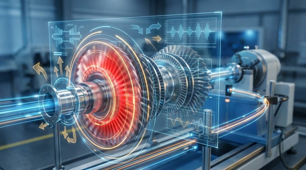
Image depicting a rotating shaft with an eccentric mass, illustrating mass imbalance. (Source: Wikimedia Commons)
What Exactly is Mass Imbalance?
Mass imbalance occurs when the center of gravity of a rotating object does not coincide with its axis of rotation. This offset creates a centrifugal force that rotates with the shaft, causing vibrations. We generally categorize imbalance into a few key types:
- Static Imbalance: Occurs when the principal axis of inertia is parallel to the axis of rotation but offset. You can detect this by allowing the rotor to roll to its heavy spot when placed on horizontal knife edges.
- Couple Imbalance: Happens when two equal and opposite static imbalances are present in different planes, creating a rocking motion. The center of gravity might lie on the axis of rotation, but the principal axis of inertia is skewed.
- Dynamic Imbalance: This is the most common and complex type, a combination of both static and couple imbalance. The principal axis of inertia is neither parallel nor intersecting with the axis of rotation. It requires balancing in at least two planes.
Why is Mass Imbalance a Significant Problem?
The consequences of unaddressed mass imbalance can range from annoying to catastrophic, impacting several aspects of an engineering system:
- Excessive Vibration: The most immediate and noticeable effect, leading to discomfort, noise, and potential operational issues.
- Increased Stress and Fatigue: Components experience cyclic loading, accelerating material fatigue and potentially leading to premature failure, a critical concern for structural integrity and FFS Level 3 assessments.
- Reduced Bearing Life: High vibration and load cycles on bearings drastically shorten their lifespan, increasing maintenance costs and downtime.
- Decreased Efficiency: Energy is wasted in vibration instead of productive work, leading to higher power consumption.
- Noise Pollution: Unwanted vibrations often generate significant noise, impacting working environments.
- Safety Hazards: In extreme cases, severe imbalance can cause structural failure or component ejection, posing significant risks.
Common Causes of Mass Imbalance
Understanding the root causes is the first step towards prevention and correction:
- Manufacturing Tolerances: Inherent variations in material density, dimensions, or geometry during manufacturing.
- Assembly Errors: Misalignment of components, eccentric mounting, or incorrect fit.
- Material Variations: Non-uniform casting, uneven material removal during machining, or internal voids (e.g., in composite structures or castings).
- Wear and Erosion: Over time, material loss due to friction, corrosion, or erosion (common in pumps, fans, and turbines in oil & gas).
- Deposits and Buildup: Accumulation of dirt, debris, or process material (e.g., scale in pipes, ice on wind turbine blades).
- Deformation: Permanent changes in shape due to thermal stress or excessive loading.
Detecting and Measuring Mass Imbalance
Engineers employ various methods to identify and quantify imbalance:
- Field Balancing: Performed on the machine’s operating site, using vibration sensors to measure amplitude and phase, then adding or removing mass to correct.
- Shop Balancing: Rotors are removed and placed on dedicated balancing machines that precisely measure imbalance and indicate correction points.
- Analytical Methods: For complex geometries or early design stages, CAD/CAE tools (like CATIA, SolidWorks, Abaqus, ANSYS Mechanical) can calculate the mass distribution and identify potential imbalance issues before physical prototyping.
Correcting Mass Imbalance: Balancing Techniques
Once detected, imbalance is corrected by adjusting the mass distribution:
- Adding Mass: Attaching balance weights (e.g., bolts, rings, epoxy) at specific locations.
- Removing Mass: Machining, drilling, grinding, or sanding material from the heavy spot.
Mass Imbalance in Design & Simulation Workflows
Modern engineering demands proactive approaches to mass imbalance. Integrating analysis early in the design phase significantly reduces costly redesigns and operational issues.
Practical Workflow for Simulating Imbalance Effects
Using CAE tools can predict how a component will behave under various imbalance conditions. Here’s a typical simulation workflow:
-
Model Creation and Geometry Preparation
Start with a high-fidelity CAD model (e.g., from CATIA, SolidWorks). Simplify unnecessary features while retaining critical geometry for mass distribution. For complex turbomachinery, this might involve integrating data from CFD tools like Fluent or OpenFOAM to capture fluid-structure interaction effects if a fluid film or dynamic fluid loading contributes to effective mass distribution.
-
Defining Material Properties and Imbalance
Assign accurate material properties. Mass imbalance can be simulated by:
- Directly adding a small, eccentric mass element.
- Modifying the density of a small region.
- Applying a rotating force or moment at the center of gravity, proportional to the expected imbalance magnitude and rotational speed. This is often done in rotordynamics analysis software like ADAMS, or general FEA platforms like Abaqus and ANSYS Mechanical through user-defined loads or specific rotordynamics modules.
-
Meshing Considerations
Generate a suitable mesh. For rotating components, consider mesh density, element type, and adaptivity, especially in regions of high stress or where imbalance is applied. Higher-order elements often provide better accuracy.
-
Setting Up Analysis Type
Typically, a transient dynamic analysis is performed to capture time-dependent vibrations. For rotordynamics, specific analysis types (e.g., Campbell diagram analysis) in tools like Abaqus, ANSYS, or MSC Nastran can identify critical speeds and instability regions. Python or MATLAB scripts can automate result extraction and visualization from these analyses.
-
Defining Boundary Conditions and Interactions
Accurately represent bearings, supports, and surrounding structures with appropriate boundary conditions (e.g., fixed, elastic supports, contact). Consider damping effects.
-
Running the Simulation and Post-Processing
Execute the analysis. Post-process results to visualize vibration amplitudes, stresses, strains, and fatigue life predictions. Python or MATLAB are excellent for automating data extraction, filtering, and generating custom plots or reports from large simulation datasets.
For engineers looking to push the boundaries of their simulations, EngineeringDownloads offers affordable HPC rental to run complex models, alongside online/live courses, internship-style training, and project/contract consultancy to deepen your expertise.
Verification & Sanity Checks for Imbalance Simulations
Ensuring the reliability of your simulation results is paramount:
- Mesh Quality: Always check element distortion, aspect ratio, and Jacobian values. Poor mesh quality can lead to inaccurate results or convergence issues. Perform mesh sensitivity studies.
- Boundary Condition Review: Double-check all constraints, loads, and connections. Ensure they accurately represent the physical system. Are your bearings modeled realistically?
- Convergence Criteria: Verify that the simulation has converged to a stable solution within acceptable tolerances, especially for transient analyses.
- Mode Shape & Natural Frequency Analysis: Before running dynamic simulations, perform a modal analysis to understand the component’s natural frequencies. If operating speed is close to a natural frequency, resonance will amplify imbalance effects dramatically.
- Simplified Analytical Models: Compare simulation results with hand calculations or simplified analytical models for basic cases (e.g., single mass on a simply supported beam) to catch major errors.
- Sensitivity Analysis: Vary the magnitude and location of the simulated imbalance to understand its impact on the system response.
- Validation: Whenever possible, compare simulation results with experimental data or field measurements from similar systems.
Industry Applications and Examples
- Oil & Gas: Turbomachinery (pumps, compressors, gas turbines), drilling equipment, and pipeline components. Imbalance leads to severe downtime and safety risks.
- Aerospace: Jet engine rotors, propeller blades, helicopter rotors. Critical for flight safety and performance.
- Biomechanics: Centrifuges, prosthetic joints, medical devices where precise rotation and minimal vibration are crucial.
- Structural Engineering: Large rotating antennas, wind turbine rotors, large cooling tower fans. Imbalance can induce significant structural loads.
Troubleshooting Mass Imbalance Issues
When unexpected vibrations arise, consider this troubleshooting checklist:
- Check for Visible Damage: Look for bent shafts, cracked components, or signs of wear.
- Inspect for Deposits/Debris: Clean rotating surfaces thoroughly.
- Verify Mounting: Ensure components are properly seated, tightened, and aligned.
- Bearing Condition: Worn or damaged bearings can mimic or exacerbate imbalance.
- Operating Speed Changes: Is the machine operating at or near a critical speed?
- Review Maintenance Records: Has any recent maintenance or repair introduced the imbalance?
Common Mistakes to Avoid in Mass Imbalance Management
- Ignoring Small Imbalances: Even seemingly minor imbalances can cause cumulative damage over time, especially in high-speed or long-life applications.
- Single-Plane Balancing for Dynamic Imbalance: Attempting to correct dynamic imbalance in only one plane is often ineffective and can even worsen the problem.
- Improper Weight Application: Incorrectly sized, placed, or secured balance weights can detach or be ineffective.
- Overlooking Environmental Factors: Temperature changes, aggressive fluids, or erosion can alter mass distribution.
- Neglecting Resonance: Operating near a critical speed will drastically amplify the effects of any remaining imbalance.
| Imbalance Type | Description | Detection Method | Correction Method | Typical Impact |
|---|---|---|---|---|
| Static Imbalance | Mass offset from rotation axis in one plane. | Rolls to heavy spot; single-plane balancer. | Add/remove weight in a single plane. | Vertical vibration, bearing wear. |
| Couple Imbalance | Equal/opposite static imbalances in different planes. | Two-plane balancer; rocking motion. | Add/remove weights in two planes. | Angular vibration, bearing wear. |
| Dynamic Imbalance | Combination of static & couple imbalance. | Two-plane dynamic balancer; vibration analysis. | Add/remove weights in two planes. | Complex multi-directional vibration, fatigue. |
Further Reading
For more in-depth knowledge on rotor balancing and international standards, consult resources from organizations specializing in machinery diagnostics and vibration analysis, such as academic papers on rotordynamics or industry standards like ISO 1940-1. You can find useful information on sites discussing these standards, for example, from companies that manufacture balancing equipment: Understanding Balancing Standards.
Conclusion
Mass imbalance is an intrinsic challenge in engineering that demands careful attention throughout the design, manufacturing, and operational phases. By understanding its causes, effects, and employing advanced simulation tools alongside practical detection and correction techniques, engineers can ensure the reliability, efficiency, and safety of their critical systems. Proactive management of mass imbalance is not just about reducing vibration; it’s about extending asset life and upholding structural integrity in high-stakes environments.