Mass imbalance is one of those fundamental engineering challenges that, if ignored, can lead to catastrophic failures, costly downtime, and significant safety risks. Whether you’re designing a high-speed turbine, analyzing an aerospace component, or maintaining heavy industrial machinery in the Oil & Gas sector, understanding and mitigating mass imbalance is absolutely critical.
At its core, mass imbalance refers to an uneven distribution of mass in a rotating body relative to its axis of rotation. This seemingly simple concept is responsible for generating unwanted centrifugal forces that can induce severe vibrations, accelerate wear, and ultimately compromise the structural integrity of your system. As engineers, our goal isn’t just to fix the problem when it arises, but to predict, prevent, and design systems that inherently minimize these risks.

Image Credit: Wikimedia Commons, user: Nenad Stojkovic
Understanding the Fundamentals of Mass Imbalance
Before diving into advanced analysis, let’s solidify the foundational concepts. Mass imbalance isn’t a singular phenomenon; it manifests in different forms, each with unique characteristics and corrective measures.
Defining Static vs. Dynamic Imbalance
- Static Imbalance: This occurs when the center of gravity of a rotating body is not aligned with the axis of rotation. Even when stationary, a statically unbalanced rotor will settle with its heavy spot at the bottom. Think of a bicycle wheel with a weight attached to one side – it will always rotate to bring that weight to the lowest point. Static imbalance can be corrected by adding a single weight in a single plane.
- Couple Imbalance: This is a special case of dynamic imbalance where two equal and opposite unbalanced masses are present in different planes along the shaft. While the center of gravity might lie on the axis of rotation (appearing statically balanced), the opposing forces create a “couple” that causes a wobbling motion during rotation.
- Dynamic Imbalance: The most common and complex type. Dynamic imbalance combines both static and couple imbalance. Here, the principal inertia axis of the rotating body is neither coincident with nor parallel to the axis of rotation. This means the heavy spot is not in a single plane, requiring corrective weights in at least two different planes to achieve balance. This is particularly prevalent in long rotors or components with varying cross-sections.
Common Causes of Mass Imbalance
Mass imbalance rarely happens without a reason. Identifying the root cause is paramount for effective prevention and correction.
- Manufacturing Tolerances: No manufacturing process is perfect. Slight variations in material distribution, machining errors, or assembly inaccuracies are inherent.
- Material Defects: Porosity in castings, inclusions in forgings, or inconsistencies in composite layups can lead to localized mass variations.
- Wear and Tear: Erosion, corrosion, or material buildup (e.g., scale in pipes, dirt on fan blades) can alter the mass distribution over time.
- Assembly Errors: Misalignment of components, eccentric mounting, or uneven tightening of fasteners can introduce imbalance.
- Deformation: Thermal distortions, plastic deformation under load, or creep can permanently change the geometry and mass distribution.
- Repair & Modification: Imperfect repairs or field modifications that aren’t properly balanced can introduce new imbalance.
Consequences of Uncorrected Imbalance
The impact of mass imbalance extends far beyond simple vibration. Its effects can ripple through an entire system:
- Excessive Vibration: The most obvious symptom, leading to discomfort, noise, and operational issues.
- Reduced Bearing Life: Imbalance forces add to the static loads on bearings, causing premature fatigue and failure.
- Increased Component Wear: Gears, seals, couplings, and other components experience accelerated wear due to dynamic loads.
- Structural Fatigue: Repeated stress cycles from imbalance forces can lead to fatigue cracking in shafts, casings, and supporting structures. This is a critical concern in Structural Integrity and FFS (Fitness-for-Service) Level 3 assessments.
- Energy Loss: Vibrating machinery consumes more energy, leading to reduced efficiency and higher operating costs.
- Operational Failure: In severe cases, high vibration levels can lead to catastrophic failure of the rotating component or its surrounding structure.
- Safety Hazards: Component ejection or structural collapse poses significant risks to personnel.
Identifying and Quantifying Mass Imbalance
Effective management begins with accurate identification and measurement.
Symptoms of Imbalance
- Distinct vibration at the rotational frequency (1x RPM).
- High bearing temperatures.
- Audible knocking or rattling sounds.
- Loosening of fasteners.
- Cracking in welds or structural components.
- Excessive power consumption.
Measurement Techniques
- Balancing Machines: The gold standard for measuring and correcting imbalance. These machines can be “hard-bearing” (for precise measurements) or “soft-bearing” (for larger rotors), and they determine the magnitude and angular location of imbalance in one or two planes.
- Field Balancing: For installed machinery, vibration analysis equipment (accelerometers, velocity sensors) is used to measure vibration at various points. Trial weights are added, and the change in vibration is used to calculate the required corrective weights. This often involves iterative steps and specialized software.
- Modal Analysis: For complex structures, modal analysis can help identify resonant frequencies that might be excited by imbalance forces. Tools like ANSYS Mechanical or Abaqus are invaluable here.
Mass Imbalance in Diverse Engineering Contexts
The impact of mass imbalance is widespread across industries.
Rotating Machinery (Oil & Gas, Power Generation)
Turbines, compressors, pumps, motors, and fans are prime candidates for imbalance issues. In Oil & Gas, downhole drilling equipment and pipeline pumps operate in challenging environments where wear and material buildup can rapidly induce imbalance. Regular balancing is a key part of preventive maintenance.
Aerospace Engineering
Aircraft engines, propellers, helicopter rotors, and turbo-pump assemblies in rocket propulsion systems demand exceptionally tight balance tolerances. Even slight imbalance can lead to fatigue in critical components, affecting safety and performance. Advanced FEA tools are often used during design to predict imbalance effects.
Biomechanics
While not ‘rotating machinery’ in the traditional sense, understanding mass distribution is crucial for prosthetics and medical devices. An unevenly weighted implant or prosthetic limb can alter gait, increase joint stress, and lead to discomfort or failure. This often involves detailed CAD modeling and biomechanical simulation.
Structural Engineering & Structural Integrity (FFS Level 3)
While structures themselves don’t rotate, they are often subjected to dynamic loads from rotating machinery. Imbalance forces can excite structural resonances, leading to excessive vibration and fatigue damage in supporting structures, foundations, and adjacent components. FFS Level 3 assessments may involve detailed finite element analysis to evaluate crack growth under such dynamic loading scenarios, requiring accurate modeling of imbalance forces.
Simulation and Analysis of Mass Imbalance
Modern engineering relies heavily on simulation to predict, understand, and mitigate the effects of mass imbalance before physical prototypes are built or failures occur.
CAD-CAE Workflow for Imbalance Analysis
- Concept & CAD Modeling: Start with accurate 3D models of rotating components in CAD software like CATIA, SolidWorks, or Inventor. Ensure detailed representation of material properties and potential areas of mass variation.
- Mass Property Calculation: Most CAD software can calculate mass, center of gravity, and moments of inertia. This data forms the baseline for identifying potential static imbalance.
- FEA/MBD Integration: Export the CAD model to CAE software.
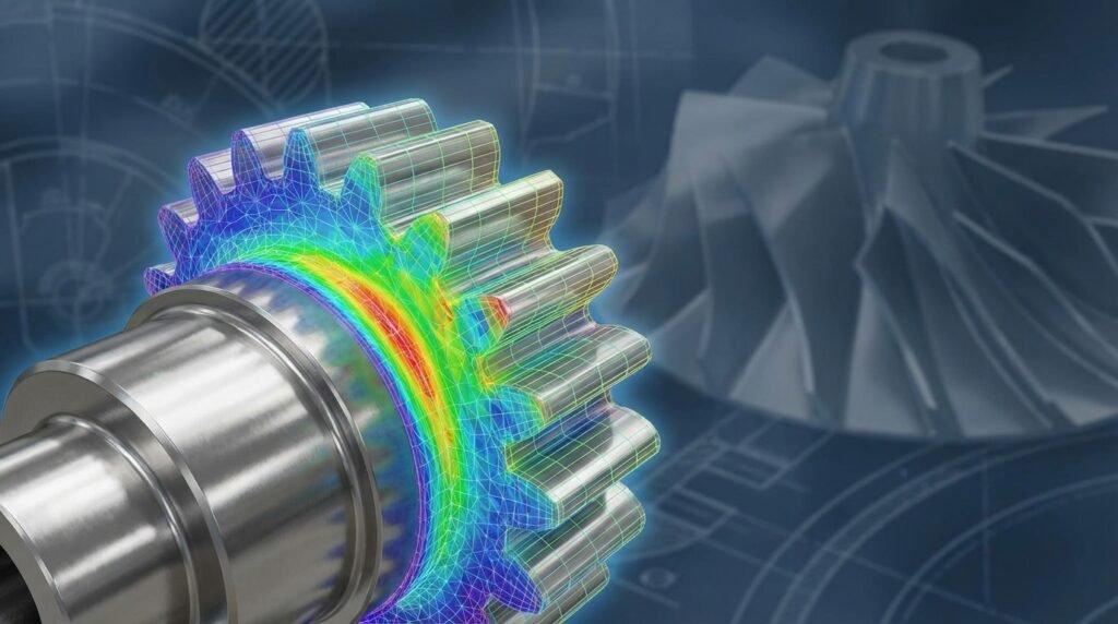
- Finite Element Analysis (FEA): For predicting stress and deformation under imbalance loads. Tools like ANSYS Mechanical, Abaqus, or MSC Nastran are used for modal analysis, harmonic response, and transient dynamic simulations.
- Multi-Body Dynamics (MBD): For complex assemblies with multiple rotating and interacting parts (e.g., gearboxes, entire engines). Software like ADAMS (MSC Software) is excellent for this, allowing the direct input of imbalance definitions and simulation of resulting forces and accelerations.
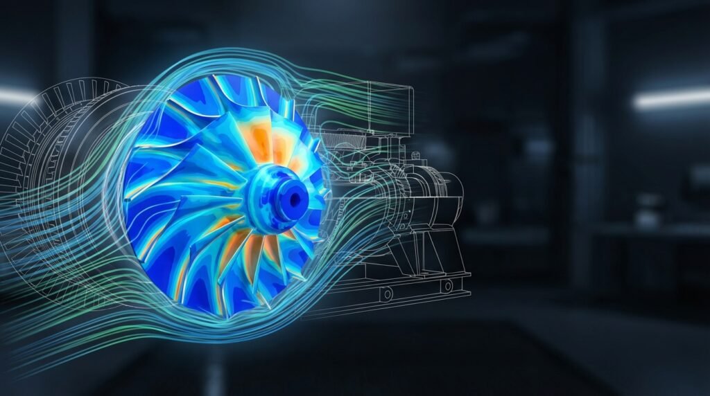
- CFD (if applicable): In some cases, fluid-structure interaction (FSI) might contribute to or be affected by imbalance. For instance, fluid flow through a pump impeller might cause cavitation or uneven pressure distributions that exacerbate an existing imbalance or even induce a ‘fluidic imbalance.’ Tools like ANSYS Fluent/CFX or OpenFOAM can be integrated with structural solvers for such complex scenarios.
- Material Definition: Accurately define material properties (density, Young’s modulus, Poisson’s ratio, damping) as these directly influence vibrational response.
Practical Workflow for Simulating Imbalance Effects
Let’s outline a step-by-step approach for simulating a dynamically unbalanced rotor using FEA/MBD tools.
Step 1: System Definition & Component Isolation
- Clearly define the rotating assembly, bearings, and supporting structure.
- Isolate the rotating components for detailed analysis.
- Understand the operational RPM range.
Step 2: Mass Property Definition & Imbalance Input
- In your CAE software (e.g., ANSYS Mechanical, Abaqus, ADAMS), ensure correct material densities are assigned.
- Representing Imbalance:
- Direct Mass Offset: Define a small mass offset (eccentricity) for the center of gravity of the rotating part. For instance, a 1g mass at a 100mm radius will generate a certain imbalance force.
- Unbalance Mass: Directly specify an unbalance mass and its angular position in a specific plane. Many MBD software packages allow you to define ‘unbalance elements.’
- Imposed Force/Moment: Apply a rotating centrifugal force (F = m * e * ω²) and/or moment, where ‘m’ is the unbalance mass, ‘e’ is its eccentricity, and ‘ω’ is the angular velocity.
Step 3: Boundary Conditions & Loading
- Bearings: Model bearings accurately using either rigid connections, spring-damper elements, or specialized bearing elements. Ensure appropriate stiffness and damping.
- Supports: Fix non-rotating components (casings, foundations) where appropriate.
- Rotational Speed: Apply the operating angular velocity. For harmonic response, sweep through a range of frequencies; for transient, define the time-dependent rotation.
Step 4: Meshing Considerations
- For dynamic analysis, mesh quality is paramount. Use appropriate element types (e.g., solids for bulky parts, shells for thin-walled structures, beams for shafts).
- Refine the mesh in areas of high stress concentration or where accurate vibration modes are critical (e.g., near bearings, fillets).
- Ensure consistent element sizing, especially if performing modal analysis to capture higher modes.
Step 5: Solver Settings & Analysis Type
- Modal Analysis: First, perform a modal analysis to identify natural frequencies and mode shapes. This helps to determine if any operational speeds coincide with resonances.
- Harmonic Response Analysis: If you are interested in the steady-state response to a rotating imbalance force at various frequencies, use harmonic analysis. This provides amplitude and phase of vibration.
- Transient Dynamic Analysis: For time-dependent phenomena, non-linear effects, or start-up/shut-down scenarios, transient analysis is required. This captures the full time history of displacements, velocities, accelerations, and stresses.
Step 6: Post-processing and Interpretation
- Vibration Amplitudes: Plot displacements, velocities, and accelerations at key locations (e.g., bearing housings).
- Stress & Strain: Evaluate stress levels in critical components to assess fatigue life.
- Bearing Forces: Analyze forces transmitted through bearings to ensure they are within design limits.
- Mode Shapes: Visualize mode shapes to understand how the structure vibrates.
- Campbell Diagrams: Plot natural frequencies against rotational speed to identify potential resonances.
Python & MATLAB Automation for Imbalance Analysis
For parametric studies, optimization, or processing large datasets, Python and MATLAB are indispensable.
- Python: Libraries like NumPy and SciPy are excellent for numerical computations, data manipulation, and scripting FEA software APIs (e.g., Abaqus Python scripting, ANSYS ACT). You can automate model creation, imbalance definition, solver execution, and post-processing tasks.
- MATLAB: Widely used for control system design, signal processing (e.g., filtering vibration data), and numerical analysis. It can also interface with CAE tools or be used for pre- and post-processing.
For engineers looking to streamline their analysis, EngineeringDownloads.com offers downloadable Python scripts and MATLAB templates specifically designed for common rotating machinery imbalance calculations and data processing. These resources can significantly accelerate your workflow and enhance accuracy.
Correction and Mitigation Strategies
Once imbalance is identified, the next step is correction.
Balancing Techniques
- Single-Plane Balancing: Applicable for ‘disc-like’ rotors where imbalance essentially lies in one plane. A single weight is added or removed at a specific angular position.
- Two-Plane Balancing: Necessary for ‘long’ rotors where dynamic imbalance is present. Weights are added or removed in two different planes along the rotor’s length. This is typically done on a balancing machine or through field balancing.
- On-Site Balancing: Performed directly on the installed machinery, often required for large, critical assets that cannot be easily removed.
Design Considerations for Prevention
The best correction is prevention. Incorporating imbalance considerations during the design phase is crucial.
- Symmetry: Design components with rotational symmetry whenever possible to ensure uniform mass distribution.
- Tolerances: Specify appropriate manufacturing tolerances for critical dimensions that affect mass distribution.
- Material Selection: Choose materials with consistent density and properties.
- Assembly Methods: Design for robust and repeatable assembly processes that minimize eccentricity.
- Balancing Features: Incorporate features (e.g., balancing rings, bolt holes) into the design to facilitate future balancing operations.
Verification & Sanity Checks in Simulation
No simulation is complete without rigorous verification. Trusting results blindly can lead to costly errors.
| Check Type | Description | Key Questions |
|---|---|---|
| Mesh Sensitivity | Varying mesh density to ensure results converge and are independent of element size. | Do peak vibrations or stresses change significantly with finer meshes? Are critical areas sufficiently refined? |
| Convergence Criteria | Ensuring the numerical solver has reached a stable solution, especially in transient or non-linear analyses. | Are solver iterations converging? Are energy balances satisfied? |
| Boundary Conditions (BCs) | Verify that constraints and loads accurately represent the physical system. | Are bearings modeled correctly (stiffness, damping)? Are fixed supports truly rigid? Is the rotational speed correctly applied? |
| Validation | Comparing simulation results against analytical solutions, hand calculations, or experimental data. | Does the simulated natural frequency match theoretical predictions or past test data? Do vibration amplitudes align with field measurements (if available)? |
| Energy Checks | For transient analysis, monitor kinetic and internal energy to ensure stability and accuracy. | Is the total energy conserved (or dissipated correctly with damping)? |
| Sensitivity Analysis | Investigating how uncertainties in material properties, geometry, or imbalance magnitude affect the results. | How sensitive are peak vibrations to a 10% change in eccentricity or material density? |
Common Mistakes & Troubleshooting Mass Imbalance
Even experienced engineers can overlook critical aspects. Here are common pitfalls and how to avoid them.
Common Mistakes
- Ignoring Manufacturing & Assembly Tolerances: Assuming perfect parts and assembly can lead to design-stage oversight. Always consider worst-case tolerance stack-ups.
- Inaccurate Material Properties: Using generic material data when specific properties (e.g., actual density of a casting) are critical.
- Poor Meshing: Using coarse meshes in critical regions, leading to inaccurate stress and vibration predictions.
- Incorrect Bearing Stiffness: Over-simplifying bearing models can drastically alter the predicted dynamic response.
- Overlooking Thermal Effects: Temperature gradients can induce significant thermal distortion and secondary imbalance.
- Misinterpreting Vibration Data: Confusing imbalance-induced vibration (1x RPM) with other sources like misalignment (2x RPM) or bearing defects (higher frequencies).
- Ignoring System Interaction: Analyzing a single component in isolation without considering its interaction with the rest of the system (e.g., support structure flexibility).
Troubleshooting Tips
- Validate Your Model: Always start with a simplified model with analytical solutions to build confidence in your approach.
- Start Simple: Begin with static imbalance, then progress to dynamic.
- Check Units Consistently: A common source of error in any simulation.
- Review Post-processing Animations: Visually inspect deformation and vibration patterns to catch logical errors.
- Consult Standards: Refer to ISO standards (e.g., ISO 21940-11:2016 for balancing criteria) for guidance on acceptable balance grades.
- Data Logging & Trending: For real systems, track vibration levels over time. A sudden increase often points to a new or worsening imbalance.
Tips for Robust Imbalance Management
- Integrated Design & Analysis: Incorporate imbalance analysis early in the design phase using CAD-CAE workflows to predict and mitigate issues.
- Quality Control in Manufacturing: Implement strict QC measures to minimize manufacturing errors and material defects.
- Precision Assembly: Ensure accurate assembly procedures to prevent installation-induced imbalance.
- Condition Monitoring: Implement continuous vibration monitoring systems for critical machinery to detect imbalance proactively.
- Regular Preventive Maintenance: Schedule routine balancing checks and corrective actions based on operational hours or condition trends.
- Operator Training: Ensure personnel understand the signs and implications of imbalance.
By adopting a holistic approach, from initial design through to predictive maintenance, engineers can significantly reduce the risks and costs associated with mass imbalance. For advanced support, including custom Python/MATLAB scripts for your specific imbalance analysis challenges or expert guidance on FFS assessments involving dynamic loads, consider our online consultancy services at EngineeringDownloads.com.
Further Reading
For more detailed information on balancing standards, refer to the ISO 21940-11:2016 Mechanical vibration — Rotor balancing — Part 11: Procedures and tolerances for rotors with rigid behaviour.
Frequently Asked Questions (FAQ) about Mass Imbalance
What is mass imbalance in simple terms?
Mass imbalance means that the weight of a rotating object isn’t evenly distributed around its central axis. Imagine a car tire that has a ‘heavy spot’ – when it spins, that heavy spot wants to fly outwards, causing vibrations and wobbling.
Why is mass imbalance a problem for engineers?
Uncontrolled mass imbalance generates significant centrifugal forces that cause excessive vibration, noise, and accelerated wear on bearings and other components. This can lead to structural fatigue, reduced machine efficiency, and potentially catastrophic failures, impacting safety and operational costs.
What’s the difference between static and dynamic imbalance?
Static imbalance occurs when the center of gravity of a rotor is offset from its axis of rotation, causing a heavy spot that will always settle downwards. Dynamic imbalance, which is more complex, involves mass distribution unevenness along the rotor’s length, creating both a heavy spot and a wobbling motion (a ‘couple’) during rotation, requiring correction in multiple planes.
How can simulation tools help analyze mass imbalance?
FEA (Finite Element Analysis) and MBD (Multi-Body Dynamics) software like ANSYS Mechanical, Abaqus, or ADAMS allow engineers to model rotating components and their support structures. By simulating an artificial imbalance, they can predict vibration amplitudes, stress levels, bearing forces, and identify critical speeds (resonances) before any physical testing or manufacturing, leading to safer and more efficient designs.
How is mass imbalance typically corrected?
Mass imbalance is primarily corrected through a process called ‘balancing.’ This involves adding or removing small amounts of mass (e.g., weights, material removal by grinding) at specific angular positions and planes on the rotor to redistribute the weight evenly around the axis of rotation, thereby neutralizing the imbalance forces. This is done using specialized balancing machines or field balancing techniques.
What are the key considerations for mass imbalance in aerospace design?
In aerospace, mass imbalance is critical for engine components, propellers, and helicopter rotors. Engineers must consider stringent tolerances, lightweighting, and high-speed operation. Even minute imbalances can lead to significant vibratory loads, requiring advanced materials, precise manufacturing, and rigorous testing and simulation (often using FEA/MBD) to ensure structural integrity and flight safety.
Relevant EngineeringDownloads.com Internal Links:
- Vibration Analysis & Diagnostics
- Fatigue Analysis & Life Prediction
- Finite Element Analysis (FEA) Best Practices
- Multi-Body Dynamics (MBD) Applications
- Python for Engineering Automation