

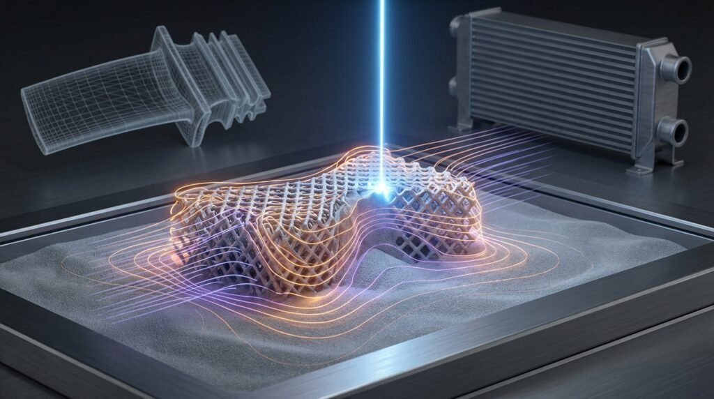
Laser Powder Bed Fusion (LPBF) has revolutionized how we design and manufacture complex components, from critical aerospace parts to custom medical implants. But as with any advanced manufacturing process, optimizing LPBF and predicting its outcomes—like part distortion, residual stress, and microstructure—can be a significant challenge. This is where LPBF simulation comes in, offering a powerful virtual laboratory to understand, predict, and fine-tune your additive manufacturing operations before committing to expensive physical builds.

Image: An industrial LPBF machine meticulously building a metal part layer by layer.
Introduction to LPBF Simulation
LPBF simulation leverages the power of computational mechanics, primarily Finite Element Analysis (FEA) and sometimes Computational Fluid Dynamics (CFD) for melt pool dynamics, to model the intricate physics involved in the additive manufacturing process. Imagine being able to predict exactly how a part will deform, where residual stresses will concentrate, or how a change in laser power might affect its final integrity—all from your desk. That’s the promise of LPBF simulation.
Why Simulate LPBF? The Engineering Edge
The benefits of integrating simulation into your LPBF workflow are compelling:
- Reduced Cost and Time: Minimize trial-and-error physical prototypes.
- Enhanced Quality: Predict and mitigate defects like distortion, cracking, and porosity.
- Optimized Process Parameters: Fine-tune laser power, scan speed, and hatch spacing virtually.
- Performance Prediction: Understand mechanical properties and structural integrity before manufacturing.
- Complex Design Exploration: Validate designs for intricate geometries unachievable with traditional methods.
Understanding LPBF Process Physics
LPBF is a multiphysics process, meaning several interacting physical phenomena occur simultaneously. For effective simulation, we need to understand the core physics at play.
Thermal Aspects
The laser’s interaction with the powder bed generates intense localized heating, melting the metal powder. This thermal cycle is rapid and highly transient, leading to significant temperature gradients. Key considerations include:
- Melt Pool Dynamics: The behavior of the molten metal, including convection and surface tension.
- Heat Conduction: How heat dissipates into the surrounding powder and previously solidified layers.
- Phase Transformations: Melting and solidification, which are critical for microstructure formation.
Mechanical Aspects: Residual Stress and Distortion
As the molten metal solidifies and cools, it contracts. However, this contraction is constrained by the cooler, already solidified material, leading to:
- Residual Stresses: Internal stresses ‘locked in’ the material after cooling, which can affect fatigue life and structural integrity.
- Distortion: Macroscopic deformation or warpage of the part due to uneven residual stress distribution. Predicting distortion is often a primary goal of part-scale LPBF simulations.
Microstructure Evolution (Briefly)
The rapid heating and cooling cycles inherent to LPBF significantly influence the material’s microstructure, which in turn dictates its final mechanical properties. While directly simulating microstructure at the part scale is computationally intensive, understanding its drivers helps interpret macroscopic simulation results.
Key Simulation Approaches for LPBF
Simulating LPBF can be tackled at different scales, each offering unique insights.
Process-Scale Simulation (Melt Pool Level)
This approach focuses on the immediate interaction of the laser with the powder bed. It’s highly detailed but computationally demanding, typically covering only small volumes.
- Focus: Melt pool geometry, cooling rates, porosity formation mechanisms, heat affected zone.
- Methods: Often uses CFD-FEA coupled approaches. Techniques like element activation (or ‘birth and death’ elements) in FEA tools like Abaqus or ANSYS are used to simulate material deposition layer-by-layer.
- Insight: Crucial for optimizing fundamental process parameters and understanding defect formation.
Part-Scale Simulation (Whole Part Level)
For predicting distortion and residual stress of the entire printed component, part-scale simulation is the go-to. It simplifies the melt pool physics to be computationally feasible for larger geometries.
- Focus: Global distortion, residual stress distribution, support structure optimization.
- Methods: Commonly uses thermo-mechanical FEA.
- Layer-by-layer (LBL) approach: Simulates the thermal and mechanical response for each deposited layer, which is accurate but very expensive.
- Inherent strain approach: A computationally efficient method where experimentally or process-scale derived ‘inherent strains’ (representing the net effect of thermal expansion/contraction) are applied to elements. This is excellent for large parts.
- Insight: Essential for manufacturing engineers to validate part design and optimize build orientation and support structures.
Microstructure Simulation (Specialized)
While less common in routine engineering workflows, some advanced simulations focus on predicting grain growth, phase distribution, and defect formation at the microstructural level. These often use methods like Cellular Automata (CA) or Phase-Field models, typically for research or highly specialized applications.
Practical Workflow for LPBF Simulation
A structured approach is key to successful LPBF simulation, bridging the gap between CAD and valuable engineering insights.
Step 1: Define Objectives & Scope
Before touching any software, clarify what you want to achieve. Are you aiming to:
- Minimize distortion for a specific geometry?
- Predict residual stress to prevent cracking?
- Optimize support structure design?
- Understand the impact of a specific process parameter?
Your objective will guide your choice of simulation approach (process vs. part scale) and required fidelity.
Step 2: Material Characterization
Accurate material properties are paramount. For LPBF simulation, you’ll need temperature-dependent properties:
- Thermal conductivity
- Specific heat
- Density
- Coefficient of thermal expansion
- Young’s modulus
- Yield strength
- Poisson’s ratio
For advanced simulations, consider latent heats of fusion and solidification, and even melt pool viscosity if dealing with CFD.
Step 3: Geometry & Meshing Considerations
Start with your CAD model. Simplify features that don’t significantly impact the physics you’re studying to reduce computational load. Meshing is critical:
- Element Type: Use solid elements (e.g., hexahedral or tetrahedral) for 3D parts.
- Adaptive Meshing: Some solvers offer adaptive meshing to refine elements in high-gradient regions (e.g., around the melt pool).
- Computational Cost vs. Accuracy: This is a constant trade-off. Fine meshes around critical areas and coarser elsewhere can be effective.
Mesh Refinement Strategies
For part-scale simulations, a coarser mesh throughout the bulk of the part is often used, with refinement near support structures or critical features where distortion is most impactful. For process-scale, extremely fine meshes are needed in the melt pool region.
Step 4: Setting Up the Simulation Model
This is where you translate the physical process into your chosen FEA software (e.g., Abaqus, ANSYS Mechanical).
Boundary Conditions & Loads
Accurate representation of boundary conditions is vital:
- Thermal Loads: Heat flux from the laser, convection to ambient air, radiation from the part and powder bed, conduction to the build plate.
- Mechanical Constraints: Fixities applied by the build plate and support structures. These are critical for resisting distortion.
Material Models (Temperature-Dependent)
Ensure your material models correctly capture the behavior of the alloy across its melting and solidification range. Non-linear material models (elastic-plastic) are often necessary to capture residual stresses accurately.
Step 5: Solver Selection & Execution
Choose an appropriate solver:
- Commercial FEA: Abaqus, ANSYS Mechanical, MSC Nastran, and Simufact Additive are powerful tools, often with dedicated additive manufacturing modules that simplify setup for LPBF.
- Custom Scripts: For specialized research or highly customized workflows, Python or MATLAB can be used to drive simulations, automate pre/post-processing, or implement novel material models.
Execution can be computationally intensive, especially for layer-by-layer approaches. High-performance computing (HPC) resources are often beneficial.
Step 6: Post-processing & Interpretation
After the simulation runs, interpret the results. Visualize key outputs:
- Deformation/Distortion: Compare against initial CAD.
- Residual Stress: Identify high-stress regions.
- Temperature Fields: Check thermal gradients.
Use these insights to iterate on your design, process parameters, or support strategies.
Tools of the Trade: Software for LPBF Simulation
The engineering software landscape offers various powerful options for tackling LPBF simulation challenges.
Commercial FEA Packages
These industry-standard tools provide robust frameworks for thermal and structural analysis, often with specialized modules for additive manufacturing:
- Abaqus: Known for its powerful non-linear capabilities and element activation/deactivation features, making it suitable for LBL simulation.
- ANSYS Mechanical: Offers a comprehensive suite including ANSYS Additive Prep and ANSYS Additive Print, which streamline the setup and analysis of LPBF processes, including inherent strain and detailed LBL simulations.
- MSC Nastran/Patran: Another powerful FEA solver, often used in conjunction with Patran for pre/post-processing, capable of complex thermo-mechanical analyses.
Specialized Additive Manufacturing Software
Some vendors offer tools specifically designed for AM simulation, often integrating various methods for efficiency:
- Simufact Additive: Focused entirely on AM process simulation, providing tools for distortion compensation, residual stress prediction, and build process optimization.
- Netfabb (Autodesk): Offers features for build preparation, support generation, and some simulation capabilities for thermal and mechanical behavior.
Open-Source Options
While less common for direct part-scale thermo-mechanical LPBF simulation, open-source tools can be valuable:
- OpenFOAM: Primarily a CFD toolbox, it can be adapted for highly detailed melt pool thermal/fluid dynamics simulations, though typically not for whole-part distortion.
- FEniCS Project: A powerful framework for solving PDEs with finite elements, which could be used to build custom LPBF solvers, but requires significant programming expertise.
Scripting & Automation
Don’t underestimate the power of scripting languages to enhance your simulation workflow:
- Python: Indispensable for automating pre-processing tasks (e.g., generating complex geometries, modifying input decks), running parametric studies, and post-processing results from tools like Abaqus (using its scripting API) or ANSYS.
- MATLAB: Useful for data analysis, developing custom material models, and scripting specific numerical routines, often integrated with commercial FEA via co-simulation or external calls.
Common Challenges and Pitfalls in LPBF Simulation
LPBF simulation is powerful, but not without its hurdles. Being aware of these can save you significant time and effort.
Material Data Availability
One of the biggest challenges is obtaining accurate, temperature-dependent material properties, especially for novel alloys or specific powder characteristics. Experimental characterization is often necessary, which can be costly and time-consuming.
Computational Cost
Detailed layer-by-layer simulations can take days or even weeks on powerful workstations, sometimes requiring HPC clusters. This can impact project timelines and budget. Strategies like inherent strain or sub-modeling help manage this.
Accurate Boundary Conditions
Defining realistic thermal and mechanical boundary conditions (e.g., heat transfer to the build plate, convection coefficients) can be tricky. Small inaccuracies can lead to significant deviations in results.
Complex Multiphysics Interactions
LPBF involves highly coupled thermal, mechanical, and sometimes metallurgical phenomena. Simplifying these interactions too much can compromise accuracy, while including all of them can lead to intractable computational models.
Verification & Sanity Checks for LPBF Simulations
Just like any FEA, LPBF simulations demand rigorous checks to ensure reliability and accuracy.
Mesh Sensitivity Analysis
Always perform a mesh sensitivity study. Vary your mesh density and observe if key output parameters (e.g., maximum distortion, peak stress) change significantly. A converged solution means further mesh refinement won’t drastically alter the results.
Convergence Criteria
Ensure your solver’s convergence criteria are met, especially for non-linear thermo-mechanical analyses. Failure to converge indicates numerical instability or an ill-posed problem, rendering results unreliable.
Validation Against Experimental Data
The ultimate test of any simulation is its ability to predict real-world behavior. Compare your simulation results for distortion, residual stress, or even part density against physical measurements from actual LPBF builds. Start with simple geometries for easier validation.
Sensitivity Studies (Process Parameters)
Run simulations with slight variations in critical process parameters (e.g., laser power, scan speed). This helps you understand the robustness of your process and quantify the impact of manufacturing tolerances on your final part.
Case Study Example: Predicting Distortion in an Aerospace Bracket
Consider an illustrative example: an aerospace company wants to print a complex titanium alloy bracket via LPBF. The challenge is predicting and mitigating distortion to ensure tight dimensional tolerances.
Simulation Approach: The team opted for a part-scale inherent strain analysis using ANSYS Additive Print. They characterized the Ti-6Al-4V alloy and obtained inherent strain data from simpler build plate coupons.
Workflow Highlights:
- Imported the bracket’s CAD geometry.
- Generated support structures within the software.
- Applied inherent strain tensors based on the chosen process parameters.
- Ran the simulation to predict total distortion and residual stress.
Results & Action: The simulation indicated a maximum displacement of 0.8 mm (illustrative value) at specific thin features. Based on this, the engineers adjusted the build orientation and redesigned support structures, iteratively running simulations until distortion was reduced to an acceptable 0.2 mm (illustrative value). This virtual optimization saved several expensive physical build iterations.
Actionable Tips for Successful LPBF Simulation
- Start Simple, Then Scale Up: Begin with small, representative geometries to establish your methodology and validate material models before tackling full-scale components.
- Leverage Inherent Strain: For part-scale distortion prediction, the inherent strain method offers an excellent balance of accuracy and computational efficiency. Invest time in properly characterizing these strains.
- Collaborate with Experimentalists: Close collaboration with those performing physical builds and characterization is invaluable. Simulation and experimental data should feed into each other for continuous improvement.
- Automate Repetitive Tasks: Use Python or MATLAB scripts to automate pre-processing, execute batch simulations, and extract key results. This dramatically speeds up design iterations and parametric studies.
- Consider Expert Guidance: If you’re encountering complex issues or need to accelerate your learning,EngineeringDownloads.com offers downloadable Python scripts for simulation automation, practical project templates, and expert online consultancy services to help you master advanced CAE techniques.
Comparison of LPBF Simulation Approaches
Here’s a quick overview of the typical applications and characteristics of different simulation fidelity levels:
| Approach | Fidelity Level | Primary Output | Computational Cost | Typical Tools |
|---|---|---|---|---|
| Process-Scale (Melt Pool) | High | Melt pool geometry, porosity, microstructure drivers | Very High | Abaqus, ANSYS Fluent/Mechanical, OpenFOAM (custom) |
| Part-Scale (LBL Thermo-Mechanical) | Medium-High | Distortion, residual stress (detailed) | High | Abaqus, ANSYS Mechanical, Simufact Additive |
| Part-Scale (Inherent Strain) | Medium | Distortion, residual stress (efficient) | Medium | ANSYS Additive Print, Abaqus (custom), Simufact Additive |
Frequently Asked Questions (FAQ)
-
What is the main goal of LPBF simulation?
The primary goal of LPBF simulation is to predict and mitigate common issues like part distortion, residual stresses, and defects, ultimately reducing trial-and-error builds, saving costs, and improving the quality and performance of additively manufactured components.
-
Which software is best for LPBF simulation?
There isn’t a single ‘best’ software; it depends on your specific needs. Leading commercial FEA packages like ANSYS (especially its Additive Suite) and Abaqus are widely used. Specialized tools like Simufact Additive offer focused workflows. For automation and custom analyses, Python and MATLAB are invaluable.
-
Is LPBF simulation computationally expensive?
Yes, especially detailed layer-by-layer thermo-mechanical simulations. These can require significant computing resources and time. However, more efficient methods like the inherent strain approach help manage computational cost for larger parts.
-
What kind of material data is needed for LPBF simulations?
You need temperature-dependent material properties including thermal conductivity, specific heat, density, coefficient of thermal expansion, Young’s modulus, yield strength, and Poisson’s ratio. Accurate material characterization is critical for reliable results.
-
How do I validate my LPBF simulation results?
Validation typically involves comparing simulation predictions (e.g., distortion, residual stress) against experimental measurements from physical builds. Starting with simple benchmark geometries for validation is a common and effective strategy.
Further Reading
For more detailed technical information on Additive Manufacturing simulation, explore official software documentation:


