

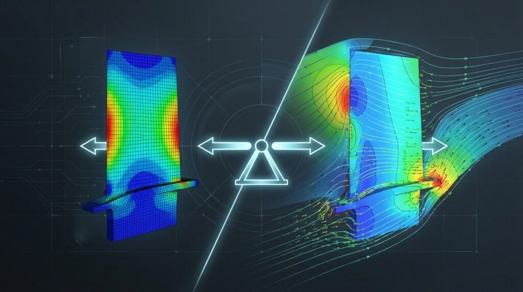
In the world of engineering simulation, whether you’re tackling complex structural integrity challenges with Finite Element Analysis (FEA) or analyzing fluid flow with Computational Fluid Dynamics (CFD), the concept of a force balance check is absolutely fundamental. It’s more than just a theoretical principle; it’s a critical diagnostic tool, a sanity check, and often the first line of defense against erroneous simulation results. Failing to properly check force balance can lead to incorrect designs, safety hazards, and significant project delays.

Illustration of forces acting on an object, a foundational concept for force balance.
What is a Force Balance Check?
At its core, a force balance check verifies that the sum of all external forces and moments acting on a system, or any part of it, is in equilibrium. This principle, derived directly from Newton’s Laws of Motion, dictates that for a system in static equilibrium, the net force and net moment must both be zero. In dynamic simulations, the net force equals the mass times acceleration (F=ma), and the net moment equals the mass moment of inertia times angular acceleration (M=Iα).
Why is Force Balance Critical in FEA and CFD?
For engineers using tools like Abaqus, ANSYS Mechanical, Fluent, or OpenFOAM, a robust force balance check serves multiple vital purposes:
- Ensuring Structural Integrity: In structural FEA, it confirms that applied loads are correctly resisted by reaction forces at supports. If they don’t balance, your structure is either moving (unintended rigid body motion) or the loads/constraints are improperly defined. This is crucial for FFS Level 3 assessments in oil & gas.
- Validating CFD Results: In CFD, comparing integrated pressure and viscous forces on a body to external forces (like gravity or thrust) ensures the simulation accurately captures the fluid-structure interaction. Imagine calculating lift and drag on an aircraft wing; if the integrated forces don’t match the expected aerodynamic loads, your results are suspect.
- Debugging Model Setup: Imbalances often pinpoint fundamental errors in boundary conditions, applied loads, contact definitions, or element formulations. It’s an invaluable diagnostic tool during the setup phase of any CAD-CAE workflow.
- Gaining Confidence: A successfully balanced system instills confidence in your model’s accuracy, allowing you to trust subsequent stress, strain, displacement, or flow field results for design decisions.
- Troubleshooting Convergence: In iterative solvers, large force imbalances can indicate poor convergence or numerical instability.
The Fundamental Principles: Newton’s Laws Applied
The entire concept hinges on Newton’s first and second laws of motion:
- First Law (Law of Inertia): An object at rest stays at rest and an object in motion stays in motion with the same speed and in the same direction unless acted upon by an unbalanced force. For static analysis, this means the sum of forces is zero.
- Second Law (F=ma): The acceleration of an object as produced by a net force is directly proportional to the magnitude of the net force, in the same direction as the net force, and inversely proportional to the mass of the object. For dynamic analysis, the net external force must equal the mass times acceleration.
In simulation, we typically examine the sum of external applied forces and external reaction forces (e.g., at fixed supports, contacts, or fluid-structure interfaces). For a well-posed static problem, these should sum to zero within an acceptable tolerance.
Practical Workflow for Force Balance Checks
Integrating force balance checks throughout your simulation workflow is key to robust analysis. Here’s a typical approach:
Pre-Analysis Considerations: Planning for Equilibrium
- Free-Body Diagrams (FBDs): Before touching any software, sketch FBDs for your entire system and critical sub-components. Identify all external loads, moments, and anticipated reaction forces. This is your mental roadmap for equilibrium.
- Load Path Identification: Understand how loads are transferred through your model. This helps predict where reactions should occur and anticipate areas needing careful boundary condition definition.
- Boundary Condition (BC) Planning: Carefully define supports, constraints, and applied loads. Consider if your BCs might introduce unintended rigid body motion or over-constrain the system. For instance, in structural mechanics, a pin support allows rotation but resists translation in all directions, while a roller allows translation in one direction.
- Simplified Hand Calculations: For simple cases (e.g., a beam under uniform load), perform quick hand calculations to estimate global reaction forces. This provides an initial benchmark for your simulation results.
During-Analysis Monitoring: Keeping an Eye on Stability
Most advanced solvers offer features to monitor force balance during the solution process:
- Solver Output Files: Check the
.dat,.msg, or.outfiles for information on residual forces, energy balance, and warnings. Abaqus’s.datfile, for example, often reports global equilibrium information at each increment. - Convergence Criteria: Pay attention to the convergence of forces and moments. If residuals don’t drop to an acceptable level (e.g., 10-6 for forces), it indicates an imbalance or convergence issue.
- Energy Balance: For non-linear or dynamic problems, monitoring internal energy, kinetic energy, and external work provides another layer of confidence. For example, in ADAMS or MSC Patran/Nastran, energy plots can reveal instabilities.
Post-Analysis Verification: The Final Check
This is where you systematically confirm equilibrium:
- Summing Reaction Forces: In structural FEA (e.g., Abaqus, ANSYS Mechanical), extract the total reaction forces (e.g.,
*RFin Abaqus) at all constrained degrees of freedom. Compare these sums against the total applied loads. For example, if you apply 1000 N in the Y-direction, the sum of reaction forces in the Y-direction should be -1000 N (or close to it). - Section Force/Moment Reporting: Many software packages allow you to cut sections through your model and integrate forces and moments over those sections. This is powerful for checking internal equilibrium within components.
- Integrated Forces in CFD: In CFD tools like Fluent or OpenFOAM, use surface integrals to calculate pressure and viscous forces on bodies (e.g., airfoil surfaces, pipe walls). Compare these to the forces expected from your boundary conditions or external forces like gravity.
- Global vs. Local Checks: Start with a global check for the entire assembly. If an imbalance exists, then perform local checks on sub-assemblies or individual components to isolate the problem area.
- Tolerance Check: No simulation will yield perfect zero. Define an acceptable tolerance (e.g., imbalances less than 1% of the total applied load). The magnitude of the imbalance relative to the applied loads is more important than its absolute value.
Common Scenarios & Applications
Structural Engineering (FEA)
- Supports and Constraints: Verify that the sum of reaction forces at all fixed supports perfectly balances the total applied external forces. This is paramount for bridge design, building structures, and machine components.
- Contact Problems: In models with contact (e.g., bolted joints, interference fits), ensure the contact forces are balanced. An imbalance might indicate poor contact convergence or numerical chatter, especially important for simulating engine components or orthopedic implants in biomechanics.
- Preloaded Structures: For preloaded bolts or cables, ensure that the internal forces generated by the preload are correctly balanced by reactions or other internal stresses.
Fluid Dynamics (CFD)
- Lift and Drag: Calculate the integrated pressure and viscous forces on an aerodynamic body (e.g., wing, car). The components of this force vector should correspond to the expected lift and drag. This is crucial for aerospace applications.
- Pressure Vessels: For a pressure vessel, the integrated pressure force on the internal walls must balance the reaction forces from the support structure and any externally applied forces. This is vital in oil & gas for pipelines and tanks.
- Turbomachinery: In rotating machinery (e.g., turbines, pumps), verify the balance of forces on rotor blades to ensure stable operation and predict bearing loads.
Biomechanics
- Joint Loads: When simulating human movement or prosthetic devices, force balance checks are used to ensure that the calculated joint reaction forces and muscle forces are in equilibrium with external loads and segment inertia. This is critical for evaluating implant designs or understanding injury mechanisms.
Tools & Software Implementation
Commercial FEA/CFD Software
- Abaqus: Use output requests like
RF(Reaction Force) andRM(Reaction Moment) to sum reactions. You can also define history outputs for total forces across sections. Python scripting (Abaqus Scripting Interface) can automate these checks. - ANSYS Mechanical: Post-processing tools allow direct summation of reaction forces at supports. You can also use commands to create sections and report integrated forces/moments. ANSYS ACT (Customization Toolkit) can be used for automation.
- Fluent/CFX: The ‘Reports’ menu provides options for ‘Forces’ and ‘Moments’ on surfaces (walls, inlets, outlets). You can integrate pressure and viscous forces to get total aerodynamic/hydrodynamic loads.
- MSC Nastran/Patran: Post-processing tools in Patran allow users to sum reaction forces. Nastran’s F06 file also contains detailed equilibrium checks.
Open-Source & Scripting
- OpenFOAM: Utilities like
forcesorforceCoeffscan be used to calculate and report forces and moments on specified patches (surfaces). Post-processing with ParaView also allows for surface integration. - Python & MATLAB: These are invaluable for automating post-processing and force balance checks, especially for large datasets or parametric studies. You can write scripts to extract nodal reaction forces or integrated surface forces from solver output files and perform the summation and comparison programmatically. This is particularly useful for complex FFS Level 3 assessments.
Verification & Sanity Checks for Robust Results
Force balance is one component of overall model verification. To ensure truly robust results, integrate these additional sanity checks:
Mesh Checks
- Element Quality: Poor element quality (e.g., highly distorted, inverted elements) can lead to inaccurate stiffness calculations and force imbalances. Use mesh diagnostics (aspect ratio, skewness, Jacobian ratio).
- Mesh Density: Ensure sufficient mesh density in areas of high-stress gradients or complex flow features. Coarse meshes can misrepresent loads and reactions.
- Non-matching Meshes: If using non-conforming meshes or sub-modeling, ensure interface connections (e.g., tie constraints, general contact) are properly defined to transfer forces accurately across boundaries.
Boundary Condition (BC) Checks
- Visualization: Always visualize applied loads and BCs to confirm they are on the correct surfaces/nodes and in the intended directions.
- Magnitude and Units: Double-check the magnitude and units of all loads and prescribed displacements/velocities. A common mistake is using incorrect unit systems.
- Rigid Body Motion: For static analyses, ensure your model is adequately constrained to prevent rigid body motion. If a model can translate or rotate freely, it will not converge, or it will yield infinite displacements and severe force imbalances.
Convergence Checks
- Solution Convergence: Monitor solver residuals. For non-linear problems, ensure both force and displacement iterations converge to within specified tolerances. Lack of convergence often directly correlates with poor force balance.
- Energy Convergence: In dynamic or implicit analyses, plot internal energy, kinetic energy, and external work. For a well-behaved simulation, energy should be conserved or properly dissipated.
Validation & Sensitivity Checks
- Analytical/Experimental Validation: Whenever possible, validate your simulation results (including force balance) against simplified analytical solutions or experimental data. This is the ultimate proof of fidelity.
- Sensitivity Analysis: Perform sensitivity studies on critical parameters like material properties, load magnitudes, and BC locations. Observe how force balance changes. This helps understand the robustness of your model.
Troubleshooting Imbalances
If your force balance check reveals significant discrepancies, here’s a structured approach to troubleshooting:
When grappling with complex engineering analyses, especially those demanding high computational resources for detailed force balance checks or extensive parameter studies, consider leveraging specialized services. EngineeringDownloads.com offers affordable HPC rental to run your models efficiently, alongside online courses and project consultancy to enhance your simulation capabilities.
Initial Diagnostic Steps
- Review Solver Output: Start by thoroughly examining the solver’s log or output file. Look for warnings about excessive element distortion, contact non-convergence, large displacements, or rigid body motion.
- Isolate the Problem: If possible, simplify the model. Can a sub-component be analyzed in isolation? Does the simpler model balance? This helps localize the issue.
- Check Units: A surprisingly common error. Ensure consistency across all inputs (geometry, material, loads, BCs).
Common Causes and Solutions
| Common Cause of Imbalance | Symptom/Indication | Solution/Action |
|---|---|---|
| Incorrect Boundary Conditions (BCs) | Rigid body motion, very large displacements, convergence issues, reaction forces at unexpected locations. | Carefully review and visualize all BCs. Ensure proper constraints (e.g., fix a sufficient number of DOF to prevent free movement but avoid over-constraining). |
| Improperly Applied Loads | Applied loads not reaching the model, wrong direction, wrong magnitude, or applied to wrong entities. | Visualize loads. Confirm magnitude, direction, and application points. Check units consistency. |
| Contact Definition Issues | Penetration, gap opening when contact is expected, non-convergence in contact iterations. | Verify contact pair definitions (master/slave), contact properties (friction, normal behavior), and initial contact conditions. Try increasing contact stabilization. |
| Poor Mesh Quality | Localized high stresses/strains, convergence difficulties, checkerboarding. | Improve mesh quality (reduce aspect ratio, skewness, distortion). Refine mesh in critical load transfer areas. |
| Material Property Errors | Unexpected stiffness or deformation behavior. | Double-check material properties and units. Ensure non-linear properties (e.g., plasticity) are correctly defined if applicable. |
| Large Deformations/Non-linearity | Model becomes unstable, convergence failure in highly non-linear steps. | Ensure non-linear geometry (NLGEOM in Abaqus, Large Deflection in ANSYS) is activated if appropriate. Consider smaller load increments or arc-length methods. |
Tips for Robust Force Balance
- Start Simple: Always begin with a simplified version of your model. Get it to balance before adding complexity.
- Visualize Everything: Constantly visualize your geometry, mesh, loads, BCs, and results. Your eyes are your best debugging tool.
- Free Body Diagrams are Gold: Never skip the FBD stage. It’s the blueprint for your force balance checks.
- Incremental Loading: For non-linear analyses, apply loads in small increments. This helps monitor balance progression and identify where an imbalance might be introduced.
- Check Sub-Models: If you’re using sub-modeling techniques, ensure force equilibrium at the cut boundaries.
- Know Your Software: Understand how your specific FEA/CFD package reports and calculates forces and reactions. Each tool has its nuances.
Further Reading
For more in-depth technical details on force equilibrium in finite element analysis, consult official software documentation or academic resources. For example, explore the ANSYS resources on structural analysis which often touch upon verification and validation principles.
Frequently Asked Questions (FAQ)
What is the acceptable tolerance for a force balance check?
The acceptable tolerance depends on the application and the magnitude of the applied loads. Generally, an imbalance of less than 1% of the total applied load is considered good, while less than 5% might be acceptable for some preliminary analyses. For critical applications, engineers might aim for 0.1% or less.
Can a model appear converged but still have a force imbalance?
Yes, this is possible, especially in non-linear analyses or models with complex contact. The solver might converge based on internal criteria (e.g., small displacement increments), but the global applied and reaction forces might not be in equilibrium. Always perform explicit post-processing checks.
How does force balance relate to rigid body motion?
If a static model is not properly constrained, it can undergo rigid body motion (translation or rotation without deformation). In such cases, the solver will struggle to converge, and the force balance check will show a significant imbalance because there are no reaction forces to counteract the applied loads, leading to infinite displacements.
Is force balance only relevant for static analysis?
While most commonly discussed in static analysis where net forces are zero, force balance is equally critical for dynamic simulations. In dynamic problems, the sum of external forces (applied and reactions) must equal the mass times acceleration (F=ma). An energy balance check often complements this for dynamic problems.
What’s the difference between local and global force balance?
Global force balance verifies the equilibrium of the entire system, comparing total applied loads to total reaction forces at the overall boundaries. Local force balance checks equilibrium within a specific sub-region or component of the model, often by integrating forces across a cut section. Both are crucial for comprehensive verification.
Why is it important to check moments as well as forces?
A system can have a perfect force balance (sum of forces = 0) but still be rotating if there is an unbalanced moment. For example, two equal and opposite forces applied at different points would sum to zero but create a net moment. Therefore, checking both force and moment balance (sum of moments = 0 for static cases) is essential for complete equilibrium.


