The Finite Element Method (FEM), commonly implemented through Finite Element Analysis (FEA) software, stands as a cornerstone in modern engineering. It’s a powerful computational technique that allows engineers to predict how a product reacts to real-world forces, heat, fluid flow, and other physical effects. Rather than building and testing countless physical prototypes, FEM enables virtual experimentation, saving immense time and cost while optimizing designs for performance, safety, and efficiency.
Whether you’re in structural engineering, aerospace, oil & gas, or biomechanics, understanding FEM is crucial. This guide aims to demystify FEM, offering a practical, engineer-to-engineer perspective on its principles, applications, and best practices.

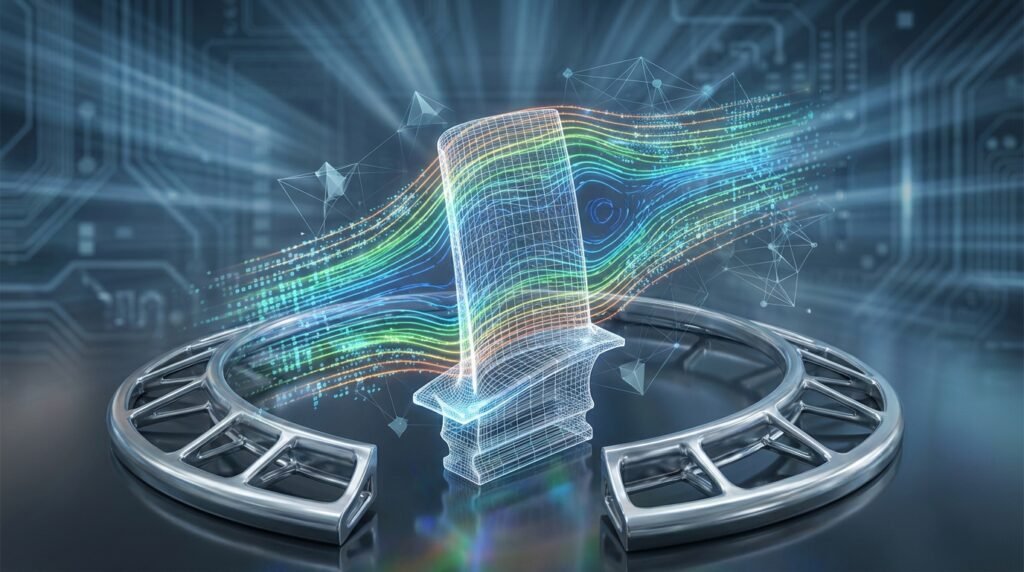
Image: A typical finite element mesh used for analysis, discretizing a complex geometry into smaller elements.
What is the Finite Element Method (FEM)?
At its core, FEM is a numerical technique for finding approximate solutions to boundary value problems for partial differential equations. In simpler terms, it’s a way to break down a complex engineering problem (like how a bridge deflects under load) into many smaller, simpler problems (how individual segments of the bridge behave).
Imagine trying to calculate the stress across an entire airplane wing. Directly solving the complex differential equations for the whole wing is incredibly difficult. FEM simplifies this by:
- Discretization: Dividing the complex geometry into a finite number of small, interconnected elements (the ‘finite elements’).
- Approximation: Using simple equations to approximate the behavior within each element.
- Assembly: Combining the solutions from all elements to approximate the solution for the entire structure.
This process transforms a continuous problem into a system of algebraic equations that computers can efficiently solve.
Key Concepts in the FEM Workflow
Understanding these fundamental steps is key to successful FEA:
1. Pre-processing: Setting Up the Problem
This is where you define your model and prepare it for analysis. Precision here prevents errors down the line.
- Geometry Creation/Import: Starting with a CAD model (from tools like CATIA or SolidWorks). Often, geometry simplification is needed to remove small features that are irrelevant to the analysis but would complicate meshing.
- Material Properties: Assigning realistic material data (Young’s modulus, Poisson’s ratio, density, yield strength, thermal conductivity, etc.) is critical.
- Meshing: This is the heart of discretization. You divide your geometry into a mesh of finite elements (e.g., bricks, tetrahedrons, shells, beams). Mesh quality (element shape, aspect ratio, skewness) directly impacts solution accuracy and convergence. Tools like MSC Patran or the meshing modules in Abaqus and ANSYS Mechanical are crucial here.
- Boundary Conditions (BCs) & Loads: These define how the model interacts with its environment. BCs constrain displacement or rotation (e.g., fixed supports, roller supports). Loads are the external forces, pressures, temperatures, or accelerations acting on the structure.
2. Solving: Crunching the Numbers
Once the model is fully defined, the solver takes over. Commercial solvers like Abaqus, ANSYS Mechanical, or Nastran are highly optimized for different types of analyses (linear, non-linear, static, dynamic, thermal, CFD, etc.). Open-source options like CalculiX also exist.
The solver assembles the element equations into a global system of equations and solves for the primary variables (e.g., nodal displacements in structural analysis). This involves large matrix operations.
3. Post-processing: Interpreting the Results
Raw data from the solver is usually massive and unreadable. Post-processors (integrated into most FEA software) help visualize and interpret the results effectively.
- Visualization: Contour plots (stress, strain, temperature), displacement plots, animation of deformation or vibration modes.
- Quantitative Analysis: Extracting numerical values at specific points, calculating reaction forces, performing safety factor checks, or generating reports.
Practical Applications of FEM Across Engineering Disciplines
FEM’s versatility makes it indispensable:
| Engineering Discipline | Common FEM Applications | Relevant Tools |
|---|---|---|
| Structural Engineering | Stress/strain analysis, deflection, vibration, buckling, fatigue, fracture mechanics (FFS Level 3). | Abaqus, ANSYS Mechanical, MSC Nastran |
| Aerospace Engineering | Aerostructural analysis, thermal management, fatigue life, composite material behavior. | Abaqus, ANSYS (Fluent/CFX for CFD), Nastran |
| Oil & Gas / Pressure Vessels | Fitness-for-Service (FFS) assessments, pipeline stress, offshore structure integrity, thermal cycling. | Abaqus, ANSYS Mechanical |
| Biomechanics | Medical implant design, bone stress, soft tissue mechanics, surgical planning. | Abaqus, ANSYS, specialized codes |
| Automotive Engineering | Crashworthiness, NVH (Noise, Vibration, Harshness), component durability, thermal management. | LS-DYNA, Abaqus, ANSYS, ADAMS (multibody dynamics) |
| Fluid Dynamics (CFD) | Flow simulation, heat transfer in fluids, aerodynamic/hydrodynamic forces (using FEM-based CFD codes). | ANSYS Fluent/CFX, OpenFOAM (for general CFD) |
Verification & Sanity Checks: Essential for Trustworthy Results
Just because a simulation runs doesn’t mean the results are correct. Rigorous verification is paramount.
- Mesh Sensitivity Analysis (Convergence Study): Run the same analysis with successively finer meshes. The key results (e.g., maximum stress, deflection) should converge to a stable value. If they don’t, your mesh might be too coarse or element quality poor.
- Boundary Condition & Load Path Checks: Does the model behave as expected under simple loads? Do reaction forces balance applied loads? Use simple ‘sanity checks’ (e.g., applying a known force to a simple beam and checking deflection against beam theory).
- Comparison with Analytical Solutions/Hand Calculations: For simplified cases or regions, compare FEA results with classical engineering formulas. This is invaluable for building confidence in your model setup.
- Material Model Sensitivity: How much do results change if material properties are slightly varied within their expected range?
- Real-World Validation: If possible, compare simulation results with experimental data or field observations. While this guide doesn’t involve performing experiments, it’s a critical step in a full engineering project.
Common FEM Mistakes and Troubleshooting Tips
Even experienced engineers make these sometimes. Being aware helps you avoid them:
1. Poor Mesh Quality
- Mistake: Using coarse meshes in high-gradient regions, elements with high aspect ratios, or distorted elements.
- Troubleshooting: Always check element quality metrics (skewness, aspect ratio, Jacobian). Refine mesh in areas of high stress concentration. Use different element types where appropriate (e.g., hex elements for uniform stress, tet for complex geometries).
2. Incorrect Boundary Conditions or Loads
- Mistake: Over-constraining (leading to artificial stiffness) or under-constraining (rigid body motion, non-convergence). Applying loads incorrectly (e.g., to the wrong face, wrong direction, or wrong magnitude).
- Troubleshooting: Visualize BCs and loads. Run a static check without loads to ensure the model is stable but not over-constrained. Compare reaction forces with applied loads. Consider real-world interactions carefully.
3. Material Model Mismatch
- Mistake: Using a linear elastic material model for a problem that involves significant plastic deformation or non-linear behavior.
- Troubleshooting: Understand the expected response of your material under the applied conditions. Use appropriate non-linear material models (plasticity, hyperelasticity) when necessary.
4. Ignoring Non-linearities
- Mistake: Assuming linearity (small deformations, linear materials, no contact) when the problem is inherently non-linear.
- Troubleshooting: Identify sources of non-linearity (geometric non-linearity from large deformations, material non-linearity, contact non-linearity). Enable non-linear solution procedures in your software.
Enhancing Your FEM Expertise
Becoming proficient in FEM takes practice and continuous learning. Here’s how you can deepen your skills:
- Master the Fundamentals: A strong grasp of solid mechanics, fluid mechanics, and numerical methods will make you a better FEA user.
- Hands-on Practice: Work through tutorials and example problems in your chosen software (Abaqus, ANSYS, etc.). Don’t just follow steps; try to understand the ‘why’ behind each action.
- Scripting & Automation: For repetitive tasks or complex model generation, learning Python for FEA (e.g., scripting Abaqus or ANSYS APIs) or MATLAB for custom pre/post-processing can be a game-changer. EngineeringDownloads.com offers downloadable Python scripts and templates that can help streamline your workflow.
- Stay Updated: Software capabilities evolve rapidly. Follow industry news, attend webinars, and read technical papers.
The Finite Element Method is a cornerstone of modern engineering design and analysis. By understanding its principles, mastering the practical workflow, and diligently performing verification and sanity checks, you’ll be well-equipped to tackle complex engineering challenges with confidence and precision.
Frequently Asked Questions about FEM
Further Reading
For deeper theoretical understanding, consult resources like academic texts or reputable engineering organizations. For example, the NAFEMS website offers extensive resources on simulation, analysis, and related topics.