Fatigue is a silent killer in structural engineering, responsible for a significant percentage of in-service failures across industries like aerospace, oil & gas, and civil infrastructure. Unlike sudden brittle fracture, fatigue damage accumulates gradually under cyclic loading, often without obvious warning signs until it’s too late. Understanding and accurately predicting fatigue life is therefore paramount for ensuring the long-term safety, reliability, and economic viability of any structure.
This comprehensive guide delves into the practical aspects of fatigue life prediction, offering structural engineers a clear, actionable roadmap. We’ll explore the fundamental concepts, common analytical methods, and the crucial role of Finite Element Analysis (FEA) in modern fatigue assessment workflows.

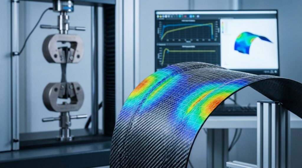
An illustrative S-N curve, a fundamental tool in fatigue life prediction. Source: Wikimedia Commons.
Understanding Fatigue: The Basics for Structural Engineers
Fatigue refers to the progressive, localized, and permanent structural damage that occurs when a material is subjected to cyclic or fluctuating stresses and strains. Even stresses well below the material’s yield strength can lead to fatigue failure if applied repeatedly over time.
Why is Fatigue Life Prediction Critical?
- Safety & Reliability: Preventing catastrophic failures in critical structures like aircraft components, offshore platforms, bridges, and pressure vessels.
- Economic Impact: Reducing costly downtime for repairs, inspections, and replacements.
- Design Optimization: Allowing engineers to design lighter, more efficient structures without compromising safety by accurately sizing components for cyclic loads.
- Regulatory Compliance: Meeting industry standards and codes (e.g., FFS Level 3 assessments in oil & gas) that mandate fatigue analysis for certain applications.
Key Factors Influencing Fatigue Life
Several variables significantly impact a material’s resistance to fatigue:
- Stress Amplitude: The range of stress variation is the most dominant factor. Higher stress amplitudes generally lead to shorter fatigue lives.
- Mean Stress: The average stress level around which the cyclic stress fluctuates. Tensile mean stress typically reduces fatigue life, while compressive mean stress can extend it.
- Material Properties: Different materials have inherently different fatigue resistances, characterized by their S-N (stress-life) or ε-N (strain-life) curves. Factors like ultimate tensile strength and ductility play a role.
- Surface Finish: Surface imperfections (scratches, machining marks, corrosion pits) act as stress concentrators, dramatically reducing fatigue life. Polished surfaces perform better.
- Environmental Conditions: Corrosive environments (e.g., saltwater) can accelerate crack initiation and propagation (corrosion fatigue). Extreme temperatures can also affect material behavior.
- Stress Concentrations: Geometric discontinuities (holes, fillets, sharp corners) create localized stress peaks that are prime sites for fatigue crack initiation.
Common Fatigue Life Prediction Methods
Engineers employ various approaches to predict fatigue life, each with its own advantages and suitable applications.
Stress-Life (S-N) Approach (High-Cycle Fatigue)
The S-N approach is widely used for high-cycle fatigue, where materials undergo a large number of cycles (typically > 10^4 to 10^5 cycles) at relatively low stress amplitudes (elastic range). It plots stress amplitude (S) against the number of cycles to failure (N) on a log-log scale.
- Key Concept: Assumes that fatigue damage is driven by stress.
- Data Source: Experimentally derived S-N curves for specific materials.
- Application: Welded structures, rotating machinery, components operating in the elastic regime.
- Limitations: Does not explicitly account for plasticity at crack initiation sites; sensitive to mean stress effects (often corrected using Goodman, Soderberg, or Gerber diagrams).
Strain-Life (ε-N) Approach (Low-Cycle Fatigue)
The ε-N approach is more appropriate for low-cycle fatigue, where high local strains (often plastic) occur, leading to failure in fewer cycles (typically < 10^4 to 10^5 cycles). It focuses on the total strain amplitude (elastic + plastic) versus cycles to failure.
- Key Concept: Fatigue damage is driven by local strain, especially plastic strain.
- Data Source: Experimentally derived ε-N curves.
- Application: Components experiencing localized plastic deformation, thermal fatigue, highly constrained regions.
- Advantages: More accurate for situations involving significant plastic deformation; naturally accounts for stress concentrations without needing a stress concentration factor.
Crack Propagation (Fracture Mechanics) Approach
Once a fatigue crack has initiated (or if a pre-existing flaw is present), fracture mechanics principles are used to predict its growth rate and the remaining life of the component until critical failure.
- Key Concept: Governed by the stress intensity factor range (ΔK) at the crack tip.
- Paris’ Law: A common empirical relationship:
da/dN = C (ΔK)^m, whereda/dNis the crack growth rate, C and m are material constants. - Application: Damage tolerance analysis, remaining life assessment, Fitness-for-Service (FFS) evaluations (e.g., API 579-1/ASME FFS-1).
- Challenge: Requires knowledge of initial crack size and geometry, which can be difficult to ascertain without non-destructive testing (NDT).
Comparison of Fatigue Prediction Methods
| Method | Focus | Typical Cycles | Key Advantage | Key Limitation |
|---|---|---|---|---|
| Stress-Life (S-N) | Nominal Stress | High (>10^5) | Simplicity, widely available data | Less accurate with local plasticity |
| Strain-Life (ε-N) | Local Strain | Low (<10^5) | Accounts for plasticity | Requires local strain calculation |
| Crack Propagation | Crack Growth | Post-initiation | Predicts remaining life with cracks | Requires initial crack assumption |
Practical Workflow: Fatigue Analysis Using FEA
Finite Element Analysis (FEA) has become indispensable for fatigue life prediction, especially for complex geometries and loading conditions where analytical solutions are impractical. Tools like Abaqus, ANSYS Mechanical, and MSC Nastran offer robust capabilities for integrated fatigue analysis.
Typical Steps in an FEA-Based Fatigue Workflow
- Geometry & Material Setup:
- Import or create the 3D CAD model. Simplify features that don’t impact stress significantly, but retain critical details (fillets, holes) where stress concentrations are expected.
- Assign appropriate material properties, including elastic modulus, Poisson’s ratio, yield strength, ultimate tensile strength, and crucially, fatigue material data (S-N or ε-N curves). Ensure data corresponds to the desired mean stress correction method.
- Meshing:
- Generate a suitable finite element mesh. Fine mesh density is critical in areas of high stress gradient or potential crack initiation (e.g., fillets, weld toes, bolt holes). Coarser mesh can be used in regions of low stress.
- Preferentially use higher-order elements (e.g., quadratic) for better stress accuracy.
- Load Cases & Boundary Conditions:
- Define all relevant cyclic loads (forces, pressures, displacements, thermal cycles) and their time histories.
- Apply realistic boundary conditions (fixed supports, constrained movements) that mimic the operational environment.
- Consider the sequence and phasing of multiple loads if they are not synchronous.
- Static/Transient Analysis:
- Perform a linear elastic or non-linear (if plasticity is significant) static structural analysis for each load peak/trough or a transient analysis for time-varying loads.
- Extract critical stress and strain results (e.g., Von Mises stress, principal stresses) from the FEA solution.
- Fatigue Post-Processing:
- Feed the FEA stress/strain results into a dedicated fatigue analysis module (e.g., ANSYS nCode DesignLife, Abaqus/Fe-Safe, HyperWorks Altair HyperLife).
- Specify the fatigue method (S-N or ε-N), mean stress correction theory (e.g., Goodman, Soderberg, Gerber, FKM, ASME Elliptic), and stress combination method (e.g., critical plane, maximum principal stress).
- Define load spectra (load event sequences, number of repetitions) or duty cycles.
- The software will then calculate accumulated damage using theories like Palmgren-Miner’s linear damage rule and predict the fatigue life (cycles to failure) or fatigue factor of safety.
- Results Interpretation:
- Visualize fatigue damage and life contours on the model. Identify critical locations and modes of failure.
- Analyze the sensitivity of the results to input parameters.
Verification & Sanity Checks in Fatigue Analysis
Trusting FEA results blindly can lead to catastrophic failures. Robust verification and validation are non-negotiable.
Essential Checks for Fatigue Analysis
- Mesh Sensitivity Study: Rerun analyses with finer meshes in critical areas to ensure results (especially stress concentrations) converge and are mesh-independent.
- Boundary Condition Review: Double-check that all constraints and supports accurately reflect the physical system. Incorrect BCs are a frequent source of error.
- Load Case Validation: Verify that applied loads, their magnitudes, and directions are correct and represent the operational environment. Compare with design specifications or field measurements.
- Convergence Criteria: For non-linear or transient analyses, ensure the solver has met its convergence criteria adequately.
- Analytical Hand Calculations: Perform simplified hand calculations for basic load cases or critical sections (e.g., using beam theory, stress concentration factors from charts) to establish a baseline for comparison.
- Fatigue Material Data Review: Confirm that the S-N or ε-N curves used are appropriate for the material, processing, and environmental conditions. Extrapolating data too far can be risky.
- Sensitivity Studies: Vary key input parameters (e.g., material properties within tolerances, load magnitudes, geometry dimensions) to understand their impact on predicted life. This helps identify design robustness.
- Experimental Validation (if possible): Compare FEA predictions with fatigue test data from prototypes or similar components. This is the ultimate validation.
Common Mistakes in Fatigue Analysis and How to Avoid Them
Even experienced engineers can fall into common traps. Being aware of these pitfalls helps in delivering more reliable analyses.
- Ignoring Mean Stress Effects: Failure to apply appropriate mean stress corrections can significantly over- or under-predict fatigue life, especially under tensile or compressive mean stresses.
- Using Incorrect Material Data: Material fatigue properties are sensitive to manufacturing processes, heat treatment, and temperature. Generic handbook data might not be representative. Always seek specific data for the actual material condition.
- Poor Mesh Quality in Critical Regions: Coarse meshes or elements with high aspect ratios in areas of high stress gradients will yield inaccurate stress peaks, leading to incorrect life predictions.
- Neglecting Surface Finish and Residual Stresses: A rough surface or tensile residual stresses (e.g., from welding or machining) can drastically reduce fatigue life. These factors must be accounted for.
- Over-reliance on Safety Factors: While safety factors are essential, they are not a substitute for thorough analysis. Blindly applying a large safety factor might lead to an over-designed, heavy, and costly component.
- Misinterpreting Stress Concentrations: Stress concentration factors from analytical solutions are for specific geometries. In FEA, the peak stress needs careful interpretation, especially for singularity-like conditions at sharp corners, and not just directly multiplied by a global stress.
- Not Considering Load Sequence/Variable Amplitude Loading: For complex operational profiles, simply summing damage based on constant amplitude S-N curves might be insufficient. Cycle counting algorithms (e.g., Rainflow counting) are crucial for variable amplitude loading.
- Ignoring Crack Initiation vs. Propagation: Confusing the prediction of crack initiation life with total life (initiation + propagation) can lead to non-conservative designs if a crack is assumed to be acceptable.
Tips for Robust Fatigue Design and Analysis
- Minimize Stress Concentrations: Design with generous radii, avoid sharp corners, and smooth transitions in geometry.
- Material Selection: Choose materials with good inherent fatigue strength and ductility. Consider specialized fatigue-resistant alloys where appropriate.
- Surface Treatments: Explore techniques like shot peening, case hardening, or polishing to improve surface integrity and introduce compressive residual stresses.
- Weld Design & Post-Processing: For welded structures, focus on fatigue-optimized weld designs, careful inspection, and post-weld treatments (e.g., toe grinding, peening) to improve fatigue performance.
- Comprehensive Load Spectrum Definition: Invest effort in accurately defining the full range of operational loads and their frequency of occurrence.
- Leverage Automation: For repetitive fatigue analyses or parametric studies, scripting with Python or MATLAB can automate model setup, load application, result extraction, and post-processing, saving significant time and reducing manual errors.
- Expert Consultation: For complex fatigue analysis projects or to deepen your expertise, EngineeringDownloads offers project consultancy and online courses tailored for engineers.
- Regular Inspection & Monitoring: Implement NDT techniques and structural health monitoring programs for in-service components, especially in critical applications like aerospace or offshore structures.
Conclusion
Fatigue life prediction is a multifaceted discipline crucial for modern structural engineering. By combining a solid theoretical understanding with advanced numerical tools like FEA, engineers can move beyond conservative estimations to deliver safe, efficient, and durable designs. Mastering these methods, understanding their limitations, and performing diligent verification are the hallmarks of robust structural integrity assessment.
Further Reading
NREL Technical Report: Fatigue Life Prediction for Wind Turbine Blades