Composite Pressure Vessels: The Ultimate Guide to Manufacturing and Simulation
Composite Pressure Vessels are revolutionizing how we store high-pressure fluids. They offer incredible strength at a fraction of the weight of traditional steel tanks. In this friendly yet professional guide, we’ll explore what composite pressure vessels are, why they’re superior in many ways, how they’re made (filament winding and more), and how to simulate their behavior using software like Abaqus and ANSYS. Along the way, we’ll highlight practical examples and resources to help you design and analyze composite pressure vessels with confidence. Let’s dive in!
What Is a Composite Pressure Vessel?
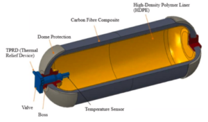
A composite pressure vessel is a container made of fiber-reinforced polymers (composite materials) designed to hold gases or liquids at high pressure. Instead of solid metal walls, these vessels use a thin inner liner (often metal or plastic) wrapped with strong fiber (like carbon or glass) embedded in resin. This construction yields an exceptional strength-to-weight ratio – composite pressure vessels are much lighter than equivalent metal tanks while still safely holding high pressures. They also boast advantages like corrosion resistance, good sealing (no leaks), and high reliability, making them ideal for many applications.
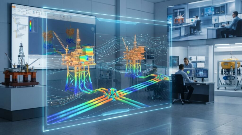
Where are composite pressure vessels used? You’ve probably encountered them in various industries: for example, compressed natural gas (CNG) tanks in cars (those lightweight cylinders in trunk of CNG vehicles), hydrogen fuel tanks in cutting-edge automobiles and buses, scuba diving tanks, and even spacecraft oxygen tanks. Their lightweight nature and durability make them popular in aerospace and automotive fields where reducing weight is crucial for efficiency. Chemical plants and energy storage systems also use composite vessels to store corrosive or high-pressure fluids safely without risk of rust.
Why choose composites over metal? Let’s summarize the key advantages of composite pressure vessels versus traditional metal ones:
- Lightweight: Composites are far lighter, enabling easier transportation and higher payloads (great for vehicles and spacecraft).
- High Strength-to-Weight: Pound for pound, composite materials (like carbon fiber) can be stronger than steel. This means a thin-walled composite can handle the same pressure as a thick heavy steel wall.
- Corrosion Resistance: No rust here – composites don’t corrode like metals. This is excellent for storing chemicals or humid gases.
- Safety: Properly designed composite vessels can be safer in failure mode. Instead of exploding, some composite vessels tend to split or leak gradually, reducing explosion risk. They also have lower leakage over time due to the liner.
- Thermal Insulation: Polymer liners and composite walls can insulate contents better than metal, which can be useful for certain cryogenic or hot fluid applications.
Of course, composites come at a higher manufacturing cost and require careful quality control and certification. But for many modern applications, the benefits outweigh these challenges.
How Are Composite Pressure Vessels Made?
Most composite pressure vessels are made by a process called filament winding, which is the primary manufacturing method for these structures. In filament winding, bands of continuous fiber (such as carbon or glass fiber) impregnated with resin are wound around a rotating mandrel (form) in specific patterns. The mandrel provides the shape of the vessel – for example, a metal or plastic liner shaped like a cylinder with domed ends. As the mandrel spins, a computer-controlled machine lays down fibers at a set angle, wrapping the vessel layer by layer (almost like high-tech “spiderweb knitting” of the tank). Once the required thickness is achieved, the resin is cured (hardened) – often by heating the whole assembly in an oven.
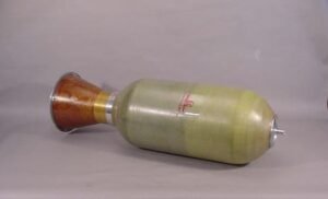
A composite pressure vessel example – a fiberglass composite overwrapped pressure container (in this case, a rocket motor casing) showing the fiber winding layers. Such composite vessels use a thin liner (metal or plastic) with an outer wrap of resin-impregnated fibers for strength.
Key aspects of filament winding for pressure vessels include the winding angle and layer pattern. The fibers can be laid in different orientations:
- Hoop winding (circumferential): Fibers are wrapped around the circumference (90° relative to the cylinder’s axis). This provides maximum hoop strength to resist internal pressure.
- Helical winding: Fibers are laid at an angle (e.g. ±30° to ±60°) in a crisscross helical pattern along the vessel. Helical layers add longitudinal strength (along the length of the cylinder) in addition to hoop strength.
- Polar or Dome winding: Special patterns cover the domed end caps of the vessel. As fibers transition from the cylinder body to the domes, the angle continuously changes to cover the hemisphere shape.
Geodesic vs. isotensoid patterns: In advanced composite vessel design, you’ll hear terms like geodesic, semi-geodesic, and isotensoid winding for dome sections:
- Geodesic winding assumes zero friction so fibers take the shortest path on the dome (a geodesic path). It’s efficient but in reality some friction exists.
- Semi-geodesic winding accounts for friction, meaning fibers don’t freely slide and the pattern differs slightly.
- Isotensoid winding is a special design where the dome shape itself is contoured so that all fibers carry equal tension (stress) when the vessel is pressurized. An isotensoid shape, if wound correctly, leads to an optimally strong vessel with minimal material – it’s like an ideal shape for a pressure vessel dome such that no fiber is overstressed or understressed. Isotensoid designs are more complex but very material-efficient.
Manufacturers choose the winding pattern and angles to best handle the stresses from internal pressure. Often, there is a mix of hoop layers and helical layers to balance strength in all directions. After winding, the composite is cured, and the vessel may undergo an autofrettage process – pressurizing it beyond operating pressure once to plastically deform the liner slightly, which leaves beneficial residual stresses that improve fatigue life (the metal or plastic liner ends up compressed by the fiber overwrap).
Liner materials: Composite Overwrapped Pressure Vessels (COPVs) are classified by “Type”. For example, Type III vessels have a metal liner (usually aluminum or steel) wrapped in composite, and Type IV vessels have a plastic liner (like HDPE, PA, or other polymers) wrapped in composite. Type IV are the lightest because the liner is lightweight and non-structural (it only provides a leak-tight barrier), whereas the composite bears all the load. Type IV composite vessels are increasingly popular for fuel tanks (CNG, hydrogen) because they offer the lowest weight for a given pressure capacity. In contrast, all-metal tanks are Type I, and there are hybrid types II and III with partial wraps. Choosing liner material involves trade-offs: plastic liners weigh less and don’t corrode, but they can be permeable to gas and not as strong as metal, so the design must ensure the composite carries the load fully.
Designing a Composite Pressure Vessel
Designing a composite pressure vessel involves determining the right materials and layup to meet strength requirements. Engineers must consider:
- Materials: Common fibers are carbon fiber (highest strength and stiffness, but expensive), glass fiber (cheaper, more flexible), or aramid (Kevlar, tough). The matrix is usually epoxy resin or similar. Often carbon/epoxy is used for high-performance vessels (like hydrogen tanks) due to superior properties. The liner could be aluminum, or plastics like HDPE, PET, or polypropylene – chosen for compatibility with the fluid (e.g., ammonia compatibility, hydrogen embrittlement avoidance).
- Layup (stacking sequence): How many layers at each angle. For example, a design might specify something like a sequence [90° / ±45°]_n (hoop and helical layers repeated n times). The sequence and material fractions determine the strength in hoop vs longitudinal directions. In one study, different stacking sequences were tested to see which minimized stress and damage in an ammonia tank; e.g. a sequence [90/±30/90]_3 was found effective in lowering stress in the liner.
- Thickness: The total composite thickness needed to hold the pressure with a safety factor. This can be calculated using lamina theory and known strength of fibers, then refined with simulations.
- Dome shape: Whether a standard shape (elliptical, spherical cap) or an isotensoid profile for optimal stress distribution. Many high-end designs use isotensoid domes to maximize performance.
- Boss and attachments: The ends of the vessel usually have metal bosses (where valves or pipes attach). These need reinforcement, and sometimes extra layers or a different fiber orientation around openings to prevent weakness.
Analytical design of composite vessels can be quite complex, involving classical laminate theory and netting analysis for the wound layers. Often, designers will do preliminary calculations to choose a layup, then turn to simulation tools for detailed analysis and fine-tuning. That’s where our next section comes in – using FEA software to simulate these vessels.
Simulation of Composite Pressure Vessels (FEA Analysis)
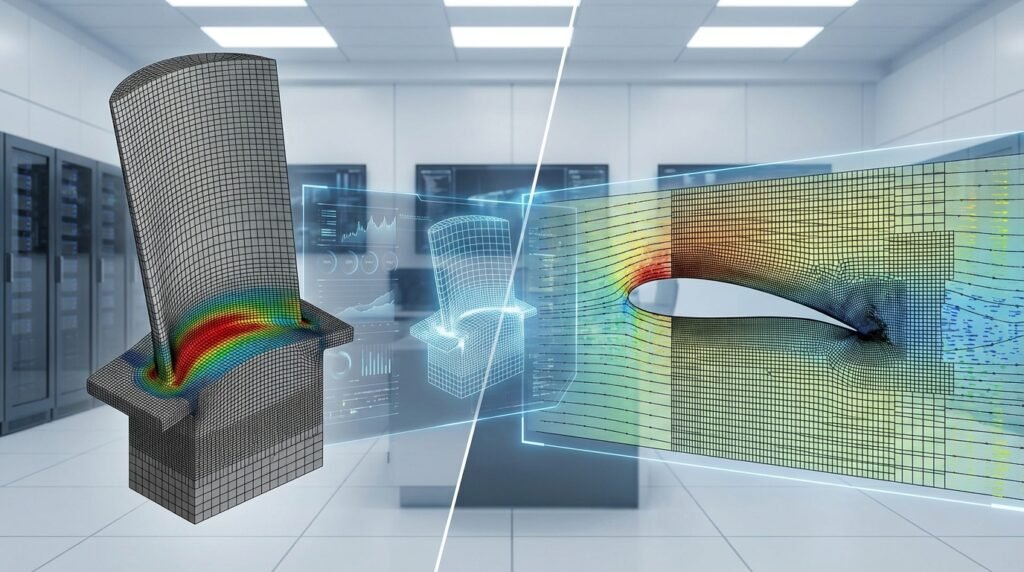
Simulating a composite pressure vessel means using Finite Element Analysis (FEA) to predict stresses, strains, and potential failure in the vessel under pressure (and possibly other loads like temperature or impact). Because composites are anisotropic (properties depend on fiber direction) and the fiber orientation varies across the vessel, simulation is extremely helpful to capture all these details that hand calculations might miss.
FEA Tools: Two of the most popular general-purpose FEA software for composite vessel analysis are Abaqus and ANSYS, so we’ll focus on those. There are also others like Nastran, LS-DYNA, etc., but the concepts are similar.
Abaqus for Composite Pressure Vessels
Abaqus is well-known for its powerful material modeling capabilities and scripting. In Abaqus/CAE, you can model the vessel geometry and define composite layups. However, one challenge is specifying the varying fiber orientation on a curved dome. There are two main approaches to simulate a filament-wound vessel in Abaqus:
- Manual (GUI-based) modeling: You partition the vessel geometry (especially the dome) into many slices, and assign each partition a local material orientation and thickness corresponding to the winding angle at that region. For example, near the equator of the dome the fiber angle might be 20° from horizontal, changing continuously to 90° at the very top – you’d approximate this by many small regions. This method can work for simple layups but is time-consuming and prone to error. It’s easy to make mistakes or end up with discontinuities between partitions.
- Python scripting (automation): This is the preferred approach for complex windings. Abaqus allows you to use Python scripts to create your model. A script can mathematically define how the fiber angle and thickness vary over the dome and automatically assign each element a correct orientation. For instance, one could write a script to compute the geodesic or isotensoid winding path and apply a different orientation to every element of the mesh – something nearly impossible to do by hand. Python automation yields a highly accurate model that truly reflects the continuous variation of fiber angles, and it saves a ton of manual labor. In fact, advanced simulation packages provide such scripts or plugins. (In one of our training packages, we demonstrate automated isotensoid dome simulation with Python scripting, so you can simulate an entire vessel with just a few clicks!)
Another powerful aspect of Abaqus is the ability to include user subroutines for custom material behavior. For composite failure analysis, you might implement a user-defined material (UMAT) to incorporate a specific failure criterion like the Puck theory for damage evolution. Abaqus’s flexibility means you can go beyond built-in options when high fidelity is needed.
From an analysis perspective, a typical Abaqus simulation of a composite vessel will involve applying internal pressure to the inner surface of the vessel model (with the liner and composite modeled, often with tie constraints binding them). You’d use layered shell elements or 3D continuum plies to model the composite. Then you’d check results like stresses in the liner (usually using von Mises stress for yielding) and stresses/strains in each composite layer. Abaqus can directly compute failure indices for criteria like Tsai-Wu or Hashin, if you input those material allowables. For more advanced criteria like Puck (which distinguishes fiber and inter-fiber failure modes), a UMAT is used, as mentioned. The output tells you if any layer is failing under the load, and where. You can then iterate your design (change fiber angles, add layers, etc.) to meet safety factors.
ANSYS for Composite Pressure Vessels
ANSYS also offers robust tools for composite analysis. In particular, ANSYS ACP (Ansys Composite PrepPost) is a dedicated module that makes defining layered composites more intuitive. Using ACP or the built-in engineering data, you can specify plies, fiber orientations, and stacking sequences on your 3D model of the vessel. ANSYS then takes care of assigning the correct properties to each element.
For a pressure vessel, one might use shell elements in ANSYS with each ply orientation defined. You could, for example, create a model of the cylindrical section and domes and then layup, say, 12 plies: some hoop, some helical, etc., using the ACP interface. The tool allows you to simulate complex winding patterns too – you can import a fiber path or use a script to vary orientation gradually across the dome if needed.
ANSYS’s solver will compute stresses in each ply and can evaluate failure criteria like Tsai-Hill, Tsai-Wu, or Hashin for each layer. These are built-in, making it straightforward to predict first-ply failure pressure (the pressure at which the first layer in the laminate would start to fail) and overall burst pressure. You can also simulate progressive failure by degrading properties of failed plies in multiple load steps, to see how the vessel might fail progressively.
Both Abaqus and ANSYS can incorporate nonlinear effects (large deformations, plasticity in the liner, etc.) and even thermal effects if you need to check performance across temperature ranges. For example, a cryogenic vessel for liquid hydrogen might need analysis at very low temperatures to ensure the liner doesn’t crack and the composite retains strength.
Other Simulation Considerations
- Buckling: Composite vessels under external pressure (or even internal, if very thin) might need a buckling check. FEA can perform an eigenvalue buckling analysis to ensure stability (relevant for things like submarine hulls or outer space vacuum).
- Impact and Crash: Sometimes it’s important to simulate drop or impact on the vessel (e.g., a gas tank in a car accident). Explicit FEA solvers can model impact damage in composites.
- Fatigue life: Repeated pressure cycles can cause fatigue. While composites don’t fatigue the same way metals do, you’d examine stress ratios and maybe do a simplified fatigue life estimate for the liner and composite (using S-N curves for the liner, and a stiffness degradation approach for composite).
- Crack simulation: For metal vessels, fracture mechanics is crucial. In composites, cracks can occur in the matrix or delamination between layers. While a properly made composite vessel is intended to be crack-free, advanced simulations using XFEM (Extended Finite Element Method) can model crack growth in vessel structures. For instance, we offer a specialized example of simulating crack growth in a pressure vessel using Abaqus XFEM, which shows how a crack initiates and propagates under cyclic pressure – an important consideration for damage tolerance (see our package “[Simulation of XFEM Crack Growth in a Pressure Vessel using Abaqus]” for a step-by-step tutorial). This kind of simulation is valuable if you need to assess the “what if” scenario of a flaw in your vessel.
- Fluid-Structure Interaction (FSI): Sometimes, the fluid inside can slosh or apply dynamic loads (especially if it’s a cryogenic fluid that might rapidly boil-off, etc.). Tools exist to co-simulate fluid and structural behavior, though for most static pressure cases, treating pressure as static is sufficient.
Failure Criteria for Composite Vessels
Designing a composite pressure vessel isn’t just about not breaking it immediately – we also care about how and when it fails. Composites have complex failure modes: fibers can break (fiber failure in tension or compression), or the matrix can crack or shear (matrix failure, sometimes called inter-fiber failure). Unlike ductile metal that yields noticeably, composites can have a sudden brittle failure if not designed with the right safety margins.
To predict failure, engineers use several failure criteria:
- Tsai-Hill / Tsai-Wu: These are quadratic interaction criteria that give a failure index based on the combined stresses in a ply. If the index ≥ 1, the ply is predicted to fail. They’re relatively simple and widely available in FEA software. Tsai-Wu, for example, considers different strengths in tension and compression and provides an interaction of those stresses.
- Hashin’s Criteria: Hashin criteria distinguish the mode of failure (fiber tension, fiber compression, matrix tension, matrix compression) with separate formulas. It’s a bit more detailed than Tsai-Wu and often considered more accurate for identifying how a composite fails.
- Puck Criterion: An even more advanced criterion, Puck’s theory, is specialized to predict matrix-dominated failures with high accuracy. It can differentiate between various fracture angles in the matrix. Puck’s criterion is highly regarded for its realistic predictions, but it’s not built into most software by default – in Abaqus, as mentioned, you might implement it via a UMAT (user subroutine). If you’re doing a very high-stakes design (like a spacecraft COPV that must not fail), such advanced criteria could be warranted.
Using these criteria in simulation, you can estimate the burst pressure of the vessel. For example, you gradually increase internal pressure in the model until a failure index in any ply reaches 1 (first ply failure). Beyond that, if doing progressive analysis, you’d degrade that ply’s stiffness and continue until the vessel can’t sustain load (burst). Many designs aim for a burst pressure that is at least 2.5 times the operating pressure (per standards like ISO or ASME guidelines for composites).
Also, don’t forget the liner – if it’s metal, check its yield (we often allow the metal liner to yield a bit at burst – that’s okay as long as the fibers carry the load). If it’s plastic, ensure the strain is within safe limits (plastics can creep or crack if overstressed or exposed to chemicals).
Case Study: Composite Vessel for Ammonia Storage (Real-Life Example)
To tie everything together, let’s consider a real-world case. Ammonia is being explored as a hydrogen carrier fuel, and it needs to be stored under pressure in vehicles. Suppose we want to design a Type-IV composite pressure vessel for liquefied ammonia (which is similar to a CNG tank design). Key points would be:
- Choose a liner material compatible with ammonia (say, polypropylene liner because it resists ammonia and is lightweight).
- Choose composite wrap (carbon fiber for high strength, maybe some glass fiber to save cost).
- Determine the dimensions to hold the required volume, and design the laminate such that it can handle both the internal pressure and potential impacts (drop tests).
- Use FEA to analyze the stresses: ensure the liner’s von Mises stress is below yield at operating pressure, and composite plies have failure index < 1 by a good margin.
- Iterate material choices: maybe test PET vs PP liner in simulation, or carbon vs glass wrap, to see weight and stress differences. (One study found PP liners gave lower stress than PET for a given design, and carbon fiber wraps had higher safety margin than glass – pointing to PP+Carbon as an optimal combo for that project.)
In fact, we offer a complete tutorial package on analysis and validation of a composite pressure vessel for ammonia storage where all these steps are carried out in detail. It includes the Abaqus model, the CAD geometry, and a full report with step-by-step instructions and results. This kind of resource is invaluable if you want to learn by example – you can follow the workflow and even adapt the model to your own project. (If interested, check out “Analysis and Validation of a Composite Pressure Vessel for Liquefied Ammonia Storage” on our site for a deep dive into that project.)
Best Practices for Simulation and Design
Before we wrap up, here are some best practices and tips when dealing with composite pressure vessels:
- Understand the load cases: Internal pressure is the main one, but consider temperature loads (thermal expansion of liner vs composite can cause stress), external pressure if applicable, and dynamic loads if the vessel is mobile.
- Mesh carefully: For FEA, use a sufficiently fine mesh, especially in the dome region where stresses peak. Layered elements should have at least one element per ply if using shell elements (or use equivalent smeared properties). Check that the fiber orientation is assigned correctly – a common mistake is getting the angle reference wrong, leading to an unrealistic simulation.
- Validation: If possible, validate your simulation with an analytical solution or a known case. For instance, netting theory can approximate the required fiber amount – does your FEA result roughly agree? If an experimental burst test result is available from literature for a similar vessel, compare your safety margins.
- Factor in manufacturing realities: Filament winding can have slight gaps, overlaps at the helical turnaround points, etc. These are hard to model explicitly, but be aware that real strength might be a few percent lower than an ideal model. Apply a knock-down factor for safety.
- Check codes and standards: Standards like ASME BPVC Section X (for fiber-reinforced plastic pressure vessels) or ISO 11515 for composite cylinders provide design requirements (like burst factors, test procedures). Make sure your design complies if it’s for real-world use.
- Progressive failure vs first ply: Decide if your design is “fail-safe”. Many composite vessels are designed such that even if one layer fails, the whole vessel doesn’t burst immediately. This means adding a bit of extra material so that after first ply failure, the remaining plies can still hold pressure for a while. It’s a toughness approach to give leak-before-burst behavior.
Engineering Downloads – How We Can Help You
Designing and simulating composite pressure vessels can be challenging, especially if you’re doing it for the first time or tackling a new aspect like crack growth or a novel material. That’s where Engineering Downloads comes in to support you:
- We offer ready-to-use simulation packages and tutorials developed by experts. As mentioned, if you want to learn XFEM crack growth in pressure vessels, our step-by-step Abaqus tutorial on that topic will save you weeks of trial and error. Similarly, our composite ammonia tank analysis package provides a real example of designing a Type IV COPV from start to finish, which you can use as a template for your own project.
- We have training courses for Abaqus, ANSYS, and other tools focusing on practical applications like composite structural analysis. For instance, our Abaqus Composite Analysis Training Pack covers not just pressure vessels but other composite structures (beams, plates, etc.), teaching you how to set up material orientations, apply failure criteria, and interpret results.
- On our blog and resources section, you’ll find free tips and articles (just like this one!) on various simulation topics – from meshing techniques to scripting and beyond – all aimed at making you proficient in CAE (Computer-Aided Engineering).
And if you need more personalized help…
Consultation Services – Get Expert Help
Every engineering project is unique. You might face specific questions like “What’s the best fiber orientation for my custom vessel shape?” or “How do I include impact damage in my simulation?” When you need tailored advice, our consultation services are here for you. We provide one-on-one consulting with experienced simulation engineers who have designed pressure vessels and composite structures for industry and research. We can help with tasks such as:
- Reviewing your vessel design and suggesting improvements or weight reduction strategies.
- Setting up complex simulations (we can even build the FEA model for you or with you, via screen-sharing workshops).
- Interpreting FEA results and correlating them with test data or standards.
- Troubleshooting analysis issues (for example, if your simulation isn’t converging or a subroutine isn’t working, we’ll figure it out).
Our goal is to be a partner in your engineering success – whether you’re a student working on a thesis, an engineer designing a new product, or a company seeking to train your team in advanced simulation techniques.
Feel free to reach out to us for any questions or project needs in this field. Composite pressure vessels are an exciting area of engineering with lots of innovation happening (from linerless tanks to new fiber materials), and we’re passionate about staying at the cutting edge and helping our community do the same.
Conclusion and Key Takeaways
Composite pressure vessels represent the future of high-pressure storage – they are lightweight, strong, and adaptable to many needs. In this guide, we covered what they are, how they’re made via filament winding, and how to analyze them using modern FEA tools. The key points to remember are:
- Materials & Construction: Combining a liner with fiber-resin overwrap yields high performance. Carbon fiber composites can drastically cut weight vs metal tanks, enabling applications like hydrogen vehicles and space systems.
- Manufacturing: Filament winding allows precise placement of fibers. The winding patterns (hoop, helical, geodesic, isotensoid) are critical to achieving a vessel that carries pressure evenly. Advanced designs use isotensoid dome shapes for optimal stress distribution.
- Simulation: Tools like Abaqus and ANSYS can accurately simulate composite vessels. Use scripting or specialized composite modules to capture the varying fiber orientations. Always check multiple failure criteria to ensure safety.
- Design Safety: Employ proper safety factors and consider failure modes. Aim for leak-before-burst by design if possible. Validate your simulation results against theoretical expectations or standards.
- Resources: Don’t go it alone – leverage available tutorials, example models, and expert consultation (we’re happy to help!) to accelerate your learning and project success.
We hope this comprehensive guide has demystified composite pressure vessel design and simulation for you. Whether you plan to model a simple CNG tank or an advanced aerospace COPV, the combination of sound engineering principles and powerful software tools will enable you to achieve a safe and efficient design. Happy innovating, and remember – if you need any assistance, the Engineering Downloads team has got your back.
Feel free to explore our related packages (like the XFEM crack growth simulation or the ammonia tank analysis mentioned above) and get in touch for any custom consulting needs. Good luck with your composite pressure vessel projects!