CATIA (Computer Aided Three-dimensional Interactive Application) is a cornerstone in the world of engineering design and manufacturing. Developed by Dassault Systèmes, it is much more than just a CAD software; it is a comprehensive multi-platform suite for computer-aided design, computer-aided manufacturing (CAM), computer-aided engineering (CAE), 3D product lifecycle management (PLM), and more. For engineers across diverse disciplines, CATIA provides an unparalleled environment to conceptualize, design, analyze, and deliver innovative products.

Image: An illustrative view of the CATIA V5R18 user interface.
Unveiling CATIA’s Core Capabilities
CATIA’s strength lies in its integrated approach, offering a vast array of workbenches tailored for specific tasks. This ensures a seamless flow from initial concept to final production.
Product Design (CAD)
- Part Design: The fundamental workbench for creating solid models from sketches. Essential for designing individual components with features like pads, pockets, holes, and fillets.
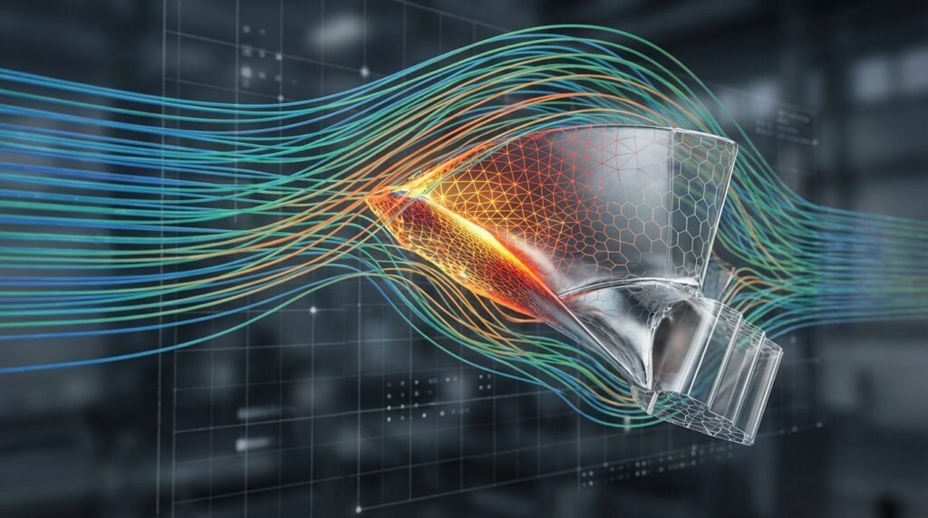
- Generative Shape Design: Crucial for complex surfacing and styling, often used in automotive body panels, aerospace components, and consumer products where aesthetics and aerodynamics are paramount.
- Assembly Design: Enables engineers to integrate multiple parts, apply constraints, and analyze the kinematic behavior of complex assemblies.
Manufacturing (CAM)
- NC Machining: Allows for the definition of tool paths for various machining operations (milling, turning, drilling) directly from the 3D model, ensuring precision and reducing manufacturing lead times.
- Sheetmetal Design: Specialized tools for designing sheet metal parts, including flattening for manufacturing, bend allowances, and tooling considerations.
Engineering Analysis (CAE)
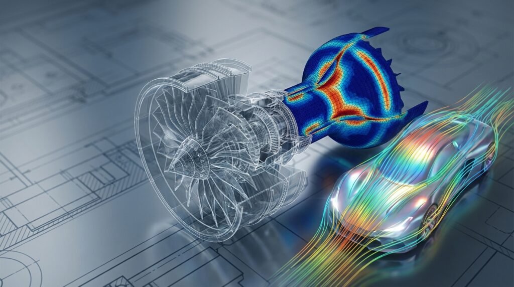
- Generative Structural Analysis: CATIA offers integrated Finite Element Analysis (FEA) capabilities for preliminary stress, displacement, and modal analyses. This allows designers to perform quick sanity checks without leaving the CATIA environment.
- Kinematics: Simulates the motion of mechanisms and assemblies, helping to detect interferences and optimize movement.
Why CATIA Stands Out for Engineers
CATIA’s robust features make it a preferred choice for leading industries:
- Integrated Platform: A single environment for CAD, CAM, and CAE streamlines the design process and minimizes data translation errors.
- Parametric and Associative Design: Changes made to a design automatically propagate through associated drawings, assemblies, and even analyses, ensuring consistency.
- Multidisciplinary Approach: Supports a wide range of engineering disciplines, fostering collaboration across teams.
- Industry Adoption: Widely used in aerospace, automotive, shipbuilding, and industrial equipment sectors, making it a valuable skill for engineers.
Getting Started with CATIA: A Practical Workflow
A systematic approach ensures efficient and error-free design.
Setting Up Your Environment
- Project Structure: Create dedicated folders for parts, assemblies, and drawings. Maintain clear naming conventions.
- Units and Standards: Configure units (e.g., mm, inches) and drafting standards (e.g., ISO, ANSI) at the start of each project.
- Template Files: Utilize or create standard part, assembly, and drawing templates to save time and ensure consistency.
Sketching Essentials for Part Design
Sketching is the foundation of 3D modeling in CATIA.
- Fully Constrained Sketches: Always aim for fully constrained sketches (green in CATIA) to ensure predictable behavior and robust designs.
- Dimensional Constraints: Use smart dimensions to control size and position.
- Geometrical Constraints: Employ tangency, parallelism, perpendicularity, coincidence, and symmetry for precise relationships between sketch elements.
- Common Mistake: Leaving sketches under-constrained leads to unpredictable changes and rework.
Part Modeling Best Practices
Building robust and modifiable 3D parts.
- Feature Order: Build features logically. Start with base features, then add details. Keep related features grouped.
- Parent/Child Relationships: Understand how features depend on each other. Deleting a parent feature will affect its children.
- Avoid Hard-Coding: Use parameters and formulas where possible to drive dimensions and features, enabling easy design modifications.
Assembly Design & Management
Bringing components together.
- Component Placement: Insert components and use the ‘Manipulation’ tool to position them roughly.
- Assembly Constraints: Apply constraints (coincidence, contact, offset, angle) to define precise relationships between parts.
- Bill of Material (BOM): Generate accurate BOMs directly from the assembly structure.
- Takeaway: Start with fixed components and build up the assembly structure systematically.
Drawing Generation
Communicating your design.
- Views: Create main views (front, top, side), isometric views, and section views.
- Annotations: Add dimensions, tolerances, surface finishes, and notes.
- Title Block: Ensure all relevant project and company information is correctly populated.
CATIA in Advanced Engineering Workflows
CATIA’s strength extends into sophisticated engineering processes.
CAD-CAE Integration: Preparing Models for Analysis
While CATIA has built-in FEA, models often need to be exported to dedicated CAE tools like Abaqus, ANSYS Mechanical, or MSC Nastran for more complex analyses (e.g., non-linear, dynamic, explicit, or CFD with tools like Fluent/CFX or OpenFOAM).
- Simplification: Remove small features, fillets, and holes that are insignificant for the analysis but add meshing complexity.
- Mid-Surfacing: For thin-walled structures, create mid-surfaces to generate 2D shell elements, significantly reducing computational cost.
- Idealization: Represent bolts as beam elements or stiffeners as 1D elements.
- Data Exchange: Export models using standard formats like STEP or IGES. Some CAE tools offer direct interfaces for CATIA models.
Design for Manufacturing (DFM)
CATIA tools facilitate DFM by allowing engineers to analyze designs for manufacturability early in the process.
- Draft Analysis: Check if parts can be easily removed from molds.
- Wall Thickness Analysis: Identify areas that are too thin or too thick, which can lead to manufacturing defects.
Generative Design & Optimization
CATIA’s Generative Design capabilities (part of the 3DEXPERIENCE platform) allow for topology optimization, where the software suggests optimal material distribution based on load cases and boundary conditions. This can lead to lightweight and highly efficient designs.
Common Challenges and Troubleshooting Tips
Even seasoned engineers encounter issues. Here’s how to tackle them:
| Challenge | Root Cause | Troubleshooting Tip |
|---|---|---|
| Sketcher errors | Under-constrained or over-constrained sketch | Use ‘Sketch Analysis’ to identify issues. Delete redundant constraints or add missing ones. |
| Feature regeneration failure | Parent feature modified or deleted; circular reference | Check the ‘Update’ icon in the specification tree. Use ‘Show Parent/Children’ to trace dependencies. |
| Assembly constraints not working | Components are fixed; conflicting constraints | Ensure components are not ‘fixed’ if they need to move. Suppress conflicting constraints one by one to isolate the issue. |
| Performance slowdown | Complex models; large assemblies; insufficient hardware | Use ‘Lightweight’ representations for large assemblies. Hide unnecessary components. Upgrade RAM or graphics card. |
| Data exchange issues | Format incompatibility; corrupted file | Try different export formats (e.g., STEP AP203 vs. AP214). Check original file integrity. |
Verification and Sanity Checks in CATIA Design
Before releasing a design, thorough checks are essential.
- Interference Checks: Run ‘Clash Analysis’ in Assembly Design to detect any overlaps between components, critical for ensuring fit and function.
- Mass Properties Verification: Calculate mass, center of gravity, and moments of inertia. Compare against hand calculations or known values for similar components.
- Design Review Checklists:
- Are all dimensions and tolerances clearly defined?
- Are standard components used where possible?
- Does the design meet specified functional requirements?
- Is it manufacturable and serviceable?
- Fatigue and Structural Integrity: For critical components, even if preliminary CATIA FEA is used, a full FFS Level 3 assessment might require exporting to specialized tools.
Leveraging Automation with CATIA
Automating repetitive tasks can significantly boost productivity.
- Macros and VBA Scripting: CATIA supports Visual Basic for Applications (VBA) for automating tasks like part generation, drawing creation, or batch processing.
- PowerCopies: Reuse sets of features, parameters, and relationships across different parts, ensuring consistency and speeding up design.
- Integration with Python/MATLAB: For more advanced automation, engineers can use Python or MATLAB to drive CATIA (e.g., using COM automation) for tasks like parametric design studies, automated reporting, or generating complex geometric patterns based on algorithms. This is particularly useful in areas like biomechanics for custom prosthetics or in aerospace for generating optimal wing profiles.
Industry Applications of CATIA
CATIA’s versatility is evident across various engineering domains:
- Aerospace: Designing entire aircraft, from fuselage and wing structures to complex engine components. CATIA’s surfacing capabilities are invaluable here.
- Automotive: Developing car bodies, interior components, chassis, and powertrains. The ability to manage complex assemblies and integrate styling with engineering is key.
- Oil & Gas: Designing pipelines, offshore platforms, and process equipment. For structural integrity, CATIA models form the basis for detailed analysis in tools like Abaqus or ANSYS.
- Biomechanics: Custom prosthetics, implants, and medical device design benefit from CATIA’s precision and surface modeling capabilities.
CATIA for Structural Engineering Professionals
For structural engineers, CATIA serves as a powerful modeling frontend. It excels at creating the complex geometries that form the basis of structural analysis models. Whether you’re designing a beam, a truss, a pressure vessel, or an intricate frame for an offshore structure, CATIA provides the tools to accurately represent the physical component. These models are then typically exported for detailed analysis in dedicated FEA software like ANSYS Mechanical or Abaqus, where advanced load cases, material models, and failure criteria are applied. CATIA’s built-in analysis can offer preliminary insights, but robust structural integrity and FFS (Fitness-for-Service) Level 3 assessments usually require specialized CAE environments.
To dive deeper into CATIA’s capabilities or explore downloadable project templates, consider checking out resources and expert tutoring services available at EngineeringDownloads.com.