

Additive Manufacturing (AM), often known as 3D printing, has revolutionized how engineers design and produce complex components across industries like aerospace, oil & gas, and biomechanics. Its ability to create intricate geometries and optimize material usage is unparalleled. However, this transformative technology isn’t without its challenges. One of the most persistent and critical issues engineers face is Additive Manufacturing Distortion – the unwanted deformation of a part during or after the build process.
Understanding, predicting, and mitigating distortion is paramount for achieving dimensional accuracy, structural integrity, and ultimately, the successful adoption of AM parts in demanding applications. This comprehensive guide will equip you with practical knowledge, simulation insights, and actionable strategies to tackle AM distortion head-on.

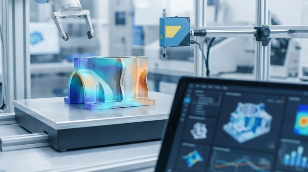
Image: 3D printed structures, showcasing the potential complexity and scale where distortion management is critical. Source: Wikimedia Commons.
Understanding Additive Manufacturing Distortion
Distortion in additive manufacturing refers to any deviation from the intended geometry of a printed part. This can manifest as warping, curling, bending, or residual stress leading to cracks. It’s a complex phenomenon primarily driven by thermal effects.
What is AM Distortion?
At its core, AM distortion is the result of internal stresses developing within the material. As material is deposited layer by layer and then cooled, different regions of the part experience varying thermal histories. This non-uniform cooling and solidification lead to differential contraction, which, when constrained, generates residual stresses that cause the part to deform.
Causes of Distortion in AM
Several factors contribute to the generation of distortion, making it a multi-faceted challenge:
- Thermal Gradients and Residual Stresses: This is the primary culprit. In processes like Laser Powder Bed Fusion (LPBF) or Electron Beam Melting (EBM), localized melting and rapid solidification create steep temperature gradients. As molten material cools and shrinks, it’s constrained by cooler, already solidified layers and the build plate, inducing tensile residual stresses.
- Phase Transformations: Some materials undergo phase changes (e.g., martensitic transformation in certain steels) during cooling, accompanied by volumetric changes. If these transformations occur non-uniformly across the part, they can exacerbate distortion.
- Part Geometry and Support Structures: Thin walls, large flat areas, overhanging features, and sharp corners are particularly prone to distortion. Inadequate or poorly designed support structures fail to provide sufficient constraint, allowing the part to warp or lift from the build plate.
- Material Properties: A material’s coefficient of thermal expansion (CTE), yield strength, elastic modulus, and thermal conductivity significantly influence its susceptibility to distortion. High CTE materials, for instance, will experience greater volumetric changes with temperature fluctuations.
- Process Parameters: Parameters like laser power, scan speed, layer thickness, hatch spacing, pre-heat temperature, and build plate temperature all affect the thermal history and energy density input, directly impacting distortion. Incorrect parameters can lead to excessive heat accumulation or insufficient fusion.
Impact of Distortion on Structural Integrity and Performance
The consequences of AM distortion extend far beyond cosmetic imperfections, directly affecting a component’s fitness for purpose, especially in high-stakes engineering applications.
Dimensional Inaccuracy
Distorted parts rarely meet the strict dimensional tolerances required by design specifications. This can lead to difficulties in assembly, fitment issues with mating components, or even outright rejection of the part, necessitating costly post-processing or complete re-fabrication.
Reduced Mechanical Properties
High residual stresses, the underlying cause of distortion, can significantly reduce a part’s mechanical performance. They can lower fatigue life, decrease fracture toughness, and make the part more susceptible to stress corrosion cracking. For critical components in aerospace (e.g., turbine blades) or oil & gas (e.g., downhole tools), this is a major concern for structural integrity.
Increased Post-Processing
Correcting distortion often requires extensive post-processing steps such as machining, grinding, or hot isostatic pressing (HIP). These operations add significant cost, time, and complexity to the manufacturing workflow, negating some of the advantages of AM. In severe cases, parts may be beyond salvage.
Component Failure
In extreme cases, high residual stresses can lead to cracking during the build process itself or premature failure during service. This is particularly critical in applications where failure could have catastrophic consequences, such as in biomechanics (implants) or structural engineering components.
Predicting and Mitigating Distortion: The Engineering Approach
A multi-pronged strategy involving design optimization, process control, and advanced simulation is essential to effectively manage and minimize AM distortion.
Pre-Processing Strategies
Design for Additive Manufacturing (DfAM)
- Optimal Part Orientation: Carefully orienting the part on the build plate can significantly reduce the need for support structures, minimize build height, and balance thermal gradients. The goal is to minimize unsupported overhangs and ensure symmetric cooling where possible.
- Support Structure Design: Supports aren’t just for structural integrity during the build; they act as heat sinks and provide critical constraint against warping. Their density, geometry, and placement must be carefully chosen. Too few, and the part distorts; too many, and post-processing becomes arduous.
- Topology Optimization: Leveraging tools like Abaqus or ANSYS Mechanical for topology optimization can lead to lightweight, high-performance designs that are also inherently less prone to distortion due to optimized material distribution and reduced stress concentrations.
- Warp Compensation: Deliberately distorting the CAD model in the opposite direction of predicted distortion (based on simulation or empirical data) can help achieve the desired final geometry. This is an advanced technique often requiring iterative refinement.
Material Selection
Choosing materials with lower coefficients of thermal expansion, higher thermal conductivity, and appropriate phase transformation characteristics can inherently reduce distortion tendencies. Understanding the material’s behavior under rapid heating and cooling cycles is key.
Process Parameter Optimization
Careful calibration of process parameters (laser power, scan speed, pre-heat temperature, etc.) is crucial. For example, higher pre-heat temperatures can reduce thermal gradients but might affect material microstructure. Simulation and design of experiments (DOE) are invaluable here.
In-Situ Monitoring and Control
Advanced AM systems are incorporating in-situ monitoring technologies (e.g., thermal cameras, melt pool sensors) to detect and potentially correct distortion in real-time. Feedback loops can adjust process parameters dynamically, though this field is still evolving.
Post-Processing Techniques
- Stress Relief (Heat Treatment): Annealing or other heat treatment processes can reduce residual stresses accumulated during the build, thereby mitigating distortion and improving mechanical properties. The specific heat treatment cycle (temperature, soak time, cooling rate) must be tailored to the material.
- Machining: For parts with tight tolerances, machining is often required after AM. This removes distorted layers and achieves the final precise dimensions.
Summary of Distortion Mitigation Strategies
Here’s a quick overview of common strategies to manage AM distortion:
| Strategy | Description | Key Benefits | Potential Drawbacks |
|---|---|---|---|
| DfAM (Orientation) | Optimizing part angle relative to build plate to minimize overhangs and supports. | Reduced support material, balanced thermal gradients, improved surface finish. | Can increase build time/height, requires careful analysis. |
| Support Structures | Adding temporary structures to anchor overhangs and dissipate heat. | Prevents collapse, manages heat, constrains warping. | Requires post-processing removal, material waste, potential surface finish issues. |
| Pre-heating/Post-heating | Controlled thermal cycles during and after the build process. | Reduces thermal gradients, minimizes residual stress. | Increases energy consumption, cycle time, can affect material microstructure. |
| Process Optimization | Adjusting laser power, scan speed, layer thickness, etc. | Fine-tunes thermal input, minimizes localized heating. | Requires extensive experimentation/simulation, complex interdependencies. |
| Warp Compensation | Pre-deforming the CAD model in the opposite direction of predicted distortion. | Achieves desired final geometry with minimal post-machining. | Requires accurate distortion prediction, iterative process. |
Simulating Additive Manufacturing Distortion: A Practical Workflow
Computational tools offer a powerful, cost-effective way to predict and mitigate distortion, allowing engineers to iterate designs and process parameters virtually before committing to expensive physical builds. This is a core aspect of modern CAD-CAE workflows.
Why Simulate?
Simulation provides a predictive capability, allowing engineers to:
- Identify distortion-prone areas early in the design phase.
- Optimize part orientation and support structure design.
- Evaluate the impact of different material properties and process parameters.
- Reduce trial-and-error experimentation, saving time and material costs.
- Quantify residual stresses and predict component performance and structural integrity.
Practical Workflow for Distortion Analysis
Simulating AM processes is computationally intensive due to the complex thermo-mechanical coupling. Here’s a typical workflow:
1. Model Setup (CAD/CAE)
- Geometry Import: Begin by importing your CAD model (e.g., from CATIA) into a pre-processor like Abaqus/CAE, ANSYS Mechanical, or MSC Patran. Simplify the geometry if necessary for computational efficiency, but retain critical features.
- Material Definition: Define temperature-dependent material properties, including thermal conductivity, specific heat, density, coefficient of thermal expansion, Young’s modulus, and yield strength. Material models should capture plasticity and potentially creep if relevant.
2. Meshing Considerations
- Element Types: Use appropriate elements for thermo-mechanical analysis (e.g., coupled temperature-displacement elements).
- Mesh Refinement: Refine the mesh in critical areas prone to high gradients (e.g., melt pool region, sharp corners, support interfaces) and coarser elsewhere to balance accuracy and computational cost. Adaptive meshing techniques can be highly beneficial.
3. Defining Process Parameters
- Heat Source Modeling: Accurately represent the moving heat source (laser or electron beam) using appropriate models (e.g., Goldak double-ellipsoid model for powder bed fusion).
- Layer Deposition: Implement element activation/deactivation techniques to simulate the layer-by-layer build process, reflecting material addition.
4. Thermal-Structural Coupling
This is the core of AM distortion simulation:
- Sequential Coupling: Often, a two-step approach is used. First, a transient thermal analysis calculates temperature distributions over time. Then, these temperature results are mapped as thermal loads onto a subsequent structural analysis to compute deformations and stresses. Tools like Abaqus and ANSYS Mechanical excel at this. For complex fluid dynamics in the melt pool (though less common for bulk distortion), CFD tools like ANSYS Fluent or OpenFOAM might be used for initial thermal input characterization.
- Fully Coupled Analysis: In some cases, a fully coupled thermo-mechanical analysis is performed where thermal and mechanical fields are solved simultaneously. This is more accurate but significantly more computationally expensive, often requiring high-performance computing (HPC) resources.
5. Boundary Conditions and Constraints
- Build Plate Interaction: Model the interaction between the part and the build plate, often through fixed displacement boundary conditions or contact elements, depending on the desired fidelity of adhesion and release.
- Support Structures: Explicitly model support structures with appropriate material properties and connections to the part and build plate to capture their constraining effect.
- Cooling Environment: Define convection and radiation boundary conditions to represent heat transfer to the surrounding inert gas atmosphere.
6. Post-Processing and Interpretation
- Displacement and Distortion: Visualize and quantify total deformation, focusing on areas with significant warpage or lifting.
- Residual Stresses: Analyze residual stress distributions, identifying high-stress regions that could lead to cracking or reduce fatigue life.
- Data Extraction and Automation: Utilize scripting languages like Python (e.g., with Abaqus scripting or pre/post-processing libraries) or MATLAB for automated data extraction, plotting, and parametric studies to quickly evaluate different design iterations.
Verification & Sanity Checks in AM Simulation
Ensuring the reliability of your simulation results is critical. These checks help build confidence in your predictions:
Mesh Sensitivity Studies
Run simulations with progressively finer meshes. Your results (e.g., max displacement, max stress) should converge to a stable value as the mesh is refined. If not, your mesh might be too coarse in critical regions.
Boundary Condition Review
Carefully re-examine all applied boundary conditions (BCs). Are the supports correctly modeled? Is the build plate constraint realistic? Are thermal BCs (convection, radiation) accurately representing the environment?
Convergence Criteria
Ensure that your solver has achieved convergence within acceptable tolerances for both thermal and mechanical solutions. Non-convergence indicates numerical instability or an ill-posed problem.
Material Model Validation
Compare the material properties used in the simulation against experimental data. Even small inaccuracies in temperature-dependent properties can significantly alter distortion predictions.
Sensitivity Analysis
Perform parametric studies to understand how variations in key input parameters (e.g., laser power, scan speed, pre-heat temperature, support density) affect distortion. This helps identify the most influential factors and guides process optimization. Tools like Python or MATLAB can automate these studies.
For engineers seeking to run complex FEA/CFD models for AM distortion or other structural integrity analyses, EngineeringDownloads offers affordable HPC rental solutions, along with specialized online/live courses, internship-style training, and project/contract consultancy to enhance your simulation capabilities.
Common Mistakes and Troubleshooting Distortion Issues
Even with careful planning, distortion can occur. Knowing common pitfalls and troubleshooting steps can save significant time and resources.
Ignoring Support Structures
A frequent error is underestimating the role of supports. They are not just for preventing collapse but are vital for heat extraction and constraining deformation. Inadequate support leads to warpage, delamination, and even complete print failure.
Inadequate Stress Relief
Skipping or improperly executing post-build stress relief (heat treatment) can leave significant residual stresses, causing parts to distort later or fail prematurely. Ensure the heat treatment protocol is optimized for your material and geometry.
Poor Material Characterization
Using generic or room-temperature material properties for simulation is a major mistake. AM involves extreme temperatures, so temperature-dependent properties are crucial for accurate predictions. Work with your material supplier or conduct experiments to get reliable data.
Overlooking Process Parameter Influence
A ‘set-and-forget’ approach to process parameters is risky. Small adjustments to laser power, scan speed, or build plate temperature can dramatically alter the thermal profile and thus distortion. Utilize DOEs and simulation to find optimal settings.
Troubleshooting Checklist
- Review Geometry and Orientation: Are there thin sections, large unsupported overhangs, or flat areas that are known to warp? Can the part be re-oriented?
- Inspect Support Structures: Are supports sufficient in density and placement, especially under critical features? Are they strong enough to resist warping forces?
- Check Build Plate Adhesion: Is the part properly adhered to the build plate? Lifting corners are a clear sign of distortion. Consider build plate temperature, surface preparation, or adhesive.
- Verify Process Parameters: Are laser power, scan speed, and layer thickness within recommended ranges for your material? Is the pre-heat temperature appropriate?
- Monitor Build Environment: Are chamber temperature and inert gas flow consistent? Drafts or temperature fluctuations can induce localized cooling and stress.
- Evaluate Post-Processing: Was stress relief performed correctly? Could the part have distorted during removal from the build plate or subsequent handling?
Case Studies & Industry Applications (Illustrative Examples)
Understanding distortion is critical across diverse engineering sectors:
- Aerospace Components: For parts like turbine blades or structural brackets, dimensional accuracy is paramount for assembly and aerodynamic performance. Residual stresses can severely impact fatigue life, a critical factor for aircraft safety. Simulation helps predict these effects in materials like Inconel or Ti-6Al-4V.
- Medical Implants (Biomechanics): Orthopedic or dental implants require precise fit and long-term structural integrity. Distortion can lead to poor osseointegration or premature failure. Understanding the distortion of biocompatible materials like Ti-6Al-4V or Cobalt-Chrome is vital.
- Oil & Gas Industry: Components for downhole tools or complex nozzles often operate in harsh environments. AM offers unique design freedom for these parts. Distortion in superalloys or high-strength steels can compromise sealing, flow paths (CFD considerations), or structural reliability under extreme pressures and temperatures.
Key Takeaways for Engineers
Addressing additive manufacturing distortion requires a holistic approach:
- Embrace DfAM: Design parts specifically for AM, considering orientation, geometry, and support structures from the outset.
- Leverage Simulation: Utilize FEA tools like Abaqus and ANSYS Mechanical for thermo-mechanical simulation to predict and mitigate distortion virtually.
- Optimize Process Parameters: Understand the interplay between laser power, scan speed, and temperature on thermal gradients.
- Don’t Skip Post-Processing: Stress relief is often non-negotiable for critical components to improve structural integrity.
- Continuous Learning: AM is rapidly evolving. Stay updated on new materials, processes, and simulation techniques.
By integrating these practices, engineers can unlock the full potential of additive manufacturing, producing high-quality, distortion-free components for even the most demanding applications.
Further Reading
For more in-depth technical details on modeling additive manufacturing processes, refer to reputable software documentation and research papers:
Dassault Systèmes SIMULIA Abaqus Additive Manufacturing Solutions


