

Additive Manufacturing (AM), commonly known as 3D printing, has revolutionized product development across industries from aerospace to biomedical. Its ability to create complex geometries and functional prototypes quickly is unmatched. However, like any advanced manufacturing process, AM comes with its unique set of challenges. One of the most persistent and critical issues facing engineers is additive manufacturing distortion.
Distortion refers to the unintended deformation or change in shape of a 3D printed part, primarily caused by residual stresses built up during the printing and cooling phases. This phenomenon can lead to significant dimensional inaccuracies, compromised mechanical properties, and ultimately, part failure. Understanding, predicting, and mitigating distortion is paramount for successful AM adoption and producing high-quality, reliable components.

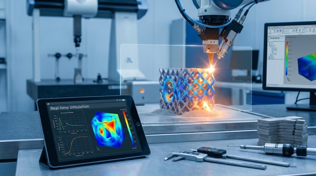
Warpage due to unsupported overhang in additive manufacturing. (Source: Wikimedia Commons, CC BY-SA 4.0)
Understanding the Root Causes of Additive Manufacturing Distortion
Distortion in AM is a complex interplay of thermal, mechanical, and material factors. Pinpointing the exact cause often requires a systematic approach, but several primary drivers are consistently observed:
Thermal Stresses: The Primary Culprit
The layer-by-layer nature of most AM processes, especially powder bed fusion (PBF) techniques like Selective Laser Sintering (SLS) or Selective Laser Melting (SLM), involves rapid heating and cooling cycles. As new material layers are added and solidified, they experience significant temperature gradients. When a hot layer cools and contracts on top of an already solidified, cooler layer, it induces tensile stresses. These stresses accumulate throughout the build, and if they exceed the material’s yield strength, plastic deformation – or distortion – occurs.
- Temperature Gradients: Large differences between the melt pool and the surrounding material or build plate.
- Cooling Rates: Faster cooling generally leads to higher residual stresses.
- Material Properties: Thermal expansion coefficient, thermal conductivity, and specific heat play crucial roles.
Residual Stresses: A Lingering Problem
Even after a part has cooled to room temperature, the internal stresses don’t simply disappear. These trapped internal forces are known as residual stresses. While some residual stress can be beneficial (e.g., compressive stress on surfaces), tensile residual stresses are detrimental, often leading to:
- Reduced fatigue life.
- Lower fracture toughness.
- Increased susceptibility to stress corrosion cracking.
- Significant warping or bending once the part is removed from the build plate or support structures are removed.
Part Geometry and Support Structures
The design of the part itself and the way it’s supported during the build process are major contributors to distortion:
- Overhangs and Cantilevers: Unsupported or inadequately supported features are highly prone to warping or curling due to uneven heat dissipation and thermal contraction.
- Thin Walls and Large Flat Areas: These geometries are particularly susceptible to buckling and warpage as they have less inherent stiffness to resist thermal stresses.
- Support Structure Design: The density, geometry, and placement of support structures affect heat transfer, part removal ease, and crucially, how well they resist part deformation during the build. Insufficient supports can lead to catastrophic distortion.
Material Properties
Different materials behave differently under thermal cycling. Materials with a high coefficient of thermal expansion, low thermal conductivity, and high yield strength at elevated temperatures are generally more prone to distortion. Common AM materials like titanium alloys, nickel-based superalloys, and certain high-performance polymers often present significant distortion challenges due to these inherent properties.
Process Parameters
Every AM process has a myriad of parameters that directly influence the thermal history and stress development:
- Laser Power/Scan Speed: Directly impacts the energy input and melt pool dynamics.
- Layer Thickness: Affects thermal gradients and the number of thermal cycles.
- Build Plate Temperature: Elevating the build plate or chamber temperature can reduce the temperature gradient between the new layer and existing part, thereby reducing stress.
- Scan Strategy: Patterns like zigzag, island scanning, or meander can influence the distribution of residual stress.
Types of Distortion in Additive Manufacturing
Distortion can manifest in various forms, each with distinct characteristics and challenges:
-
Warpage (Bending/Curling)
This is the most common type, where flat sections of a part bend or curl upwards from the build plate or from their intended plane. It’s often seen in large, flat geometries or unsupported overhangs, driven by accumulated residual stresses.
-
Shrinkage
Overall reduction in part dimensions compared to the CAD model. While predictable to some extent through scaling factors, non-uniform shrinkage can still lead to dimensional inaccuracies and internal stresses.
-
Delamination
Separation between layers or from the build plate. This is a severe form of distortion, often resulting from excessively high tensile residual stresses that overcome the interlayer bonding strength.
-
Thermal Cracking
For brittle materials or those with poor ductility at higher temperatures, accumulated tensile stresses can lead to actual cracking, especially at sharp corners or stress concentrators.
The Impact of Distortion on Engineering Applications
The consequences of unchecked distortion can be severe, impacting various engineering domains:
| Impact Area | Description | Relevance to Engineering Downloads Fields |
|---|---|---|
| Dimensional Inaccuracy | Part dimensions deviate significantly from the CAD model, failing to meet tight tolerances required for assembly or function. | Structural Engineering, Aerospace (fit-up), Biomechanics (implant fit) |
| Compromised Mechanical Properties | High residual tensile stresses reduce fatigue life, fracture toughness, and overall structural integrity, potentially leading to premature failure. | Structural Integrity, FFS Level 3, Oil & Gas (critical components) |
| Increased Post-Processing & Cost | Distorted parts often require extensive post-machining to meet specifications, increasing cost, time, and material waste (scrap). | CAD-CAE Workflows, Manufacturing Efficiency |
| Production Delays & Failure | Failed builds lead to wasted material, machine time, and significant delays in bringing products to market or deploying critical components. | Project Management, Supply Chain Reliability |
Strategies for Mitigation: Controlling Distortion in AM
Mitigating distortion requires a holistic approach, considering every stage of the AM workflow. Here are practical strategies:
Pre-Processing Techniques: Design and Planning
The best defense against distortion starts before the build begins.
1. Part Design Optimization
- Design for Additive Manufacturing (DfAM): Engineers should design parts with AM process limitations in mind. Avoid large unsupported overhangs, sharp corners, and excessively thin walls where possible.
- Topology Optimization: Use tools to optimize material distribution, reducing mass while maintaining structural performance. This can lead to more uniform thermal distribution and reduced stress concentration points.
- Lattice Structures: Incorporating lattice infills can reduce overall material usage, potentially lowering thermal mass and reducing distortion, especially in large volumes.
2. Support Structure Optimization
- Strategic Placement: Place supports under critical overhangs and features prone to curling.
- Density and Type: Adjust support density based on part geometry and material. Dense supports provide better thermal conduction and mechanical restraint, but are harder to remove. Consider different support types (e.g., lattice, block, point) for specific needs.
- Connect to Build Plate: Ensure robust connection of supports to the build plate to anchor the part effectively.
3. Build Orientation
- Orient the part to minimize unsupported areas, especially critical surfaces.
- Reduce the part’s cross-sectional area per layer to minimize thermal input at any given moment, though this increases build time.
- Consider minimizing the Z-height for parts prone to Z-direction cracking or delamination.
4. Material Selection
- Where design allows, select materials less prone to thermal distortion. For example, some polymers exhibit lower thermal expansion coefficients than others.
- Ensure material properties are well-characterized for the specific AM process.
5. Pre-Compensation (Warping)
- Based on simulation or empirical data, intentionally deform the CAD model in the opposite direction of expected distortion. The part then distorts back into the desired shape during the build. This requires accurate prediction of distortion.
In-Process Control: During the Build
Optimizing machine parameters directly affects the thermal environment.
1. Process Parameter Optimization
- Energy Density: Fine-tune laser power, scan speed, hatch spacing, and layer thickness to achieve optimal melting while minimizing thermal input.
- Scan Strategy: Implement advanced scan strategies (e.g., island scanning, alternating scan directions) to distribute heat more uniformly and break up continuous stress fields.
- Build Chamber Temperature: For many metal AM processes, preheating the build plate and maintaining an elevated chamber temperature significantly reduces thermal gradients, leading to lower residual stresses and less distortion.
2. In-situ Monitoring
- Advanced AM machines can incorporate sensors for real-time temperature, melt pool size, and even stress monitoring. This data can be used for adaptive process control or early detection of distortion issues.
Post-Processing Solutions: After the Build
Once the part is off the machine, further steps can relieve residual stresses.
1. Heat Treatment (Stress Relieving)
- Controlled annealing cycles can relax internal stresses by allowing atomic rearrangement within the material. This is crucial for improving structural integrity and reducing the risk of further distortion upon removal from the build plate.
- The specific heat treatment parameters (temperature, soak time, cooling rate) are material-dependent and critical for success.
2. Machining
- If distortion is minor and within machining allowance, post-machining can correct dimensional inaccuracies. However, this adds cost and time and doesn’t eliminate underlying residual stresses.
Simulation and Predictive Modeling: A Powerful Tool (FEA/CFD Focus)
Given the complexity of thermal and mechanical interactions in AM, simulation has become indispensable for predicting and mitigating distortion. Engineers can leverage advanced computational tools to virtually test designs and process parameters before committing to expensive physical builds.
Practical Workflow for Additive Manufacturing Distortion Simulation
Finite Element Analysis (FEA) and Computational Fluid Dynamics (CFD) are key here, often coupled. A typical workflow involves:
- Geometry Preparation: Start with the CAD model (e.g., from CATIA or SolidWorks). Simplify features if necessary for meshing efficiency while retaining critical geometry.
- Material Definition: Accurately define temperature-dependent material properties: thermal conductivity, specific heat, coefficient of thermal expansion, Young’s modulus, yield strength, and Poisson’s ratio. This data is crucial for accurate thermal and mechanical response.
- Meshing: Create a finite element mesh. Fine meshes are needed in areas of high thermal or stress gradients (e.g., melt pool, sharp corners), while coarser meshes can be used elsewhere. Techniques like adaptive meshing or sub-modeling can be employed.
- Process Modeling: Simulate the AM process itself. This typically involves a transient thermal analysis to capture the moving heat source (laser/electron beam) and subsequent cooling. Tools like Abaqus, ANSYS Mechanical, and specialized AM simulation software can perform these complex thermo-mechanical analyses.
- Thermal-Mechanical Coupling: The temperature history from the thermal analysis is then applied as a load to a structural analysis to calculate thermal stresses, plastic deformation, and resulting distortion. This can be done sequentially (thermal then mechanical) or in a fully coupled manner, depending on the software and desired accuracy.
- Boundary Conditions (BCs): Define appropriate mechanical boundary conditions for the part’s connection to the build plate and support structures. Thermal BCs include convection, radiation, and initial temperatures.
- Solver Execution: Run the simulation. This can be computationally intensive, often requiring significant High-Performance Computing (HPC) resources. EngineeringDownloads offers affordable HPC rental to run such complex models efficiently.
- Post-processing and Visualization: Analyze the results using tools like Abaqus/Viewer, ANSYS Workbench, or MSC Patran/Nastran. Visualize deformation, stress contours, and identify areas prone to distortion or failure. Python and MATLAB can be invaluable for automating post-processing tasks, extracting specific data points, and creating custom plots or reports.
- Optimization: Based on simulation results, iterate on part design, support structures, build orientation, or process parameters to minimize distortion.
Verification & Sanity Checks in AM Simulation
Trusting simulation results requires rigorous verification and validation:
-
Mesh Sensitivity/Convergence Studies
Ensure that refining the mesh further does not significantly change the results. This confirms that the discretization error is acceptable.
-
Boundary Condition Validity
Are the applied boundary conditions (e.g., constraints at the build plate, heat transfer coefficients) physically realistic and representative of the actual manufacturing setup?
-
Convergence Criteria
Confirm that the numerical solver converged successfully. Non-convergence or slow convergence can indicate issues with the model setup, material properties, or excessive nonlinearity.
-
Material Model Validation
Verify that the temperature-dependent material properties used in the simulation accurately represent the AM material’s behavior under the rapid heating and cooling cycles. Comparison with experimental material characterization data is ideal.
-
Sensitivity Analysis
Investigate how changes in key input parameters (e.g., laser power, build plate temperature, material properties) affect the predicted distortion. This helps identify critical parameters and their acceptable ranges.
-
Simplified Model & Analytical Comparisons
For basic checks, compare simulation results with simplified analytical solutions (if available) or results from a highly simplified FEA model. Does the deformation direction make sense? Are stress magnitudes reasonable?
Common Mistakes and Troubleshooting Additive Manufacturing Distortion
Even with advanced tools, engineers can fall into common pitfalls:
- Ignoring Build Plate/Part Adhesion: Insufficient adhesion leads to delamination from the build plate, causing severe warpage.
- Underestimating Thermal Gradients: Not accounting for the extreme temperature differences and their impact on material properties.
- Inadequate Support Structures: Placing too few, too thin, or poorly designed supports, especially for large overhangs.
- Using Generic Material Data: Relying on standard bulk material properties instead of AM-specific, temperature-dependent data, which can differ significantly.
- Not Stress Relieving: Skipping post-build heat treatment, leaving high residual stresses that can lead to unexpected distortion or failure in service.
- Over-optimizing for Build Time: Aggressively increasing build speed or layer thickness without considering the thermal implications, often leading to increased distortion.
- Lack of Iteration: Expecting a perfect build on the first attempt without leveraging simulation or experimental feedback for design and process iteration.
Applications Across Industries
Controlling additive manufacturing distortion is critical across diverse engineering fields:
- Aerospace: High-performance components for engines and airframes require extreme dimensional accuracy and structural integrity, where distortion can lead to part rejection.
- Oil & Gas: Complex impellers, valves, and other critical parts used in harsh environments demand precise fit and freedom from residual stress to ensure reliability (relevant to FFS Level 3 assessments).
- Biomechanics: Custom medical implants (e.g., orthopedic, dental) must fit perfectly and maintain their intended shape to ensure patient safety and functional success.
Conclusion
Additive manufacturing distortion remains a significant hurdle, but it’s a challenge that can be overcome with a structured, informed approach. By understanding its root causes, employing smart design and process strategies, and leveraging powerful simulation tools like FEA, engineers can proactively predict, prevent, and mitigate distortion. Embracing a comprehensive workflow that includes iterative design, simulation-driven optimization, and proper post-processing is key to unlocking the full potential of additive manufacturing and consistently producing high-quality, high-performance components.
Further Reading
Additive Manufacturing Benchmark Test Series: Measurement and Evaluation of Distortion – NIST


