Unlocking Design Freedom: A Practical Guide to Topology Optimization
In the world of engineering design, the quest for lighter, stronger, and more efficient components is relentless. Traditional design often involves iterative guesswork or incremental improvements. But what if you could let algorithms discover the optimal material distribution within a given space? That’s precisely what Topology Optimization (TO) offers.
Topology Optimization is a powerful computational design method that determines the optimal material layout within a predefined design domain, subjected to specific loads, boundary conditions, and performance targets. Essentially, it helps engineers find the ‘best’ shape for a part by strategically removing material, leaving behind only what’s necessary to meet functional requirements.

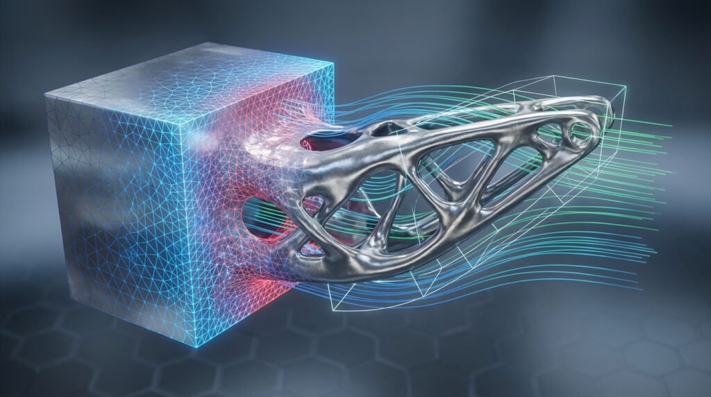
Illustrative example of topology optimization reducing material in a bracket.
This isn’t just about making things lighter; it’s about maximizing performance, reducing material waste, and often leading to innovative, organic shapes that are difficult to conceive with conventional design methods. For engineers working in structural integrity, aerospace, automotive, or even biomechanics, mastering TO can be a game-changer.
Why Topology Optimization Matters for Engineers
Topology optimization isn’t just a fancy academic concept; it delivers tangible benefits:
- Significant Weight Reduction: Critical for aerospace components, automotive parts, and any application where mass is a key constraint. Lighter parts mean better fuel efficiency, reduced inertia, and lower material costs.
- Enhanced Performance: Optimize for stiffness, natural frequency, or stress distribution, leading to more robust and reliable designs.
- Material Efficiency: Use less raw material without compromising structural integrity, contributing to sustainability efforts and cost savings.
- Innovation & Complex Geometries: Unlocks designs with organic, lattice, or highly intricate forms often ideal for additive manufacturing (3D printing).
- Accelerated Design Cycles: Automate the initial conceptual design phase, allowing engineers to explore a wider design space faster.
Whether you’re dealing with FFS Level 3 assessments in oil & gas, designing critical airframe components, or developing medical implants, TO provides a systematic approach to achieving optimal structural performance.
The Core Concept: How Topology Optimization Works
At its heart, topology optimization is an iterative process driven by a finite element analysis (FEA) solver. Here’s a simplified breakdown:
- Define the Design Domain: You start with a ‘blank canvas’ – a maximum volume of material where your component can exist. This is often an enclosing box or a rough initial design CAD model.
- Apply Loads & Boundary Conditions: Just like any FEA setup, you specify where the part is fixed, where forces are applied, and in what direction. These are crucial for the optimization process.
- Set Objective & Constraints:
- Objective: What do you want to achieve? Typically, this is minimizing compliance (maximizing stiffness) or minimizing mass.
- Constraints: What limitations must the design adhere to? Common constraints include a maximum volume fraction (e.g., reduce volume by 50%), stress limits, displacement limits, or manufacturing feasibility.
- Iterative Material Redistribution: The optimization algorithm, often based on methods like Solid Isotropic Material with Penalization (SIMP) or Evolutionary Structural Optimization (ESO), iteratively removes or adds material from elements within the design domain. Elements contributing little to the structural integrity are gradually eliminated.
- Convergence: The process continues until the objective function is minimized, and all constraints are satisfied, or until a predefined number of iterations is reached. The result is a density distribution map, where high-density areas represent where material should be, and low-density areas represent voids.
This density map is then interpreted to create a new, optimized geometry.
A Practical Topology Optimization Workflow: Step-by-Step
For engineers, integrating TO into their CAD-CAE workflows requires a systematic approach. Here’s a robust workflow:
1. Initial Design & Domain Definition (CAD)
- Identify the Design Space: Start with a CAD model of your component or the surrounding assembly. Define the maximum allowable envelope for your part.
- Define Non-Design Regions: These are areas where material must exist, typically for connections (bolt holes, mounting surfaces) or interfaces with other components. Create these as ‘keep-out’ zones in your CAD tool (e.g., CATIA, SolidWorks, PTC Creo).
- Example: For an aerospace bracket, the bolt holes connecting to the fuselage and the mounting surface for an avionics box would be non-design regions.
2. Load Cases & Boundary Conditions (FEA Pre-processing)
- Understand Real-World Conditions: Accurately capture all operating loads (static, dynamic, thermal) and boundary conditions. This is the most critical step – ‘garbage in, garbage out’ applies strongly here.
- Apply BCs: Specify fixed supports, frictionless contacts, remote forces, and pressures. Think about the worst-case scenarios and potential load combinations.
- FEA Tools: Use pre-processors in software like Abaqus/CAE, ANSYS Mechanical, or MSC Patran to set these up. Consider gravity, temperature changes, and vibration loads if applicable.
3. Mesh Generation
- Quality over Quantity: A good quality mesh is essential. For TO, a relatively fine mesh throughout the design domain is often required to capture intricate details, especially in areas where material might be removed.
- Element Type: Typically, solid (tetrahedral or hexahedral) elements are used.
- Mesh Sensitivity: Perform initial FEA runs to ensure your mesh resolution is adequate before starting the optimization.
4. Define Optimization Problem
- Objective Function: The most common is ‘Minimize Compliance’ (which equates to maximizing stiffness). Others include minimizing mass, maximizing natural frequency.
- Constraints:
- Volume Fraction: E.g., ‘Target a volume reduction of 60%’.
- Stress Constraints: Ensure maximum stress doesn’t exceed yield strength.
- Displacement Constraints: Limit deformation in specific areas.
- Manufacturing Constraints: Very important! Specify minimum member size, draw directions, symmetry, or demolding requirements. This ensures manufacturability, especially for traditional processes.
- Optimization Parameters: Select the algorithm (e.g., SIMP), penalization parameters, and convergence criteria.
5. Run Optimization (Solver)
- The solver (e.g., Abaqus, ANSYS DesignXplorer, Altair OptiStruct) iteratively performs FEA, calculates sensitivities, updates material densities, and removes elements.
- Monitor the convergence plot – the objective function should stabilize.
6. Post-processing & Geometry Reconstruction
- Interpret Density Plot: The output is a density field. Thresholding is often used to define the boundary between solid and void.
- Smoothening & Remeshing: The raw topology optimized shape often has jagged edges. Use meshing tools or specialized algorithms to smooth the surface and create a watertight CAD model (e.g., using reverse engineering tools, polygon editing, or built-in functions in CAD/CAE software).
- Convert to CAD: Export the smoothed mesh as an STL file, then use CAD software (like CATIA or design-focused modules in Abaqus/ANSYS) to convert it into a solid body for further refinement and detailed design.
7. Validation (FEA Re-analysis)
- Once you have a new CAD model, perform a full FEA analysis on this geometry with the original loads and boundary conditions.
- Crucial Step: Verify that the optimized design meets all performance targets (stress, displacement, natural frequency) and safety factors.
Practical Tips for Successful Topology Optimization
Getting useful results from TO often involves more than just clicking ‘run’.
- Start Simple: Begin with a simplified model or fewer load cases to understand the behavior before adding complexity.
- Realistic Boundary Conditions: Spend significant time ensuring your BCs accurately represent the real-world application. Incorrect BCs will lead to flawed designs.
- Consider Manufacturing: Always apply manufacturing constraints early in the process. Without them, you’ll often get complex, organic shapes that are impossible to produce with traditional methods like machining or molding. Additive manufacturing (3D printing) offers more freedom but still has limitations (overhangs, minimum feature size).
- Multiple Load Cases: Most real-world components experience various loads. Incorporate all critical load cases into your optimization. The algorithm will then find a design that performs well under all specified conditions.
- Mesh Refinement Studies: Perform several runs with different mesh densities, especially in the design domain, to ensure your results are mesh-independent.
- Parameter Sensitivity: Experiment with different volume fractions or penalization parameters to understand how they affect the final shape.
- Post-processing is Key: The raw output is rarely production-ready. Invest time in smoothing, reconstruction, and ensuring the final CAD is robust.
Common Mistakes to Avoid
Even experienced engineers can stumble. Watch out for these pitfalls:
- Ignoring Manufacturing Constraints: This is arguably the biggest mistake. A perfectly optimized shape that can’t be made is useless.
- Over-simplifying Loads/BCs: Missing critical load cases or inaccurately applying boundary conditions will lead to an underperforming or failing part.
- Poor Mesh Quality: Coarse meshes miss details; highly distorted elements lead to inaccurate stress predictions.
- Not Validating Results: Never assume the optimized shape is correct without a separate FEA validation.
- Expecting a ‘Final’ CAD from TO: TO provides a conceptual design. It needs engineering interpretation, clean-up, and often some manual refinement.
- Running Too Many Iterations: While important, excessive iterations might lead to diminishing returns or numerical issues without improving the design significantly.
Verification & Sanity Checks
After the optimization run, a rigorous verification process is non-negotiable for structural integrity and FFS Level 3 applications.
- FEA Re-analysis: This is paramount. Run a new static or dynamic FEA on the *reconstructed* and *smoothed* CAD model using the original loads and BCs. Compare stresses, displacements, and natural frequencies against your design criteria.
- Sensitivity Analysis: How does the design perform if loads or material properties vary slightly? This helps assess robustness.
- Convergence Plot Review: Did the objective function and constraints stabilize? Erratic convergence might indicate numerical issues or an ill-posed problem.
- Compare with Traditional Designs: If possible, compare the optimized design’s performance metrics (e.g., stiffness-to-weight ratio) against a traditionally designed component. This provides a baseline.
- Physical Intuition: Does the shape make sense? While TO creates organic forms, the load paths should still appear logical and efficient from an engineering perspective.
- Displacement and Stress Contours: Visually inspect these plots on the optimized design. Are there any unexpected hot spots or areas of excessive deformation?
Software Tools for Topology Optimization
A range of powerful software solutions facilitate topology optimization:
- Abaqus/Topology Optimization Module: Integrated within the Abaqus/CAE environment, it offers robust capabilities for structural optimization, including stress, displacement, and frequency response objectives. Excellent for complex non-linear problems.
- ANSYS Mechanical (DesignXplorer): ANSYS offers topology optimization within its Workbench environment. It’s user-friendly and integrates well with other ANSYS modules like structural analysis and explicit dynamics.
- Altair OptiStruct: A standalone, industry-leading optimization solver known for its advanced capabilities in topology, size, shape, and free-shape optimization, used widely in aerospace and automotive.
- MSC Nastran & Patran: MSC Nastran provides optimization capabilities, and Patran serves as the pre/post-processor, offering comprehensive structural analysis and optimization.
- CATIA Generative Design: Integrated into the CATIA platform, it provides design tools for creating generative shapes, including topology optimization, complementing its powerful CAD features.
- Python & MATLAB: For advanced users and researchers, scripting with libraries like NumPy, SciPy, and specialized topology optimization libraries (e.g., TopOpt for Python) allows for custom algorithms and integration into broader automation scripts. These are particularly useful for academic research or integrating TO into existing proprietary simulation frameworks. EngineeringDownloads.com often features downloadable Python and MATLAB scripts for FEA post-processing and parametric studies that can complement TO workflows.
Advanced Considerations in Topology Optimization
As you become more proficient, you’ll encounter more advanced scenarios:
- Multi-objective Optimization: Balancing conflicting objectives, such as minimizing mass while also maximizing the first natural frequency.
- Fatigue and Durability: Incorporating fatigue life as a constraint or objective. This is critical for components subjected to cyclic loading.
- Buckling Constraints: Preventing buckling instability in slender structures.
- Multi-Physics Optimization: While primarily structural, TO can be extended. For example, optimizing heat sink geometry for thermal performance or designing fluidic channels for minimal pressure drop (closer to CFD, potentially using algorithms inspired by TO).
- Variable Density Materials: Exploring how material density can vary across the design space, moving beyond simple ‘material or no material’.
Need hands-on help with implementing topology optimization, setting up complex load cases, or developing custom Python scripts for your FEA post-processing? Explore EngineeringDownloads.com for project templates, insightful tutorials, or expert consultancy services that can guide you through these advanced topics.
Conclusion
Topology optimization is more than just a tool for lightweighting; it’s a paradigm shift in engineering design. By leveraging computational power, engineers can discover innovative, high-performance, and material-efficient designs that were previously unattainable. While it demands careful setup, validation, and an understanding of manufacturing constraints, the benefits in terms of performance, cost, and sustainability are immense. Embrace TO to push the boundaries of what’s possible in your structural engineering and design projects.
Further Reading
For more in-depth technical documentation on topology optimization methods and their application in commercial software, refer to the official Altair OptiStruct documentation: Altair OptiStruct Official Website