Introduction
Structural optimization is an established engineering methodology used to improve structural designs by systematically changing material distribution, geometry, or member sizing to meet defined performance targets. In most engineering organizations, optimization is no longer “nice to have.” It is a practical way to reduce mass, improve stiffness, control stress hotspots, and increase overall efficiency especially when weight, cost, or sustainability metrics matter.
This guide is written for engineers who already work with FEA workflows and want a structured, tool-oriented view of structural optimization. The focus is on common industrial platforms such as ANSYS, Abaqus, and COMSOL, including typical automation paths (scripting and solver coupling). A downloadable worked example is also included: Topology Optimization of a Jet Engine Bracket with a validated simulation workflow.
Safety disclaimer (engineering responsibility): Optimization outputs are not “final designs.” Always validate the optimized geometry with an independent, high-fidelity analysis (fine mesh, all load cases, correct contacts, realistic boundary conditions). Check compliance with applicable standards and safety factors using qualified engineering judgment. Use this content for educational and engineering guidance only do not deploy an optimized result without verification, review, and (where required) certification processes.
Key Takeaways
-
Structural optimization is an iterative design process that uses computational analysis (typically FEA) to improve a structure toward an objective while meeting constraints.
-
The main categories are topology optimization, shape optimization, and size optimization, each changing a different part of the design definition.
-
Modern CAE tools (e.g., ANSYS, Abaqus, COMSOL) provide optimization capabilities and often support scripting integration for automation and custom workflows.
-
Optimization can deliver lighter and stronger designs by removing inefficient material and improving load paths, rather than relying on manual trial-and-error.
-
Always validate results with a separate verification analysis and engineering checks; optimization is an accelerator, not a substitute for design responsibility.
What Is Structural Optimization?
Structural optimization is an iterative engineering design process that improves a structure by adjusting material distribution, shape, or size to reach specific objectives (for example, minimize mass, maximize stiffness, or minimize stress) while satisfying constraints (for example, stress allowable, displacement limit, frequency target, buckling margin, or manufacturing rules).
In practical terms, the workflow usually looks like this: you define what “good” means (the objective), what must not be violated (constraints), and what the optimizer is allowed to change (design variables). The system then runs repeated analyses—most commonly Finite Element Analysis (FEA)—to evaluate many design variants. Based on each analysis result, the optimizer updates the design and repeats the loop until convergence or acceptable performance is achieved.
Structural optimization is not one single technique. It is an umbrella term that includes several optimization modes such as:
-
Topology optimization (material layout and load path discovery)
-
Shape optimization (boundary refinement and geometry tuning)
-
Size optimization (thicknesses, cross-sections, and member sizing)
These methods are widely used in aerospace, automotive, civil engineering, and industrial machinery design because they produce efficient structures with better performance-to-weight ratios than intuition-only iterations.
Why Use Structural Optimization in Design?
Structural optimization is used because it delivers measurable benefits in mass, performance, cost, and sometimes even design creativity:
1) Significant weight reduction with controlled performance
A key motivation is mass reduction. Reducing mass lowers raw material cost and can reduce operational cost (for example, fuel consumption in transportation systems). Optimization often achieves this by identifying and removing material from regions that contribute little to stiffness or strength under the specified load cases.
2) Improved structural performance and load path efficiency
Even when weight is not the only target, optimized structures often show:
-
Improved stress distribution
-
Reduced peak stresses (after proper interpretation and redesign)
-
Better stiffness-to-weight ratio
-
Clearer load paths (material placed where loads flow)
When done properly, optimized designs can maintain or even improve structural performance while using less material—hence the common description: “lighter and stronger.”
3) Systematic process that outperforms trial-and-error
Optimization is not guesswork. Instead of a designer manually removing material and checking results repeatedly, the algorithm evaluates the structure systematically. Many optimizers focus on removing “inefficient” material, which often correlates with low contribution to strain energy or stiffness. In effect, the solver tells you where material is not carrying meaningful load.
4) Innovation and concept generation beyond intuition
Especially with topology optimization, results can be non-intuitive. The algorithm can propose structural forms that an engineer might not sketch immediately (for example, truss-like ribs, branching struts, organic-looking webs). This makes optimization useful not only for final weight reduction, but also as a design idea generator early in development.
5) Sustainability and material efficiency
Using less material can reduce embodied carbon and waste. Even when sustainability is not the primary target, optimization aligns naturally with material efficiency objectives and can support lower CO₂ footprint strategies by reducing mass and processing requirements.
What Are the Types of Structural Optimization?
In structural engineering practice, three main types are used most frequently. They differ mainly by what the optimizer is allowed to change.
1) Size optimization
Size optimization adjusts member dimensions in a predefined layout. The topology (connectivity) stays the same, but sizes change, such as:
-
Plate thickness
-
Beam cross-sectional area
-
Shell thickness distribution
-
Stiffener dimensions
This is often the most straightforward type because it typically uses a small number of parameters and integrates well with existing CAD/CAE workflows.
2) Shape optimization
Shape optimization modifies the geometry boundary while keeping the overall connectivity and topology fixed. Typical changes include:
-
Fillet radii
-
Profile curvature
-
Hole shape and location (within allowed limits)
-
External surface movement of selected boundaries
Shape optimization is frequently used to reduce stress concentration and improve stiffness with minimal manufacturing disruption.
3) Topology optimization
Topology optimization determines where material should exist inside a defined design space. It can introduce holes, remove large volumes, and create new internal load paths. A common setup is:
-
Start with a solid “design space” volume
-
Define non-design regions (for example, bolt holes, interfaces, keep-out zones)
-
Set objective (often minimize compliance / maximize stiffness for a given mass)
-
Apply a volume fraction constraint or mass target
-
Run iterative removal/redistribution of material
Topology optimization often produces organic or lattice-like concepts. These can be excellent for additive manufacturing or as concept-level guidance for conventional manufacturing.
Additional categories (optional but relevant)
Depending on software and industry, you may also see:
-
Topography optimization (bead patterns for shells)
-
Free-size optimization (thickness distribution without predefined sizing regions)
-
Lattice optimization (internal lattice parameters for 3D printing)
Shared concept across all types
All types follow the same optimization structure:
-
Objective function
-
Constraints
-
Design variables
-
Iterative solution driven by repeated FEA
Because optimization requires many analyses, software automation and scripting are common, especially in industrial-scale problems with multiple load cases and verification steps.
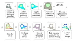
How to Perform Structural Optimization (Step-by-Step Guide)
Below is a generic workflow that applies to most optimization tools, including ANSYS, Abaqus-based workflows, and COMSOL. The user interface differs, but the engineering logic is the same.
1) Define Objectives
Decide what performance metric should be improved. Common objectives include:
-
Minimize mass (often used as a proxy for cost or efficiency)
-
Maximize stiffness (often implemented as minimize compliance)
-
Minimize peak stress (used carefully; can be sensitive to mesh and local effects)
-
Maximize natural frequency / meet vibration targets
-
Minimize deformation under service load
The objective becomes the mathematical target the optimizer tries to improve.
2) Set Constraints
Constraints define what the design must satisfy. Typical constraint categories:
-
Stress constraints (stress below allowable / yield limit with safety factor)
-
Displacement constraints (serviceability and functional clearances)
-
Frequency constraints (avoid resonance)
-
Buckling constraints (global and local stability requirements)
-
Manufacturing constraints (symmetry, minimum thickness, draw direction, extrusion constraints, overhang limits for additive manufacturing)
-
Geometric constraints (preserve bolt-hole locations, interfaces, keep-out regions)
A clear example requirement statement is:
“Reduce mass by 30% while keeping maximum stress under allowable, maintaining bolt-hole regions and interface geometry.”
Constraints are where engineering reality enters. If constraints are incomplete or wrong, the optimization can be mathematically successful but physically useless.
3) Choose Design Variables
Design variables define what can change:
-
For size optimization: thickness parameters, cross-sectional areas, stiffener sizes
-
For shape optimization: node coordinates, boundary control points, geometry parameters
-
For topology optimization: element density variables (often continuous 0–1 in SIMP-type approaches)
This step also includes defining the design space:
-
Regions allowed to change (design domain)
-
Regions that must not change (non-design domain)
-
Additional restrictions (symmetry planes, keep-out volumes)
4) Select an Optimization Method
Many CAE tools hide algorithm selection behind settings, but conceptually you are choosing an approach:
-
Gradient-based methods (efficient for smooth, continuous variables; common in size/shape problems)
-
Evolutionary / genetic algorithms (robust for discrete/nonlinear search but computationally expensive)
-
Topology optimization methods such as SIMP (density-based) or level-set approaches
The “best” method depends on the design variable type, nonlinearities, contact behavior, and how expensive the analyses are.
5) Run the Optimization Iterations
The loop typically looks like:
-
Solve FEA
-
Evaluate objective and constraints
-
Update design variables
-
Repeat until convergence
Optimization can require dozens to hundreds of iterations, especially for topology optimization with fine meshes. During runs, monitor:
-
Objective trend (is it improving smoothly?)
-
Constraint satisfaction (are constraints violated or unstable?)
-
Convergence criteria (objective change becomes small, or constraints are just met)
6) Review the Results
Once the solver converges, review outputs with an engineering mindset:
-
Did mass reduction or performance target meet expectations?
-
Are constraints satisfied in the optimization report?
-
Are there suspicious hotspots that may be mesh artifacts or contact artifacts?
-
For topology optimization: is the shape interpretable and continuous? Are there thin members that may be unmanufacturable or unstable?
Topology outputs often appear as density maps or rough boundaries. Treat them as a structural concept, not final CAD.
7) Validate the Optimized Design
This is a critical step. After optimization:
-
Rebuild or smooth the geometry into a CAD-clean model
-
Run a fresh verification analysis with refined mesh and more realistic modeling assumptions
-
Apply all load cases, including those not used in optimization (as required by your design process)
-
Check additional failure modes: yield, fatigue (if relevant), buckling, contact stresses, local instability
-
Confirm compliance with relevant standards (AISC, Eurocode, internal company rules, certification basis)
8) Implement and Iterate (if needed)
Optimization is rarely “one run and done.” Typical refinement cycles include:
-
Adjust constraints to reflect true requirements
-
Add manufacturing constraints for feasibility
-
Modify design space to avoid impractical features
-
Re-run optimization with improved modeling fidelity
Use the insight from the solution (where load paths are, where material is redundant) to guide final detailing.
Safety Disclaimer (repeat, because it matters): Even if the optimizer reports constraints as satisfied, you must still validate, code-check, and review. Optimization can unintentionally exploit modeling simplifications.
How Do You Perform Structural Optimization in ANSYS?
ANSYS provides several integrated routes for structural optimization, ranging from parametric studies to topology optimization and enterprise-level workflows.
ANSYS optimization capabilities (core options)
-
ANSYS Workbench / DesignXplorer supports parametric studies, DOE, response surfaces, and goal-driven optimization.
-
ANSYS Mechanical topology optimization module (license-dependent) supports design regions, objective/constraints, and manufacturing controls.
-
ANSYS optiSLang supports more advanced processes, including robust design, sensitivity studies, uncertainty quantification, and automation pipelines.
Typical parametric optimization workflow in ANSYS Workbench
-
Build a baseline Static Structural (or relevant) analysis system.
-
Parameterize inputs:
-
Geometry parameters (thickness, fillet radius, hole diameter if allowed)
-
Material properties (where appropriate)
-
Load magnitudes or boundary condition parameters (carefully; usually loads are fixed)
-
-
Define outputs:
-
Mass, maximum stress, displacement, frequency, etc.
-
-
Add a DesignXplorer optimization study:
-
DOE sampling and surrogate models are commonly used when direct optimization is expensive
-
Goal-driven optimization finds parameter sets meeting objectives under constraints
-
This approach is practical for size optimization and many shape optimization cases when geometry can be parameterized.
Topology optimization in ANSYS Mechanical
In a topology optimization setup, you typically:
-
Define a design region (where material can be removed)
-
Define non-design regions (bolt holes, interfaces, preserved zones)
-
Choose objective:
-
Minimize compliance (maximize stiffness) under a mass/volume target
-
Minimize mass under performance constraints
-
-
Apply manufacturing constraints:
-
Symmetry planes
-
Minimum member size
-
Extrusion direction or draw direction (depending on manufacturing assumptions)
-
ANSYS topology optimization commonly uses density-based approaches such as SIMP, where each element receives a density variable between 0 and 1. The solver updates these densities to remove inefficient material progressively.
MATLAB integration and external solver coupling in ANSYS
ANSYS workflows can be extended using external tools. A common advanced pattern is:
-
ANSYS runs the FEA model
-
An external optimizer (for example in MATLAB) proposes new design variables
-
The loop continues until convergence
In some configurations, ANSYS can interface with external solvers (depending on modules and licensing), allowing users to use algorithms like those in MATLAB’s Optimization Toolbox while keeping the FEA evaluation inside ANSYS. This is valuable for researchers and advanced users who want algorithm control beyond default settings.
Practical conclusion for ANSYS users
ANSYS offers a strong combination of:
-
GUI-based workflows suitable for engineers new to optimization
-
Dedicated topology optimization features
-
Expandability via scripting and external solvers for advanced optimization studies
For many industrial tasks (brackets, support frames, truss sizing, shell thickness optimization), ANSYS Workbench can run end-to-end optimization without heavy coding.
How Do You Perform Structural Optimization in Abaqus? (Plus Automation)
Abaqus is widely used for complex nonlinear analysis and detailed contact behavior. For optimization, Abaqus often relies on:
-
Tosca (Abaqus-connected optimization add-on)
-
Abaqus/CAE Optimization Task (in specific supported contexts)
-
Python scripting automation through the Abaqus Scripting Interface
Abaqus capabilities for optimization
-
With Tosca Structure, Abaqus models can be used in topology and shape optimization loops. Tosca controls the optimization update and calls Abaqus for analysis.
-
Abaqus itself supports certain optimization definitions through CAE-based workflows, but in many real projects the workflow becomes more script-driven.
Python scripting: the major advantage for automation
Abaqus provides a mature Python API, which makes it practical to build custom optimization loops. A common approach is:
-
Create a base Abaqus model in CAE
-
Use Python to:
-
Modify geometry or parameters (thickness, ply orientation, feature dimensions)
-
Submit the job
-
Extract results (stress, displacement, reaction force, frequency, etc.)
-
Update design variables using a chosen logic (gradient approximation, heuristic updates, genetic algorithm, etc.)
-
-
Repeat until objective and constraints are satisfied
This approach is valuable when:
-
You do not have Tosca
-
You need a custom algorithm
-
You want to integrate special post-processing metrics
-
The model is nonlinear or includes complex contacts (but note: optimization becomes more challenging in highly nonlinear problems)
Example scenario (automation mindset)
Consider a composite panel where the goal is minimum weight while maintaining strength under multiple load cases. A script-based routine might:
-
Reduce thickness or adjust ply stacking in low-stress regions
-
Re-run analysis
-
Check constraints on stress, displacement, and failure index
-
Continue iterating until margins are balanced
This kind of automation is powerful, but it requires careful engineering controls so the script does not “optimize into” numerical artifacts.
MATLAB with Abaqus (external coupling approach)
Abaqus does not typically offer a one-click MATLAB optimizer integration in the same style as some Workbench-based workflows. However, MATLAB-based optimization is possible by:
-
Writing input parameter files from MATLAB
-
Running Abaqus as a system call
-
Reading results from output databases or report files
-
Updating variables and repeating
This is a practical approach in research and advanced engineering environments where MATLAB is used as the optimization orchestrator.
Practical conclusion for Abaqus users
Abaqus is highly capable for optimization in advanced contexts, but the user experience is often:
-
More script-driven
-
More modular (with add-ons such as Tosca)
-
More flexible, but with a higher learning curve than fully GUI-based optimization systems
If you can script, Abaqus becomes a strong platform for custom and complex optimization loops.
Which Software Tools Support Structural Optimization?
Structural optimization is widely available across modern CAE ecosystems. The choice is usually based on licensing, model complexity, and integration needs.
COMSOL Multiphysics
COMSOL offers an Optimization Module and supports:
-
Parameter optimization
-
Shape optimization
-
Topology optimization (depending on physics setup and licensing)
The advantage of COMSOL is tight integration with multiphysics. If structural performance depends on thermal loads, fluid interaction, electromagnetics, or coupled physics, COMSOL can include these effects in the optimization objective and constraints.
Altair OptiStruct / Inspire
Altair tools are strongly associated with topology optimization:
-
OptiStruct is a long-established solver used extensively in aerospace and automotive for large-scale optimization.
-
Inspire provides a user-friendly workflow for concept-level topology optimization, making it accessible for early design exploration.
MSC Nastran & related environments
MSC Nastran has supported optimization capabilities for many years, including sizing and topology-focused workflows. This is common in aerospace structures where Nastran-based processes are deeply integrated.
Siemens NX, CATIA, and CAD-integrated optimization
Many CAD platforms offer optimization features either directly or through integrated solvers. These are often used for:
-
Parametric optimization
-
Design studies and sensitivity analysis
-
Early-stage shape tuning
Open-source and custom stacks
For research and budget-focused engineering, workflows can be assembled using:
-
Open-source FEA solvers (for example, CalculiX)
-
Python optimization libraries (for example, SciPy)
-
Custom scripts connecting geometry, meshing, solving, and post-processing
This requires more setup effort but offers full transparency and customization.
Generative design and lattice-focused software
Tools such as Autodesk generative design systems and nTopology-style platforms often use topology optimization principles under the hood, with strong emphasis on:
-
CAD-ready geometry
-
Additive manufacturing constraints
-
Lattice generation and control
Key point (software-agnostic principle)
Almost any modern structural analysis tool has some optimization functionality. However, the critical competence is not the button clicks—it is understanding:
-
Objective functions
-
Constraints
-
Design variables
-
Validation requirements
Once you know these, you can move between tools without losing the engineering logic.
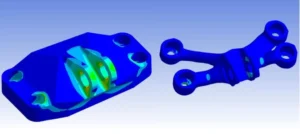
Download: Topology Optimization of a Jet Engine Bracket (Example Model & Course)
Value Proposition
If you want to see structural optimization in a realistic engineering workflow, this example package provides a complete Topology Optimization of a Jet Engine Bracket in ANSYS Mechanical, including a validated verification analysis. It demonstrates how a heavy baseline bracket can be transformed into a lighter concept while maintaining safe load-carrying capability.
What’s Included
-
ANSYS Workbench project for jet engine bracket topology optimization:
-
Geometry
-
Material definition
-
Loads and boundary conditions
-
Optimization setup (design region + preserved regions)
-
-
Step-by-step Tutorial PDF:
-
Definition of design space and constraints
-
How objective and constraints were selected
-
Solver run and interpretation of topology density results
-
Guidance for smoothing / CAD reconstruction and practical detailing
-
-
Validated final design workflow:
-
A verification FEA with refined analysis settings
-
Checks for stress and deflection acceptance criteria
-
-
Formats:
-
ANSYS Workbench project format (compatible with ANSYS 2021R1 and above)
-
Documentation in PDF
-
Software/Skills Required
-
Access to ANSYS Mechanical (Workbench), ideally 2021 or newer
-
Basic familiarity with ANSYS helps, but the tutorial is designed to guide users step-by-step
-
No programming is required; the workflow is configured in the project
How to Use This Example
-
Download and unzip the package into a working directory
-
Open the project in ANSYS Workbench
-
Follow the tutorial PDF to run the topology optimization solution
-
Review the resulting material layout and interpret structural load paths
-
Run the verification analysis included to confirm:
-
Stress limits
-
Displacement limits
-
General performance consistency
-
-
Optional learning step: modify targets and constraints (for example, mass reduction target or displacement constraint) and compare results across runs
Troubleshooting Tips
-
License errors: Some topology optimization features are license-dependent. If the module is unavailable, use the PDF tutorial for learning and review the setup logic.
-
Non-convergence or solver instability: Confirm boundary conditions are correctly applied and that the model is not under-constrained.
-
Rough/jagged topology boundary: This is normal for mesh-based topology outputs. Use the result as a concept and reconstruct smooth geometry for validation.
-
Unrealistic targets: Extremely aggressive mass reduction combined with strict stress limits can lead to poor convergence or unusable shapes. Start with moderate targets and iterate.
Download Links & Further Learning
-
Example Download: Topology Optimization of a Jet Engine Bracket — model + tutorial package
-
Full Course: “Optimization in ANSYS: Learn Design Optimization” — deeper coverage from parameter studies to advanced workflows
-
Consultation: Expert support for formulating optimization problems, building constraints, and custom automation
Common Mistakes in Structural Optimization & How to Avoid Them
Mistake 1: Ignoring Constraints or Using the Wrong Constraints
Issue: Optimizing mass without stress/displacement/frequency constraints can produce a mathematically “optimal” structure that is unsafe or non-functional.
Avoid it: Always define performance constraints that represent real design requirements. If standards apply, ensure constraint values are consistent with allowable stress, serviceability limits, safety factors, and certification rules.
Mistake 2: Not Considering Manufacturing Feasibility
Issue: Topology results can include thin members, enclosed voids, or shapes that require additive manufacturing when the project expects machining or casting.
Avoid it: Use manufacturing constraints where available (minimum thickness, draw direction, symmetry). If not available, post-process the concept into manufacturable geometry, accepting that minor performance trade-offs are normal.
Mistake 3: Too Coarse a Mesh or Excessive Model Simplification
Issue: A coarse mesh may hide stress gradients and lead to incorrect material removal.
Avoid it: Use a mesh that is adequate in critical regions. If optimization must run on a coarser mesh, always re-run verification with refined mesh and adjust the optimization setup if verification shows unexpected hotspots.
Mistake 4: Misinterpreting Topology Optimization Results
Issue: Raw density maps or blocky mesh boundaries are not final CAD. Using them directly can introduce stress risers and manufacturing issues.
Avoid it: Interpret topology output as a structural concept. Reconstruct smooth geometry with fillets and proper transitions, then validate using a high-quality FEA model.
Mistake 5: Neglecting Load Cases and Usage Scenarios
Issue: Optimizing for a single load case can produce a design that fails under another realistic scenario.
Avoid it: Include all critical load cases in the optimization or run multiple studies and combine insights. Always verify the final design under the full design load envelope.
Mistake 6: Expecting One-Click Perfection
Issue: Optimization often needs iteration. Poor settings or unrealistic goals can lead to unstable runs or impractical shapes.
Avoid it: Start with moderate targets and refine. Monitor progress and adjust constraints, step sizes, or algorithm settings if results oscillate or stall.
Mistake 7: Not Validating the Final Design
Issue: Blind trust in the optimization output is risky. Simplified contacts, coarse meshes, or missing failure modes can hide critical weaknesses.
Avoid it: Perform an independent verification analysis and check all relevant failure modes (yield, fatigue, buckling). Have an experienced engineer review the final concept.
FAQs
Q1: What is structural optimization in engineering?
A: Structural optimization is the process of improving a structure’s design using computational methods to meet goals such as lower weight or higher stiffness while satisfying constraints such as stress or displacement limits. The optimizer modifies the design (material layout, shape, or sizes) and runs repeated analyses—typically FEA—until an optimal or near-optimal solution is achieved.
Q2: What are the main types of structural optimization?
A: The main types are size optimization, shape optimization, and topology optimization. Size optimization changes dimensions in a fixed layout, shape optimization refines geometry boundaries, and topology optimization redistributes material inside a design space, creating new holes or load paths.
Q3: How does topology optimization work?
A: Topology optimization starts with a full design space and iteratively removes or redistributes material based on FEA results. You define an objective (for example, minimize compliance / maximize stiffness) and constraints (for example, a volume fraction or stress limit). The algorithm then “carves out” a structure that carries the loads efficiently, often producing organic load-path-driven concepts.
Q4: Which software is best for structural optimization?
A: It depends on your needs and constraints. ANSYS offers a highly integrated GUI-based workflow, Abaqus offers strong flexibility via scripting and add-ons like Tosca, COMSOL is strong for multiphysics optimization, and OptiStruct is often considered an industry reference for topology optimization. In practice, many teams use multiple tools depending on the phase of design.
Q5: Do I need programming skills to do structural optimization?
A: Not always. Many commercial tools support GUI-based optimization setup. However, for advanced workflows, automation, or custom algorithms, scripting (Python, MATLAB) is a major advantage—especially for Abaqus-based optimization loops.
Q6: Is an optimized design always safe and code-compliant?
A: No. The optimizer only “knows” the constraints you give it. If you do not include safety factors, buckling limits, fatigue checks, or specific code provisions, the optimizer will not enforce them. Final code compliance and engineering validation remain mandatory.
Q7: Can structural optimization be used for 3D-printed structures or lattice designs?
A: Yes. Topology optimization is strongly aligned with additive manufacturing and can generate organic structures that are difficult to produce with conventional methods. Many workflows also include lattice optimization, minimum feature size rules, and overhang constraints to match printing capabilities.
Q8: How long does it take to perform a structural optimization?
A: It varies widely. Simple size optimizations can run in minutes. Fine-mesh topology optimization can take hours or days depending on model size, number of iterations, nonlinearities, and hardware. Many engineers run complex studies overnight or on compute clusters.
Q9: What is the difference between structural optimization and FEA (Finite Element Analysis)?
A: FEA evaluates a single design and tells you how it behaves under loads. Structural optimization uses FEA repeatedly to change and improve the design. FEA is the analysis engine; optimization is the decision loop that updates the design.
Q10: When should I use structural optimization in my project?
A: Use it when you have clear performance goals and enough design freedom to benefit from systematic improvement. It is particularly valuable early in design, when topology optimization can shape the concept. It is also useful when mass and performance are critical. If a design is already tightly standardized or code-prescribed, optimization may provide limited benefit beyond confirming sizing choices.