What is Structural Integrity?
Structural integrity is the bedrock of safe, reliable, and durable engineering. It’s not just about making something stand up; it’s about ensuring a structure, component, or system performs its intended function throughout its design life, without catastrophic failure or unacceptable degradation. For engineers across disciplines — from aerospace to civil, mechanical to marine — understanding and applying structural integrity principles is paramount. It’s the difference between a bridge that serves generations and one that collapses prematurely, a medical implant that restores quality of life and one that fails in situ, or a pressure vessel that operates safely and one that poses an environmental and safety hazard.
This guide will dive deep into the world of structural integrity, exploring its core concepts, assessment methodologies, and the powerful tools engineers use to ensure the safety and longevity of critical assets. We’ll cover everything from fundamental principles to advanced simulation techniques like Finite Element Analysis (FEA) and Fitness-for-Service (FFS) assessments.

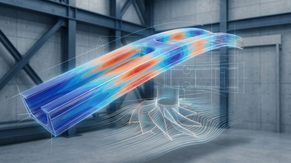
Image: Visualizing stress distribution on a structural beam during analysis.
The Pillars of Robust Structural Integrity
Achieving and maintaining structural integrity is a multi-faceted endeavor that spans the entire lifecycle of a component or system. It relies on a holistic approach, considering several critical factors:
Design for Durability and Performance
- Initial Design Phase: Structural integrity begins on the drawing board. Engineers use advanced CAD tools like CATIA or SolidWorks to conceptualize designs, followed by preliminary analysis using CAE tools.
- Load Path Optimization: Ensuring forces are transferred efficiently and safely through the structure, avoiding stress concentrations.
- Redundancy: Incorporating multiple load paths or backup systems so that the failure of one component doesn’t lead to total system collapse.
- Factor of Safety: Applying appropriate safety margins to account for uncertainties in material properties, loading, and environmental conditions.
Material Selection and Characterization
- Understanding Material Behavior: Selecting materials with properties — strength, toughness, ductility, corrosion resistance, fatigue life — suitable for the operating environment.
- Material Testing: Conducting tensile, impact, fatigue, and creep tests to accurately characterize material response under various conditions.
- Embrittlement Considerations: Accounting for phenomena like hydrogen embrittlement in oil & gas pipelines or irradiation embrittlement in nuclear components.
Manufacturing Quality and Fabrication
- Quality Control: Implementing rigorous inspection processes during fabrication to detect defects like cracks, voids, or welding imperfections.
- Tolerance Management: Ensuring components are manufactured within specified dimensional tolerances to avoid assembly stresses or fit-up issues.
- Post-processing: Considering the impact of manufacturing processes (e.g., heat treatment, welding) on material properties and residual stresses.
In-Service Monitoring and Maintenance
- Condition Monitoring: Utilizing sensors and NDT (Non-Destructive Testing) techniques (ultrasonic, eddy current, radiography) to detect damage or degradation during operation.
- Inspection Schedules: Establishing regular inspection intervals based on predicted degradation rates and operational risks.
- Repair and Remediation: Developing and executing effective repair strategies to restore structural integrity when damage is detected.
Environmental and Operational Considerations
- Temperature Extremes: How materials behave under very high or very low temperatures (e.g., creep at high temps, brittle fracture at low temps).
- Corrosive Environments: Protecting against chemical degradation, stress corrosion cracking (SCC), or hydrogen sulfide (H2S) effects in oil & gas.
- Dynamic Loading: Accounting for vibrations, shocks, and cyclic loads that can lead to fatigue failure.
- Fluid-Structure Interaction (FSI): For components exposed to fluid flow, considering how fluid pressures and forces affect structural response, often analyzed using coupled FEA and CFD (e.g., ANSYS Fluent/CFX or OpenFOAM).
Key Concepts in Structural Integrity Analysis
A deep understanding of these fundamental concepts empowers engineers to predict and prevent failure, ensuring the long-term reliability of structures.
Stress and Strain Analysis
At its core, structural integrity involves managing stress (force per unit area) and strain (deformation). Engineers use analytical methods and FEA tools like Abaqus or ANSYS Mechanical to map stress and strain distributions, identifying areas of high concentration that could lead to failure.
Fatigue Analysis
Many structures are subjected to cyclic loading, leading to fatigue — a progressive, localized, and permanent structural change that occurs in a material subjected to fluctuating stresses and strains. Fatigue analysis predicts component life based on stress ranges, cycles, and material properties (S-N curves, E-N curves). Tools like MSC Nastran often include dedicated fatigue analysis capabilities.
Fracture Mechanics and FFS Level 3
When a crack is present, traditional stress analysis is insufficient. Fracture mechanics provides the framework to assess the integrity of structures containing flaws. Key concepts include stress intensity factor (K), crack tip opening displacement (CTOD), and J-integral.
- Fitness-for-Service (FFS): A critical process, particularly in the oil & gas and power generation industries (e.g., API 579-1/ASME FFS-1 standards), used to determine if equipment containing flaws can continue to operate safely for a specified period.
- FFS Level 3: This is the most detailed and complex level of FFS assessment. It typically involves advanced FEA simulations (using tools like Abaqus or ANSYS Mechanical) to accurately calculate stress intensity factors, J-integrals, or limit loads for complex geometries and loading conditions, often accounting for plasticity and creep effects. It requires significant engineering expertise and computational resources.
Creep and Corrosion
- Creep: The time-dependent deformation of a material under constant stress at elevated temperatures. Common in power plants, jet engines, and high-temperature process equipment.
- Corrosion: The degradation of a material due to chemical or electrochemical reactions with its environment. Can lead to section loss, pitting, and stress corrosion cracking.
Buckling and Instability
Slender structures under compression can fail by buckling — a sudden lateral deflection — even if the material stress is well below its yield strength. FEA tools are crucial for linear (eigenvalue) and non-linear buckling analysis, identifying critical buckling loads and post-buckling behavior.
Tools and Technologies for Structural Integrity Assessment
Modern engineering relies heavily on a suite of sophisticated tools to conduct structural integrity assessments. These tools enable complex analyses that were once impossible.
CAD/CAE Integration
The seamless integration of Computer-Aided Design (CAD) software (e.g., CATIA, SolidWorks) with Computer-Aided Engineering (CAE) tools is fundamental. This workflow allows engineers to move from design conception to detailed analysis efficiently.
Finite Element Analysis (FEA)
FEA is the workhorse of structural integrity. Software like Abaqus, ANSYS Mechanical, and MSC Nastran allows engineers to simulate complex structures under various loads and boundary conditions, predicting stress, strain, deformation, and potential failure modes. They are indispensable for everything from simple linear static analyses to advanced non-linear, dynamic, fatigue, and fracture mechanics simulations (e.g., FFS Level 3).
Computational Fluid Dynamics (CFD)
While primarily for fluid flow, CFD tools like ANSYS Fluent/CFX or OpenFOAM are vital for structural integrity when fluid-structure interaction (FSI) is a concern. This includes aeroelasticity in aerospace, hydrodynamics in marine structures, or thermal stress in heat exchangers where fluid flow dictates temperature distribution.
Material Characterization Tools
Beyond standard mechanical tests, advanced material characterization involves techniques like Scanning Electron Microscopy (SEM), X-ray Diffraction (XRD), and Differential Scanning Calorimetry (DSC) to understand microstructural behavior, defect presence, and phase transformations that impact integrity.
Non-Destructive Testing (NDT)
NDT methods — such as Ultrasonic Testing (UT), Radiographic Testing (RT), Magnetic Particle Testing (MPT), and Eddy Current Testing (ECT) — are crucial for inspecting components for flaws without damaging them. These are vital for in-service monitoring and determining the inputs for FFS assessments.
Automated Workflows: Python & MATLAB
For complex, repetitive, or parametric studies, scripting languages like Python and MATLAB are invaluable. They can automate pre-processing (geometry manipulation, meshing control), post-processing (data extraction, custom plots, fatigue calculations), and even control commercial FEA software via APIs. This significantly boosts efficiency and reduces human error.
Practical Workflow: Conducting a Structural Integrity Assessment with FEA
Here’s a step-by-step approach for a typical FEA-based structural integrity assessment:
- Define the Problem and Scope:
Clearly articulate the objective. What component are you analyzing? What loads, temperatures, and environmental conditions will it experience? What failure modes are you investigating (yield, fatigue, buckling, fracture)? - Gather Data:
Collect all relevant design specifications, material properties (including temperature dependency, fatigue curves), loading conditions (static, dynamic, thermal), boundary conditions, and operational history. - Geometry Preparation (CAD):
Import the CAD model into your FEA pre-processor. Simplify the geometry by removing small features (fillets, holes) that don’t significantly affect global behavior but can complicate meshing and increase computational cost. For complex FFS Level 3 assessments, accurately modeling cracks or flaws is critical. - Material Model Selection:
Choose the appropriate material model (e.g., linear elastic, elastic-plastic, hyperelastic, creep). Ensure you have accurate material properties corresponding to the expected operating temperatures. - Meshing Strategy:
Generate a finite element mesh. This is often the most critical step. Use appropriate element types (solids, shells, beams). Refine the mesh in areas of high stress gradients, stress concentrations (e.g., around holes, fillets, crack tips for FFS), or complex geometry. Aim for mesh quality (aspect ratio, skewness) to ensure accurate results. For fracture mechanics, specialized crack tip elements (e.g., singular elements) are often required. - Apply Loads and Boundary Conditions (BCs):
Accurately represent the physical constraints and external forces. This includes fixed supports, prescribed displacements, pressures, temperatures, and inertial loads. Incorrect BCs are a common source of error. - Solver Setup and Execution:
Configure the solver settings (e.g., linear vs. non-linear, static vs. dynamic, time steps, convergence criteria). Run the simulation using Abaqus, ANSYS Mechanical, or Nastran. Monitor for convergence issues. - Post-processing and Interpretation:
Visualize results (stress, strain, deformation, temperature). Identify peak stresses, assess against yield/ultimate strength, perform fatigue life calculations, or evaluate fracture parameters (K, J, CTOD). Compare results against design allowables or code requirements. - Documentation and Reporting:
Clearly document assumptions, methods, results, and conclusions. This includes mesh details, material inputs, BCs, and interpretation of critical values.
If you’re looking for practical, hands-on experience or need to automate your post-processing, consider exploring downloadable FEA project templates or Python scripting tutorials available through EngineeringDownloads.com. These resources can accelerate your learning and enhance your workflow efficiency.
Verification & Sanity Checks in Simulation
Never take simulation results at face value. A rigorous verification and validation process is essential:
- Mesh Sensitivity Analysis: Rerun the analysis with a finer and coarser mesh. Ensure that critical results (e.g., peak stress, displacement) converge to a stable value as the mesh is refined. If not, your mesh may be too coarse.
- Boundary Condition Impact: Test the sensitivity of your results to slight variations in boundary conditions. Are your supports truly fixed, or is there some flexibility?
- Convergence Criteria: For non-linear analyses, ensure the solver’s convergence criteria (force, displacement, energy) are met at each step. Non-convergence indicates a problem with the setup or solver parameters.
- Hand Calculations & Benchmarking: Compare FEA results for simplified regions or load cases with analytical solutions or known benchmark problems. Even simple beam bending formulas can provide a quick sanity check for displacements and stresses.
- Energy Balance Checks: Many solvers provide an energy balance. Ensure the external work done equals the internal strain energy plus kinetic energy (for dynamic cases).
- Deformation Checks: Visually inspect the deformation plot. Does it make physical sense? Are the deformations in the expected direction? Are there any localized ‘spikes’ that might indicate a bad mesh or singularity?
- Result Interpretation: Question extreme values. Are super-high stresses realistic, or are they a result of a sharp corner singularity or bad element? Understand stress averaging options.
- Experimental Validation (Indirect): If physical test data exists (even from similar components), use it to validate your simulation models. This provides the highest level of confidence.
By systematically applying these checks, you can significantly increase confidence in your simulation results, making them reliable inputs for critical design and FFS decisions.
Common Challenges and Pitfalls in Structural Integrity
Even experienced engineers can stumble. Being aware of common pitfalls can save significant time and resources.
- Underestimating Load Cases: Failing to identify all critical operating, environmental, and accidental load cases (e.g., seismic, impact, thermal cycling).
- Incorrect Material Models: Using simplified linear elastic models when plastic deformation, creep, or fatigue behavior is dominant. Neglecting temperature-dependent material properties.
- Poor Mesh Quality: Using elements that are too coarse, distorted, or have poor aspect ratios, leading to inaccurate stress predictions, especially in critical regions.
- Ignoring Environmental Factors: Neglecting the impact of corrosion, extreme temperatures, or radiation on material degradation and failure mechanisms.
- Lack of Data for FFS Assessments: Insufficient inspection data (flaw size, location), incomplete operational history, or missing material property data can cripple FFS Level 3 assessments.
- Over-reliance on Default Settings: Not understanding the assumptions and limitations of solver default settings, which may not be appropriate for specific analysis types.
Industry-Specific Applications of Structural Integrity
Structural integrity is a universal concern but manifests differently across industries:
- Oil & Gas: Critical for pipelines, pressure vessels, offshore platforms, and refinery equipment. FFS Level 3 assessments are routine for existing infrastructure to manage corrosion, cracks, and remaining life. Python and MATLAB are used for automated pipe stress analysis and data processing.
- Aerospace: Ensuring the integrity of aircraft fuselages, wings, and engine components under extreme fatigue, high temperatures, and complex aerodynamic loads. Lightweighting often pushes designs closer to their limits, demanding highly accurate FEA and FSI (CFD) analysis.
- Biomechanics: Design and assessment of medical implants (hip, knee, dental), prosthetics, and surgical tools. Focus on fatigue life, biocompatibility, and integration with biological tissues. Abaqus and ANSYS are widely used for simulating implant-bone interaction.
Actionable Tips & Best Practices for Structural Engineers
Here’s a table summarizing key practices for maintaining structural integrity:
| Category | Best Practice | Example/Tool |
|---|---|---|
| Design Phase | Integrate SI considerations early | Factor of Safety, Redundant Paths |
| Materials | Thorough material characterization | Tensile tests, Fatigue curves, SEM |
| Analysis | Utilize advanced simulation | Abaqus, ANSYS Mechanical, FFS Level 3 |
| Validation | Rigorous verification & sanity checks | Mesh sensitivity, Hand calculations |
| Monitoring | Implement in-service inspection | NDT (UT, RT), Sensors |
| Automation | Script repetitive tasks | Python, MATLAB for pre/post-processing |
| Documentation | Maintain comprehensive records | Design reports, Inspection logs |
- Integrate Structural Integrity Early: Consider integrity requirements from the initial concept design stage, not as an afterthought.
- Document Everything: Keep meticulous records of design choices, analysis assumptions, material certifications, inspection reports, and repair histories.
- Invest in Continuous Training: The field evolves rapidly. Stay updated on new standards, software features (e.g., advanced capabilities in Abaqus or ANSYS), and analysis techniques.
- Leverage Automation: For repetitive tasks, parametric studies, or complex data processing, develop Python or MATLAB scripts. This frees up engineering time for higher-level problem-solving and reduces manual errors.
- Collaborate Across Disciplines: Structural integrity often requires input from material scientists, manufacturing engineers, and NDT specialists.
By adopting these practices, you can build a robust framework for ensuring structural integrity, contributing to safer designs and more reliable operations.
Conclusion
Structural integrity is more than just a technical discipline; it’s a commitment to safety, reliability, and sustainability in engineering. From initial concept to end-of-life assessment, a diligent and comprehensive approach is required. By mastering advanced analysis tools like FEA, understanding fracture mechanics (including FFS Level 3), and applying rigorous verification checks, engineers can confidently design, operate, and maintain structures that stand the test of time. Embracing automation through Python and MATLAB further enhances this capability, making complex assessments more efficient and accurate.
Remember, the goal isn’t just to prevent failure, but to ensure optimal performance throughout the entire lifecycle of an asset, protecting lives, the environment, and investments.