

In the vast world of engineering simulations, understanding and accurately predicting heat transfer is paramount. While conduction and convection often take center stage, thermal radiation, the transfer of energy via electromagnetic waves, plays a critical — and often dominant — role in numerous applications. From aerospace re-entry vehicles to industrial furnaces, and even the structural integrity of components under extreme temperatures, ignoring radiation can lead to significantly flawed designs and critical failures.
This article dives into the practical aspects of radiation modeling, equipping you with the knowledge to incorporate this crucial heat transfer mechanism effectively into your FEA and CFD simulations. We’ll explore the ‘why’ and ‘how,’ covering methodologies, workflow, common pitfalls, and verification techniques.

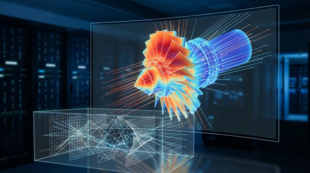
Conceptual diagram illustrating heat transfer by radiation between surfaces.
Understanding Thermal Radiation in Engineering
Thermal radiation is a fundamental mode of heat transfer that doesn’t require a medium. Instead, energy is emitted from surfaces as electromagnetic waves, travels through space, and is absorbed by other surfaces. The amount of radiation emitted by a surface depends on its temperature and surface properties. This makes it distinct from conduction (contact-based) and convection (fluid motion-based).
Why Radiation Modeling is Crucial
For many engineering problems, neglecting radiation is simply not an option. Here’s why:
- High-Temperature Environments: At elevated temperatures (e.g., above 500°C or 900°F), radiation often becomes the dominant heat transfer mechanism, surpassing conduction and convection. Think gas turbines, furnaces, or process heaters.
- Vacuum or Low-Pressure Systems: In environments with little to no fluid, like space or vacuum chambers, convection is negligible. Radiation is the primary, if not sole, means of heat transfer.
- Structural Integrity and FFS Level 3: For assessing fitness-for-service (FFS Level 3) of components in high-temperature service (e.g., in oil & gas or power generation), accurate temperature profiles are vital for predicting creep, fatigue, and fracture. Radiation modeling directly impacts these thermal loads.
- Aerospace Applications: Re-entry vehicles, satellites, and rocket nozzles experience extreme radiative heating and cooling, demanding precise radiation models for thermal management and material selection.
- Electronics Cooling: Even at lower temperatures, radiation can play a significant role in heat dissipation from densely packed electronic components, especially those with high emissivity surfaces.
Key Principles in Radiation Modeling
Before diving into the tools, let’s refresh some core concepts:
Surface Properties
- Emissivity (ε): A measure of a surface’s ability to emit thermal radiation, relative to a black body. Ranges from 0 (perfect reflector) to 1 (perfect emitter, black body). Highly dependent on material, surface finish, and temperature.
- Absorptivity (α): A measure of how much incident radiation a surface absorbs. For opaque surfaces, α = ε.
- Reflectivity (ρ): The fraction of incident radiation reflected by a surface. For opaque surfaces, α + ρ = 1.
View Factors (Shape Factors)
The view factor (Fij) from surface i to surface j represents the fraction of radiation leaving surface i that directly strikes surface j. These are purely geometrical quantities, independent of temperature or surface properties. Calculating view factors accurately, especially for complex geometries, is often the computational bottleneck in radiation modeling.
Blackbody and Gray Body Assumptions
- Blackbody: An idealized surface that absorbs all incident radiation and emits the maximum possible radiation for a given temperature. Emissivity (ε) = 1.
- Gray Body: A real surface where emissivity (ε) and absorptivity (α) are constant for all wavelengths and directions. This is a common and practical assumption in many engineering analyses.
Common Radiation Modeling Approaches in FEA/CFD
Different simulation tools offer various methods, each with strengths and weaknesses:
1. Surface-to-Surface (S2S) Method
Concept: Calculates view factors between all radiating surfaces in an enclosure. Assumes a non-participating medium (e.g., air at ambient pressure). Radiation exchange is then determined based on these view factors and surface temperatures/emissivities. Ideal for enclosed systems where the fluid doesn’t radiate or absorb significantly.
Tools: Abaqus (S2S), ANSYS Mechanical (S2S), ANSYS Fluent (S2S), MSC Nastran.
Pros: Highly accurate for non-participating media, relatively robust, well-established.
Cons: Computationally expensive for large numbers of surfaces due to view factor calculation (scales quadratically or worse), cannot model participating media.
2. Discrete Ordinates Method (DOM)
Concept: Discretizes the angular space into a finite number of directions (ordinates). The radiative transfer equation is solved for each direction and energy group. This method can handle participating media (gases, particles, combustion products) that absorb, emit, and scatter radiation.
Tools: ANSYS Fluent (DOM), OpenFOAM (fvDOM), Abaqus (for participating media using DFLUX subroutine or advanced elements).
Pros: Excellent for participating media, handles complex geometries and non-gray radiation.
Cons: Computationally intensive (solves for multiple directions and potentially multiple energy bands), requires fine mesh for accuracy in optically thick regions.
3. P-1 Model
Concept: A simpler participating media model that approximates the radiative intensity distribution with a truncated spherical harmonics expansion (specifically, the first order). It’s a differential approximation.
Tools: ANSYS Fluent (P-1).
Pros: Computationally less expensive than DOM, suitable for optically thick media where radiation is nearly isotropic.
Cons: Less accurate for optically thin media or where radiation fields are highly anisotropic (e.g., near walls or concentrated sources).
4. Monte Carlo Method (MCM)
Concept: Simulates the random paths of a large number of ‘energy bundles’ or ‘photons’ emitted from surfaces or participating media. Each bundle’s path is traced until it’s absorbed or exits the domain.
Tools: Specialized codes, some CFD packages may offer this (e.g., Fire Dynamics Simulator – FDS, specific research codes).
Pros: Highly accurate for complex geometries, participating media, and spectral effects; conceptually straightforward.
Cons: Extremely computationally expensive, especially for steady-state problems (requires many bundles for low statistical noise), results are inherently statistical.
Choosing the Right Model: A Quick Guide
Here’s a simplified comparison to help you select:
| Feature | S2S Method | DOM | P-1 Model | Monte Carlo |
|---|---|---|---|---|
| Participating Medium | No | Yes | Yes | Yes |
| Computational Cost | Medium (for surfaces) | High | Low-Medium | Very High |
| Accuracy (General) | High (non-part. media) | High | Moderate | Very High (with enough rays) |
| Geometry Complexity | Good | Good | Good | Excellent |
| Optically Thick Media | N/A | Good | Good | Good |
| Optically Thin Media | N/A | Good | Poor | Good |
Practical Workflow for Radiation Modeling
Implementing radiation in your simulations follows a structured approach, regardless of the specific software. Here’s a general guide:
Step 1: Problem Definition and Simplification
- Identify Radiation-Dominant Areas: Determine if radiation is critical. High temperatures, vacuum, or significant temperature differences between surfaces are key indicators.
- Geometry Preparation (CAD/CAE): Simplify your CAD model. Small features that don’t significantly affect radiative heat transfer can often be removed to reduce mesh complexity and view factor calculation time. Tools like CATIA for CAD can streamline this.
- Material Properties: Accurately define thermal conductivity, specific heat, density, and crucially, surface emissivity (ε) for all radiating surfaces. Remember that emissivity can be temperature-dependent.
Step 2: Meshing Considerations
- Surface Mesh (S2S): For S2S, the quality and density of the surface mesh are paramount. Ensure sufficient element count to capture geometric details that influence view factors. Avoid highly distorted elements.
- Volume Mesh (DOM/P-1): For participating media models (DOM, P-1), the volume mesh also needs to be fine enough to resolve gradients in radiative intensity, especially near walls or in regions with high temperature/species gradients.
- Mesh Convergence: Always perform a mesh sensitivity study, particularly for areas with high radiative heat flux. This ensures your results aren’t mesh-dependent.
Step 3: Boundary Conditions and Model Setup
- Thermal Boundary Conditions: Apply known temperatures or heat fluxes to external surfaces. For internal surfaces, the radiation model will solve for surface temperatures based on energy balance.
- External Radiation Sources: If your system is exposed to external radiation (e.g., solar load or a distant hot wall), define these as incident radiation fluxes.
- Radiation Model Selection: Based on the presence of participating media and accuracy requirements, choose the appropriate model (S2S, DOM, P-1).
- Solver Settings: Set appropriate convergence criteria for energy balance and the radiation model itself. For some solvers (like Fluent), radiation is often solved iteratively with the fluid flow and energy equations.
Step 4: Post-Processing and Interpretation
- Heat Fluxes: Analyze radiative heat fluxes on surfaces to identify hot spots or areas of significant heat loss/gain.
- Temperature Distribution: Examine the overall temperature field within solids and fluids. Compare with conduction/convection-only results to quantify radiation’s impact.
- View Factor Visualization: If available, visualize view factors to ensure they are being calculated correctly, especially for complex geometries. This is often an option in tools like Abaqus or ANSYS Mechanical.
For complex radiation models or large-scale simulations, computational resources can be a bottleneck. EngineeringDownloads offers affordable HPC rental services to help you run your models efficiently and extract valuable insights without investing in expensive hardware.
Verification & Sanity Checks for Radiation Models
Just like any simulation, radiation models require rigorous verification to ensure confidence in the results.
1. Basic Checks
- View Factor Summation (S2S): For an enclosed surface, the sum of all view factors from that surface to all other surfaces (including itself) should ideally be 1.0. Deviations indicate meshing issues or calculation errors.
- Temperature Trends: Do the predicted temperatures make physical sense? Hot surfaces radiate to cooler surfaces. If a hot surface in an enclosure gets hotter than expected, check for incorrect boundary conditions or emissivity values.
- Heat Flux Direction: Verify that heat flux vectors are pointing from hotter to cooler regions, or away from heat sources.
2. Mesh Sensitivity Analysis
Run the simulation with different mesh densities, especially for radiating surfaces. Ensure that the total radiative heat transfer and critical surface temperatures do not change significantly with further mesh refinement. This is crucial for both S2S (surface mesh) and DOM/P-1 (volume mesh) models.
3. Analytical or Benchmark Cases
For simpler scenarios (e.g., two parallel plates, concentric cylinders), analytical solutions for radiative heat transfer exist. Compare your simulation results against these to validate your model setup and solver.
4. Energy Balance Check
Confirm that the total heat input (conduction, convection, internal generation) equals the total heat output (conduction, convection, radiation) from your domain. A significant imbalance indicates a problem with the model setup or convergence.
5. Sensitivity to Emissivity
Perform a sensitivity study by slightly varying the emissivity of key surfaces. Observe how this impacts temperature distributions and heat fluxes. This helps understand the robustness of your results to input uncertainties.
6. Convergence Criteria
Ensure that your simulation has converged properly. Monitor residuals for energy and radiation equations. For transient problems, ensure time step independence as well.
Common Pitfalls and Troubleshooting
Radiation modeling can be tricky. Here are typical issues and how to address them:
1. Incorrect View Factor Calculation
- Issue: Unphysical heat distribution, convergence problems.
- Cause: Poor surface mesh quality (highly warped elements, gaps), large element sizes compared to geometric features, shadowing not accounted for correctly.
- Fix: Refine surface mesh, ensure mesh quality. Use specialized tools or options in your software (e.g., Abaqus has options for view factor controls) to improve calculation accuracy. Check for open edges or gaps in your radiating enclosure.
2. Neglecting Participating Media
- Issue: Underprediction of heat transfer in gases or overprediction if the medium absorbs.
- Cause: Assuming S2S in an environment where hot gases significantly absorb or emit radiation (e.g., combustion chambers, high-temperature reactors).
- Fix: Switch to a participating media model (DOM, P-1) and define the radiative properties of the fluid (absorption coefficient, scattering coefficient).
3. Inaccurate Emissivity Values
- Issue: Significant deviation from real-world temperatures.
- Cause: Using generic emissivity values, not accounting for temperature dependence, or surface oxidation/fouling.
- Fix: Research material-specific emissivity data, consider temperature-dependent properties if available, or perform experiments to calibrate values.
4. Solver Divergence
- Issue: Simulation fails to converge, unstable temperature fields.
- Cause: Strong non-linearity of radiation (T^4 dependency), poor initial conditions, bad mesh, or incorrect boundary conditions. Coupling issues with fluid flow.
- Fix: Start with a simpler model (e.g., conduction only) and then introduce radiation. Use smaller time steps for transient analyses. Adjust under-relaxation factors for radiation terms. Ensure your initial temperature guess is reasonable.
Leveraging Automation with Python & MATLAB
For repetitive tasks, parametric studies, or integrating radiation analysis into larger workflows, Python and MATLAB are invaluable:
- Pre-processing: Automate geometry manipulation, mesh generation (e.g., using ANSYS SpaceClaim or scripting in Abaqus/Fluent), material property assignment, and boundary condition definition. This is especially useful for design optimization.
- Post-processing: Extracting specific heat fluxes, temperature profiles, and creating custom plots or reports. This is critical for efficient design reviews and FFS assessments.
- Parametric Studies: Easily vary parameters like emissivity, surface temperature, or even view factor configurations to understand their impact on the system’s thermal performance.
- Coupling: Scripting can help in coupling different physics solvers or external tools if direct coupling isn’t available.
Whether you’re looking to enhance your CAD-CAE workflows or dive deeper into advanced simulation techniques, EngineeringDownloads offers online/live courses and internship-style training to elevate your skills.
Conclusion
Radiation modeling is an indispensable tool in the modern engineer’s arsenal, particularly when dealing with high-temperature applications, vacuum environments, or precision thermal management. By understanding the underlying physics, selecting the appropriate modeling approach, meticulously setting up your simulations, and rigorously verifying your results, you can unlock profound insights into complex thermal systems. Mastering radiation modeling not only ensures the accuracy of your thermal analyses but also enhances the safety, efficiency, and reliability of your designs, from oil & gas infrastructure to advanced aerospace components.


