
Engineering Downloads

Let’s Learn and Collaborate

Engineering Downloads

Wood Analysis Package in Abaqus

207,00 426,00
207,00 426,00
30 people watching this product now!

Material Includes

  • 1- Abaqus Files
  • 2- Document and Paper
  • 3- Tutorial Videos

Audience

  • 1- Mechanical Engineering
  • 2- Civil Engineering
  • 3- Structural Engineering
  • 4- Aerospace Engineering
  • 5- Military and Defense Engineering

What You Will Learn?

  • In this course, you'll learn timber and wood modeling and simulation through 16 comprehensive tutorials, covering various simulations, including bending, compression, low-velocity impact, high-velocity impact, explosion, air blast, flexure, tensile test, thermal analysis, fire, failure, damage, and more.

About Course

Introduction to Wood Analysis and Simulation

Wood analysis and simulation is the study and modeling of wood as an engineering and biological material to predict its performance, behavior, and properties under different conditions. Since wood is a natural, heterogeneous, and anisotropic material (its properties vary depending on the direction of the grain), analyzing and simulating its characteristics is essential for fields such as construction, furniture design, structural engineering, materials science, and even bioenergy research.

In this package, during 16 practical tutorials, you’ll learn all about wood analysis in Abaqus, such as tension, compression, blast, impact, bending, flexure, and other analyses.

1. Why Analyze Wood?

  • Mechanical properties: Wood strength, stiffness, and elasticity determine its ability to bear loads in beams, columns, or flooring.

  • Moisture behavior: Wood absorbs and releases moisture, causing swelling, shrinkage, and dimensional instability.

  • Durability: Susceptibility to decay, insects, and environmental stress affects long-term performance.

  • Sustainability: Wood is renewable, but its properties must be well understood for efficient and safe use.

2. Wood Simulation Approaches

Simulation allows researchers and engineers to predict wood’s behavior without excessive physical testing. Common approaches include:

  • Finite Element Analysis (FEA): Models stress, strain, and deformation of wood structures under loads.

  • Moisture Transport Models: Simulate how water moves within wood, influencing swelling, shrinkage, and mechanical changes.

  • Fracture and Damage Models: Predict crack initiation and propagation, especially in structural timber.

  • Computational Fluid Dynamics (CFD): Used in drying simulations to optimize kiln drying processes.

  • Multiscale Modeling: Connects the microscopic (cellular) structure of wood to macroscopic (structural) properties.

3. Applications of Wood Analysis and Simulation

  • Civil Engineering: Designing safe and efficient wooden bridges, houses, and tall timber buildings.

  • Furniture and Product Design: Ensuring stability, ergonomics, and resistance to environmental changes.

  • Wood Drying and Processing: Optimizing drying methods to reduce defects like warping and cracking.

  • Bioenergy and Pulp Industry: Studying wood combustion, gasification, and pulping processes.

  • Conservation Science: Preserving wooden cultural heritage by simulating aging and degradation.

4. Challenges

  • Wood variability due to species, growth conditions, and defects (knots, cracks).

  • Complex anisotropic behavior (different properties along longitudinal, radial, and tangential directions).

  • Coupling of multiple factors (mechanical, thermal, and moisture effects interact strongly).

Course Content

Example-1: Flexural test of the timber wood beam reinforced with GFRP rod and epoxy Interface
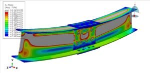
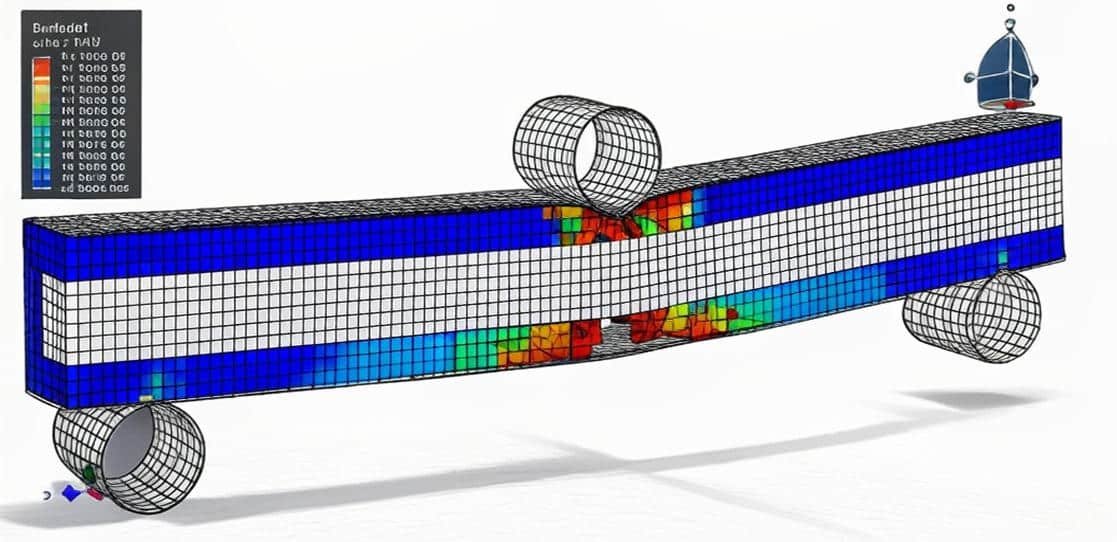
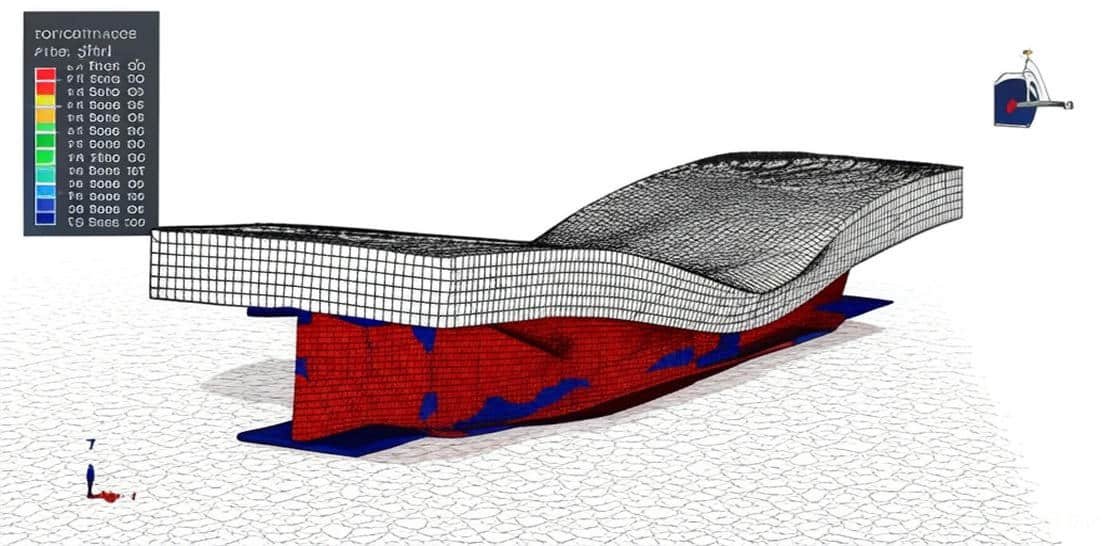
In this lesson, the flexural test of the timber wood beam reinforced with GFRP rod and epoxy Interface is studied. The reinforcement of timber wood beams using Glass Fiber-Reinforced Polymer (GFRP) rods with an epoxy interface represents an innovative approach to enhancing the structural performance of traditional timber elements. This composite system combines the natural advantages of wood with the high tensile strength and corrosion resistance of GFRP materials. The four-point bending test is performed using the general static step. To model wood under bending load, two compression and tension zones are defined as the plastic model. The GFRP is an orthotropic elastic material, and the interface is defined as glue with the CDP model.

  • Abaqus Files
  • Document
  • Tutorial Video-1
    11:29
  • Tutorial Video-2
    15:21
  • Tutorial Video-3
    04:06

Example-2: Analysis of the wood-steel plate connection with a bolt under tension load
In this case, the analysis of the wood-steel plate connection with a bolt under tension load is investigated. A wood-steel plate connection with bolts is a common structural joint used in timber construction to transfer loads between wooden members and steel plates. This type of connection is widely used in beams, columns, trusses, and hybrid structures due to its strength, durability, and ease of assembly. The important thing in the simulation is the material model of the wood; it can be an elastic-plastic model with damage behavior.

Example-3: Wood-Cement wall under seismic loading
In this section, the analysis of the wood-cement wall under seismic loading is done through a comprehensive tutorial. The wood-cement wall is modeled as a three-dimensional solid part. The steel reinforcements are modeled as wire parts. The Concrete Damaged Plasticity model has the potential to represent the complete inelastic behavior of the wood-concrete material in both tension and compression, including damage effects. It can consider both tension and compression damage. The elastic-plastic material model is used for the steel members.

Example-4: Simulation of the air blast load over a laced reinforced concrete with a wood cover
In this lesson, the simulation air blast load over a laced reinforced concrete with a wood cover in Abaqus is studied. The concrete beam is modeled as a three-dimensional solid part. The laced steel reinforcements are modeled as wire parts. The wood cover is modeled as a shell part with some layers. To model concrete behavior under the severe load, the Concrete Damaged Plasticity material model is selected. The Concrete damage plasticity material model represents a constitutive model that is based on a combination of the theory of plasticity and the theory of damage mechanics. This material model is often used in solving geotechnical problems due to its realistic description of the mechanical behavior of concrete material. The elastic-plastic model is selected for the steel reinforcements. The wood is also considered a brittle material with damage behavior. To model blast load, the CONWEP method is a good choice to apply the TNT pressure on the surface of the composite beam.

Example-5: Analysis of a simple composite blast protection wall system(Wood-Soil)
In this case, the analysis of a simple composite blast protection wall system(Wood-Soil) in Abaqus is investigated through a comprehensive tutorial. The wood panel is modeled as a multi-layer shell part. The soil is modeled as a solid part. Explosions can result from several instances, including but not limited to industrial accidents or terrorist operations. The former can be controlled by considering industrial safety requirements, while the latter is far more challenging to maintain. Blind terror does not distinguish between a child, a woman, or an old man. All these are targets for terrorists. Attacks of this nature inside cities targeting civilians and infrastructure have been on the rise in recent years, leaving a massive number of victims in addition to billions of dollars worth of losses. Lately, terrorists have been using innovative and dynamic attack plans to overcome security precautions and surprise security forces. Hence, these attacks have become more complicated to prevent or delay in most scenarios. While protecting structures from blast loading is important, it is clear that terrorist organizations have been focusing on targeting civilians in open urban settings to produce mass casualties. This trend can be attributed to accessibility to the crowds in open spaces and, in some cases, the inability of the structure to resist abnormal loads. This tutorial investigates the possibility of using readily available (low-tech) materials to develop simple blast wall systems to help mitigate damage from explosives. A dynamic explicit step with the CONWEP air blast method is selected. Proper material, boundaries, and meshes are assigned to the parts

Example-6: Rigid impact on the composite panel(Aluminum and Wood)
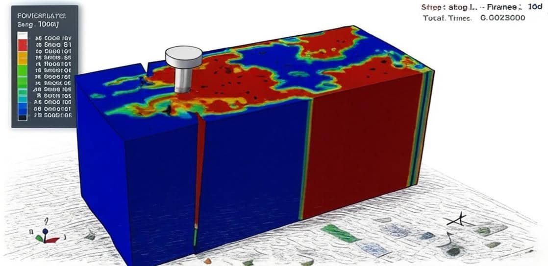
In this section, the Simulation of the rigid impact on the composite panel(Aluminum and Wood) in Abaqus-Damage investigation- is studied. The rigid impactor is modeled as the shell part. The aluminum plate is modeled as a three-dimensional solid part. The wood layer is modeled as a three-dimensional part with some layers. To model aluminum behavior under impact load, the Johnson-Cook hardening and damage model is selected. The Johnson-Cook plasticity model is a particular type of Mises plasticity model with analytical forms of the hardening law and rate dependence, and is suitable for the high-strain-rate deformation of many materials, including most metals. Wood can be modeled through some material models, and it is important to select a material model that considers the damage and its evolution during the impact test.

Example-7: Simulation of the air blast load over a composite beam(Wood+Aluminum)
In this lesson, the simulation of the air blast load over a composite beam(Wood+Aluminum) is investigated through a comprehensive tutorial. The wood slab is modeled as a three-dimensional solid part with tension and compression zones. The aluminum beam is modeled as a three-dimensional shell part. The wood is modeled as an elastic-plastic material in tension and compression zones. The elastic-plastic model and damage behavior are considered for the aluminum beam. The dynamic explicit is appropriate for this type of analysis. The contact between the beam and slab is assumed to be the surface-to-surface contact; besides that, the beam connectors are also used. An aluminum-timber composite (ATC) beam consists of an aluminum girder and a timber slab. The connection between these elements is unproblematic when hexagon head wood screws, glue, or bolts are used. The combination of a metal beam and a timber slab is not new, since steel-timber composite structures have already been investigated. However, aluminium-timber composite (ATC) structures are a relatively new solution in civil engineering.

Example-8: Analysis of the wood timber beam under fire and mechanical bending load
In this lesson, the analysis of the wood timber beam under fire and mechanical bending load in Abaqus software is done. The timber beam is modeled as a three-dimensional solid part. Along with the innovation of new building systems, how we design them must also advance for the systems to be implemented by practitioners. This is especially true for the fire engineering design of novel construction methods, as their performance under fire is investigated. To complete a performance-based design of such systems, a computer model is often required to demonstrate system behavior. Predictive models are often valuable in the design and optimization of such complex structures, provided they can be validated against meaningful data. In the thermal simulation, we have three ways to transfer the heat and energy: 1- Conduction occurs when atoms or molecules interact with each other. It happens most frequently in solids, but also occurs in liquids and gases 2- Convective heat transfer is the transfer of heat between two bodies by currents of moving gas or fluid. In free convection, air or water moves away from the heated body as the warm air or water rises and is replaced by a cooler parcel of air or water 3- Radiation heat transfer is a process where heat waves are emitted that may be absorbed, reflected, or transmitted through a colder body. The Sun heats All heat transfer ways, conduction, convection, and radiation, are considered. First, fire analysis is done and the nodal temperature for each node is written and they are used as the initial condition for the static bending test. The elastic-plastic material depends on the temperature selected for the timber.

Example-9: Simulation of the wood-steel plate connection with a nail under tension load
In this case, the simulation of the wood-steel plate connection with a nail under tension load in Abaqus software is studied. The steel plate and nail are modeled as three-dimensional solid parts. The wooden plate is also a three-dimensional part. s To model material for the nail and plate, the steel material with elastic-plastic and damage behavior is selected. The wood is also modeled as an anisotropic elastic material with damage behavior. The dynamic explicit step is appropriate for this type of analysis. Cross-laminated timber (CLT) is a prefabricated building material that is relatively new to the United States and North America. It consists of no less than three layers of graded, dimensional lumber glued alternating longitudinal and transverse layers to create a panel that can be used for various building applications (walls, floors, etc.). Panels are always constructed in an odd number of layers with the outer layers oriented longitudinally. One use for CLT panels is as shear walls to resist lateral loads due to wind or earthquakes. When CLT shear walls are subjected to lateral loading, tension (uplift) and shear demands are imposed on the fasteners at the base of the panel. Previous research has investigated the performance of fasteners under each of these loading demands.

Example-10: Compression test analysis of a composite column(wood-uhpc-steel cover)
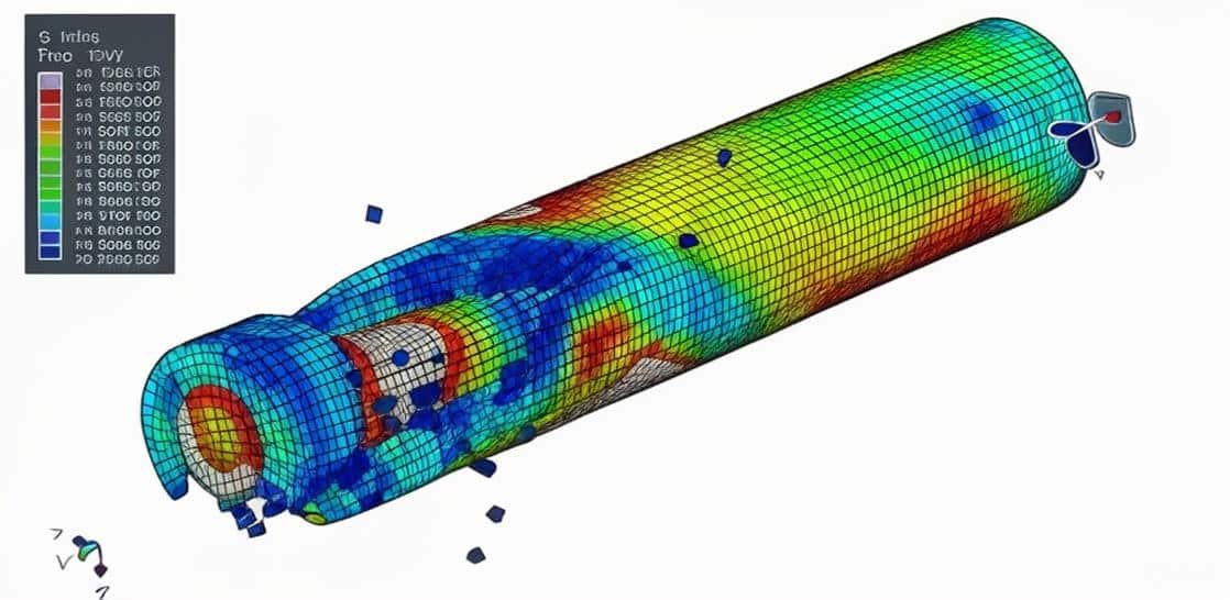
In this section, the compression test analysis of a composite column(wood-uhpc-steel cover) in Abaqus software is investigated through a comprehensive tutorial. The wood core and Ultra-High-Performance-Concrete parts are modeled as three-dimensional solid parts. The steel cover is modeled as a shell part. Wood columns are vertical structural components made from timber, designed to bear loads and transfer them to the foundations. The elastic-plastic material model is selected to demonstrate the wood's behavior under compression load. To model the UHPC, the Concrete Damage Plasticity is considered. The model is a continuum, plasticity-based, damage model for concrete. It assumes that the two main failure mechanisms are tensile cracking and compressive crushing of the concrete material. Two types of materials for concrete are used. In the second model, to consider full failure, the failure strain is implemented. The elastic-plastic data with the ductile damage criterion were also selected for the steel cover

Example-11: Analysis of the air blast of a composite column(wood-concrete-CFRP)
In this lesson, the analysis of the air blast of a composite column(wood-concrete-CFRP) in Abaqus is done through a practical tutorial. The wood is modeled as a three-dimensional solid part with two layers of tension and compression. The concrete is modeled as a three-dimensional solid part. The steel bars and strips are modeled as three-dimensional wire parts. The CFRP is modeled as a shell part. A dynamic explicit step with a general contact capability is a proper choice in this example. The perfect contact is assumed among all the internal surfaces. The steel reinforcements are embedded inside the host. The CONWEP air blast load is selected to define the blast procedure of the TNT charge. The elastic and plastic model is considered to model the wood behavior under tension and compression loads. Hill’s function coefficients are used to describe the plastic behavior. To model concrete material, the Concrete Damaged Plasticity is selected. The model is a continuum, plasticity-based, damage model for concrete. It assumes that the two main failure mechanisms are tensile cracking and compressive crushing of the concrete material. The elastic-plastic model and ductile damage criterion are selected for the steel reinforcement. The CFRP material data is defined as an elastic model with Hashin’s damage criterion. Damage initiation refers to the onset of degradation at a material point. In Abaqus, the damage initiation criteria for fiber-reinforced composites are based on Hashin’s theory. These criteria consider four different damage initiation mechanisms: fiber tension, fiber compression, matrix tension, and matrix compression.

Example-12: Simulation of the bending test of a composite beam(wood-UHPC-Steel)
In this case, the simulation of the bending test of a composite beam(wood-UHPC-Steel) in Abaqus is investigated. The wood is modeled as a three-dimensional solid part with two layers; the top layer is in compression, and the bottom layer is in tension. The Ultra-High-Performance-Concrete is modeled as a three-dimensional solid part. The steel cover is modeled as a shell part. To model the UHPC material, the Concrete Damaged Plasticity is selected. The model is a continuum, plasticity-based, damage model for concrete. It assumes that the two main failure mechanisms are tensile cracking and compressive crushing of the concrete material. The elastic-plastic behavior with Hill’s function coefficients is considered to model wood behavior under tension and compression. To model steel material, the elastic-plastic data with a ductile damage criterion is selected. The dynamic explicit step with a general contact capability is used. The contact between the internal surfaces is assumed as a perfect contact. The surface-to-surface contact with friction as a contact property is used to define the contact between the rigid body and the steel cover. The proper boundary conditions and mesh are assigned to all parts. To consider the full failure of the concrete, in the second model, the strain failure model is considered to observe the full failure of the concrete.

Example-13: Air blast explosion over a timber wood beam reinforced with CFRP
In this lesson, the air blast explosion over a timber wood beam reinforced with CFRP in Abaqus is done through a comprehensive tutorial. The two wood beam layers are modeled as three-dimensional solid parts. The CFRP sheet is modeled as a three-dimensional shell part. Damage initiation refers to the onset of degradation at a material point. In Abaqus, the damage initiation criteria for fiber-reinforced composites are based on Hashin’s theory. These criteria consider four different damage initiation mechanisms: fiber tension, fiber compression, matrix tension, and matrix compression. To model CFRP material, the elastic model with the failure stress option and Hashin’s damage criterion is used. To model wood behavior, the engineering elasticity with plastic model is selected. The dynamic explicit step is appropriate for this type of analysis. The cohesive interaction between the wood layers and CFRP with wood is selected. To define cohesive surface interaction, the stiffness and the damage model are considered. The CONWEP air blast load is used in this tutorial to consider the blast load on the timber.

Example-14: Low-energy impact on the multilayered wood panel
In this section, the analysis of the low-energy impact on the multilayered wood panel in Abaqus is studied. The rigid ball is modeled as a three-dimensional shell part with a specific mass. Each wood panel is modeled as a three-dimensional solid part, and between the layers, the cohesive contact is selected. Damage initiation refers to the onset of degradation at a material point. In Abaqus, the damage initiation criteria for fiber-reinforced composites are based on Hashin’s theory. These criteria consider four different damage initiation mechanisms: fiber tension, fiber compression, matrix tension, and matrix compression. In this tutorial, the Hashin damage model is considered for the wood panel under impact. The engineering elastic model, also a plastic model with Hill’s theory, can be used. The dynamic explicit step with general contact capability is selected. The cohesive behavior as a contact property by using stiffness, damage, and its evolution is defined to model interlaminar failure.

Example-15: Dynamic four-points bending of the timber wood beam reinforced with a CFRP rod and glue
In this lesson, the dynamic four-point bending of the timber wood beam reinforced with a CFRP rod and glue in Abaqus is done through a practical tutorial. The wood beam is modeled as a three-dimensional solid part with two compression and tension sections. The adhesive and CFRP rod are also modeled as three-dimensional solid parts. The material of wood and CFRP tapes is Elastic/Engineering Constants and Plastic/Isotropic with Potential. Adding the Potential option enables to definition of strength in respective directions using Hill’s function coefficients. The material of adhesive layers is Elastic/Traction and Quads Damage. The described example assumes the properties of polyurethane (PUR) glue. Both static and dynamic steps can be selected, but in this tutorial, to reduce the time of the simulation, a dynamic explicit step with a mass scale is used. The perfect contact is assumed between the adhesive andthe CFRP, adhesive, and wood beam.

Example-16: Analysis of the Wood-Glue-CFRP beam under the dynamic four-points bending test
In this lesson, the analysis of the Wood-Glue-CFRP beam under the dynamic four-point bending test is done. The wood beams are modeled as three-dimensional solid parts, the adhesive parts are modeled as three-dimensional solid parts, the CFRP is also solid, and the rollers are modeled as rigid shell parts. Structural elements made of combining wood with FRP composites are the current research topic undertaken by many scientists. There are several known ideas for strengthening and reinforcing solid and glued laminated timber. For strengthening solid wood, the first method is gluing strips to the bottom of a girder on the entire cross-section width. The second method is gluing strips to the bottom of the girder, but not on the entire cross-section width. Another method is to fold the composite onto the vertical planes of the girders. The last method is cutting a cross-section and gluing a plate into the prepared incision. All deformable parts, like wood beams, CFRP, and adhesives, are modeled as three-dimensional solid parts. Material of wood and CFRP tapes is Elastic/Engineering Constants and Plastic/Isotropic with Potential. Adding a Potential option enables defining strength in respective directions using Hill’s function coefficients. Material of adhesive layers is Elastic/Traction and Quads Damage. The described example assumes properties for polyurethane (PUR) glue. Both static general and dynamic explicit steps can be selected. To decrease the time of the simulation, the dynamic explicit step with mass scale is considered. The tie or ideal contact is assumed between CFRP-adhesive and Wood-adhesive. The surface-to-surface contact with contact property is selected to define the contacts among the rigid bodies with wood beams. The proper boundary conditions and load are assigned to the rigid parts. The mesh should be fine to obtain the correct results.

Reviews

Student Ratings & Reviews

No Review Yet
No Review Yet
207,00 426,00
30 people watching this product now!

Material Includes

  • 1- Abaqus Files
  • 2- Document and Paper
  • 3- Tutorial Videos

Audience

  • 1- Mechanical Engineering
  • 2- Civil Engineering
  • 3- Structural Engineering
  • 4- Aerospace Engineering
  • 5- Military and Defense Engineering

Related  Products

See more

Want to receive push notifications for all major on-site activities?