Engineering Downloads

Let’s Learn and Collaborate

Engineering Downloads

Welding Analysis and Simulation Package in Abaqus

219,00 480,00
219,00 480,00
14 people watching this product now!

Material Includes

  • 1- Abaqus files+Codes+Subroutine
  • 2- Tutorial videos
  • 3- Related references

Audience

  • 1- Materials Engineering
  • 2- Mechanical Engineering
  • 3- Aerospace Engineering
  • 4- Manufacturing Engineering

What You Will Learn?

  • You will learn various welding simulation techniques, including friction stir welding with ABS, aluminum, and steel materials, spot welding simulations, water jet impact modeling, pipe welding using DFLUX subroutine, arc, and fusion using DFLUX subroutines, and explosive welding in Abaqus.
  • This package covers everything that you need to understand all welding methods in Abaqus.

About Course

🔹 Introduction to Welding Analysis and Simulation

Welding is one of the most widely used manufacturing processes in industries such as automotive, aerospace, shipbuilding, energy, and construction. While it provides strong and durable joints, welding introduces complex thermal, mechanical, and metallurgical phenomena that can significantly influence the performance of the final product.

1. Why Welding Analysis and Simulation?

  • Welding involves localized heating and cooling, leading to temperature gradients, residual stresses, and distortions.
  • Mechanical properties can change due to phase transformations and microstructural evolution.
  • Traditional trial-and-error approaches for optimizing welding processes are expensive, time-consuming, and limited.
  • Numerical simulation tools (e.g., Abaqus, ANSYS, SYSWELD) allow engineers to predict, analyze, and optimize welding processes before physical experiments.

2. Key Aspects of Welding Simulation
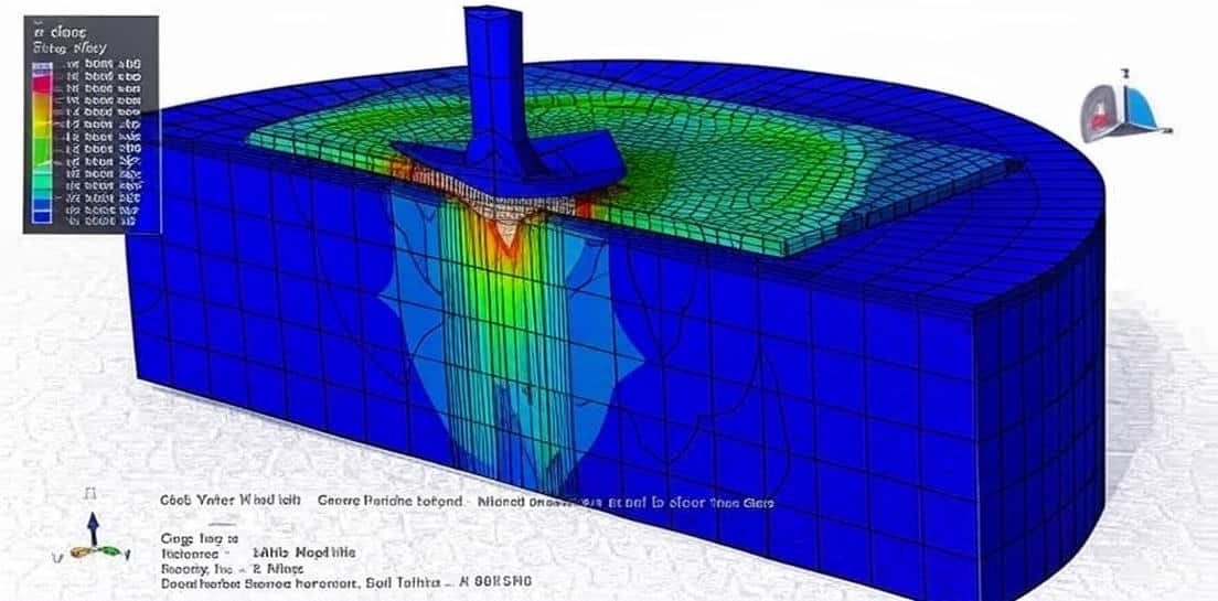
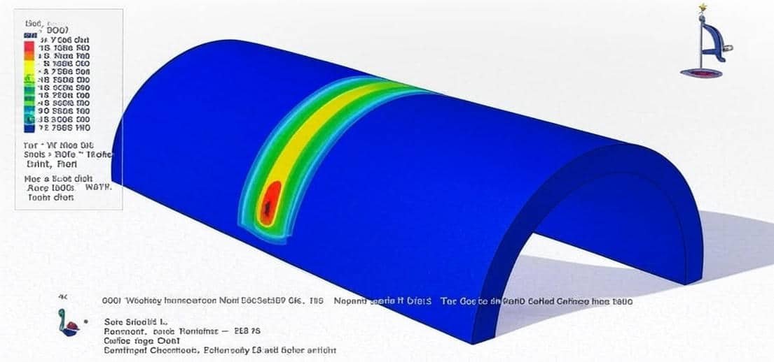
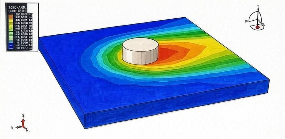
  • Thermal Analysis
    • Predicts heat distribution, cooling rates, and temperature history.
    • Models heat sources (e.g., Goldak double ellipsoidal model).
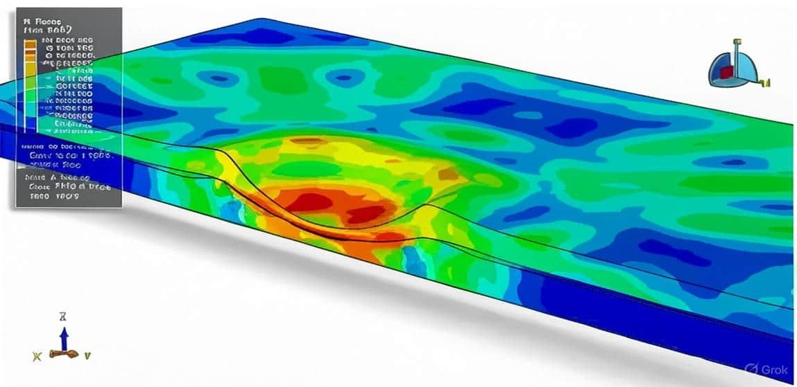
  • Structural/Mechanical Analysis
    • Determines residual stresses and distortions caused by thermal expansion and contraction.
    • Helps prevent warping, cracking, and dimensional inaccuracies.
  • Metallurgical Analysis
    • Simulates phase transformations, hardness distribution, and microstructural evolution in Heat-Affected Zones (HAZ).
    • Critical for ensuring mechanical integrity.
  • Coupled Thermo-Mechanical Analysis
    • Integrates heat transfer with mechanical response for realistic predictions.

3. Applications of Welding Simulation

  • Automotive & Aerospace: lightweight structures with precise tolerance.
  • Shipbuilding: large welded panels with distortion control.
  • Oil & Gas / Energy: welding of pressure vessels and pipelines.
  • Nuclear Industry: high-integrity welds with strict safety requirements.

4. Benefits of Welding Simulation

  • Reduces costly experimental trials.
  • Improves product quality and reliability.
  • Optimizes welding parameters (speed, heat input, sequence).
  • Enhances safety by predicting potential weld defects.
  • Shortens design and production cycles.

👉 In Abaqus, welding simulations are usually performed using coupled temperature-displacement analyses, with specialized subroutines or packages to model moving heat sources, filler deposition, and metallurgical changes.

This package includes 14 practical tutorials that cover all aspects of welding simulation and analysis. 

Course Content

Example 1: Modeling of the friction stir welding of acrylonitrile butadiene styrene(ABS) polymer
In this tutorial, the Simulation of the friction stir welding of acrylonitrile butadiene styrene polymer in Abaqus has been investigated. Polymer materials have seen their growth in leaps and bounds, setting their foot in almost all manufacturing industries due to their excellent strength-to-weight ratio with enhanced toughness and low cost. Polymer joints are extensively used for automobile applications. One example is automotive tail-lights and indicators, in which a clear or tinted PC part is joined to an opaque ABS body. Polymers have different rheological properties, especially in terms of melt viscosity, and thus, the flow behaviour is also different from metals, which may be the main reason for the diversity of process parameters in FSW. Polymers which having higher melt temperature and viscosity require a higher tool rotational speed and a lower tool traverse speed to obtain adequate heat and finally, high joint efficiency. It is very challenging to join dissimilar polymers owing to the differences in their mechanical, chemical, thermal, metallurgical, and physical properties; however, similar material exhibits good material compatibility, which leads to more efficient joining. The ABS part is modeled as a three-dimensional Eulerian part. The tool is modeled as a three-dimensional solid part. To model tool behavior, steel material with elastic-plastic data and thermal parameters is used. To model ABS material, elastic data, and Johnson-Cook plasticity with thermal conductivity, specific heat, and… is used. The dynamic temp explicit step is appropriate for this type of analysis. The friction coefficient with the heat generation parameter is used to define the contact property. The rigid body constraint is implied for the tool to reduce the calculation volume during the FSW process. The fixed boundary condition is assigned to the sides of the Eulerian part, and axial and rotational velocity to the tool. The uniform material assignment is used to model the Eulerian material location.

  • Abaqus files
  • Video
    00:00
  • Documents

Example 2: Analysis of Friction Stir Spot welding by using the ALE method
In this lesson, the analysis of Friction Stir Spot welding by using the ALE method is studied. In this simulation, friction stir spot welding using the Arbitrary Lagrangian-Eulerian method has been investigated. Aluminium alloy is used as the base material, and the tool is modeled as a rigid body. A dynamic explicit step, modified to consider the temperature variable, has been used. available to join aluminum: tungsten inert gas (TIG), metal arc welding (MIG), and resistance spot welding (RSW), to name a few. All the above methods require heating/melting of the aluminum alloy base metal. Other methods that do not require the melting of aluminum alloy base metal are self-piercing riveting (SPR), clinching, and bonding with structural adhesives, to name a few. Spot friction stir welding (SFW), also known as friction stir spot welding (FSSW), is a novel variant of the“linear” friction stir welding (FSW) process developed by Mazda Corporation and Kawasaki Heavy Industries in 2003 as a solid-state joining technique to join aluminum alloys. FSW, which was invented by The Welding Institute (TWI) in 1991, and SFW are promising joining processes that have shown potential practical applications for welding aluminum alloys in the automotive industry. FSW and SFW have been successfully used to produce high-quality joints, and these methods also make it possible to join high-strength aluminum alloys on the basis of tensile strength, process time, and cost (equipment and running cost). Aluminum alloy sheets having a wide range of thicknesses were joined using the above three methods. It was concluded that the lap-shear strength of joints produced by the SFW process was comparable to that produced by RSW or SPR; however, the process time required to join the sheets using SFW increased monotonically with increasing thickness. SFW process advantages are lower power consumption than RSW and lower running costs. Furthermore, unlike RSW, no weld spatter occurs during the SFW process, resulting in a better work environment. Other merits of the SFW process include long tool life, high productivity, and high reliability.

Example 3: Simulating a Water Jet Impact: Simplified Spot Welding Process

Example 4: Simulation of the thermal stress analysis of arc welding between two pipes by using the DFLUX subroutine
In this section, the simulation of the thermal stress analysis of arc welding between two pipes by using the DFLUX subroutine is investigated through a comprehensive tutorial. Arc welding is one of several fusion processes for joining metals. By applying intense heat, metal at the joint between two parts is melted and caused to intermix – directly, or more commonly, with an intermediate molten filler metal. Upon cooling and solidification, a metallurgical bond is created. Since the joining is an intermixture of metals, the final weldment potentially has the same strength properties as the metal of the parts. This is in sharp contrast to non-fusion processes of joining (i.e., soldering, brazing, etc.) in which the mechanical and physical properties of the base materials cannot be duplicated at the joint. In this tutorial, steel material for pipes and the DFLUX subroutine to create non-uniform heat distribution have been used. All material data depend on temperature, and for the analysis weld process Displacement Couple with Temperature step was used.

Example 5: Friction Stir Welding Process Using the Coupled Eulerian Lagrangian Method
In this case, the friction Stir Welding Process Using the coupled Eulerian-Lagrangian Method in Abaqus is considered. Friction Stir Welding (FSW) is a solid-state joining process that relies on frictional heating and plastic deformation realized at the interaction between a non-consumable welding tool that rotates on the contact surfaces of the combined parts. The experiments are often time-consuming and costly. To overcome these problems, numerical analysis has frequently been used in recent years. Several simplified numerical models were designed to elucidate various aspects of the complex thermo-mechanical phenomena associated with FSW. This video investigates a thermo-mechanical finite element model based on the Coupled Eulerian Lagrangian method to simulate the friction stir welding of the AA 6082-T6 alloy. Abaqus/cae software is used in order to simulate the welding stage of the Friction Stir Welding process. This video presents the steps of the numerical simulation using the finite elements method, in order to evaluate the boundary conditions of the model and the geometry of the tools by using the Coupled Eulerian Lagrangian method. During the simulation rotation of the tool causes a huge amount of heat and increased aluminium temperature. This simulation was made in three steps, and a dynamic temperature explicit has been applied.

Example 6: Analysis of the fusion pipe welding using the DFLUX subroutine
In this lesson, the analysis of the fusion welding and investigation of residual stress during the process is conducted by using the DFLUX subroutine in Abaqus. Fusion welding has been a key factor in the creation of modern civilization due to its key role in construction practices. Besides bolts and rivets, there are no other practical methods for joining pieces of metal securely. Fusion welding is used in the manufacture of many everyday items, including airplanes, cars, and structures. A large community uses both arc and flame contact welding to create artwork. To model non-uniform heat distribution DFLUX subroutine on the circular pass over a steel pipe has been implemented. During the process, residual stress was created by moving heat.

Example 7: Arc welding process of steel pipe by usingthe DFLUX subroutine-Temperature analysis
In this section, the arc welding process of steel pipe by using the DFLUX subroutine-Temperature analysis is investigated. Fusion welding is a joining process in which the coalescence of metals is achieved by fusion. This form of welding is widely employed in fabricating structures such as ships, offshore structures, steel bridges, and pressure vessels. In this study, the heat from the moving welding arc was applied as a volumetric heat source with a double ellipsoidal distribution proposed by the Goldak model. The moving heat source was modeled by ABAQUS user subroutine DFLUX in the ABAQUS code. As for the boundary conditions applied to the thermal model, convection and radiation were both used as interactions.

Example 8: Friction Stir Welding-SPH method
In this lesson, the analysis of the friction stir welding by using the SPH method is done through a practical tutorial. The friction stir welding (FSW) process is quickly becoming the joining method of choice for aluminum alloys. The solid-state process is able to form high-fidelity welds at excellent throughput rates. Because of the solid-state nature of the method, many types of defects are avoided that are associated with melting and solidification in conventional fusion welding processes. Nevertheless, depending on the process parameters, FSW joints can have volumetric defects that are detrimental to the ultimate strength of the joint. In this video, Simulation Friction Stir Welding by using the SPH method in Abaqus-Thermal analysis has been investigated. Abaqus doesn’t support SPH element coupled with temperature degree, ie, PC3DT element, so by changing some points, temperature has been applied to this type of element. This analysis contains three steps, and during each step, stress and temperature changed.

Example 9: Water Jet Spot Welding Model of aluminum plates
In this lesson, the water jet spot welding model of the aluminum plates is studied during a practical tutorial. To gain an understanding of the mechanism of material damage and removal during high-speed liquid impact and to understand the magnitude and spatial distribution of the transient pressures caused by such an impact on a solid surface would be helpful. The water jet spot welding tests were performed using the Abaqus software. This consisted essentially of a water column and a 4.2mm diameter nozzle. Target blocks of aluminium, polished 50mm×50mm×1mm cladding plates of aluminium were used in the tests. The separation distance between the target and flyer plate varied between 0.5 . All parts are modeled as three-dimensional and deformable. To model water behavior Us-Up equation and the Lagrangian method have been applied. The Johnson-Cook material model is used to define aluminium plate material. Dynamic-Temp Explicit is appropriate for this analysis, and proper boundary and interaction have been implemented. During water jet impact, the flyer plate moved toward the base plate, and after contact small joint was created between the two plates.

Example 10: Analysis of the impact welding process-Lagrangian approach
In this section, the analysis of the impact welding process-Lagrangian approach in Abaqus software, is done through a comprehensive tutorial. Today, major innovations suggest the use of dissimilar material combinations to meet new design criteria such as mass light weighting, structural reinforcements, or other specific fictionalization. The development of functional material combinations has seen a growing interest in several engineering fields. Solutions can, however, be limited by the capability of the bulk materials to be joined together. In this video impact welding process in Abaqus by using the Lagrangian approach has been investigated. This simulation aims to monitor residual stress that occurs in the process. Dynamic Explicit procedure is appropriate for this analysis, but for thermal analysis, Dynamic-Temp-Explicit with a very small mesh is needed for observing the temperature field.

Example 11: Simulation of the arc welding process of a steel plate using the DFLUX code
In this case, the simulation of the arc welding process of a steel plate using the DFLUX code is investigated. Arc welding is a fusion welding process where heat is generated by an electric arc formed between an electrode and the workpiece. The intense heat of the arc (up to ~6000 °C) melts the base material and, if used, a filler material, forming a strong joint upon solidification. Arc welding introduces a moving localized heat source. In Abaqus, this can be implemented using the DFLUX user subroutine, which defines the heat flux distribution as a function of space, time, and process parameters. A widely used model is Goldak’s double-ellipsoidal heat source, which captures the front and rear distribution of the arc heat input. DFLUX Subroutine: Defines heat flux distribution at each integration point. Moves the heat source with a time-dependent welding speed.

Example 12: Simulation fusion welding of a steel plate
In this lesson, the fusion welding of a steel plate in Abaqus is studied through a practical tutorial. Arc welding is a fusion welding process where heat is generated by an electric arc formed between an electrode and the workpiece. The intense heat of the arc (up to ~6000 °C) melts the base material and, if used, a filler material, forming a strong joint upon solidification. Main Types of Arc Welding: Shielded Metal Arc Welding (SMAW / Stick Welding): Uses a flux-coated consumable electrode. Gas Metal Arc Welding (GMAW / MIG): Uses a wire electrode and shielding gas. Gas Tungsten Arc Welding (GTAW / TIG): Uses a non-consumable tungsten electrode with inert gas shielding. Flux-Cored Arc Welding (FCAW): Similar to MIG but uses a tubular wire filled with flux. Submerged Arc Welding (SAW): Arc submerged under a layer of granular flux.

Example 13: Explosive Welding Between Titanium and Steel Pipes
In this section, the explosive welding between titanium and steel pipes is done in Abaqus. What is Explosive Welding (EXW)? Explosive welding is a solid-state welding process that uses a controlled detonation of explosives to accelerate one metal plate (flyer) against another (base) at very high velocity. Unlike arc or fusion welding, EXW does not melt the metals. Instead, the high-velocity impact causes plastic deformation at the interface, producing a wavy, metallurgical bond. In simulation (Abaqus/Explicit), explosive welding is modeled using shock physics, material plasticity, and contact algorithms to predict the flyer velocity, jetting, and interface bonding mechanism.

Example 14: Explosive Welding Between Copper and Aluminum Pipes
In this lesson, the simulation of the Explosive Welding Between Copper and Aluminum Pipes is investigated through a tutorial video. In simulation (Abaqus/Explicit), explosive welding is modeled using shock physics, material plasticity, and contact algorithms to predict the flyer velocity, jetting, and interface bonding mechanism. Two pipes have been modeled as axisymmetric parts and TNT-like them. For modeling TNT behavior JWL equation of state has been used. Today, major innovations suggest the use of dissimilar material combinations to meet new design criteria such as mass light weighting, structural reinforcements, or other specific functionalization. The development of functional material combinations has seen a growing interest in several engineering fields. Solutions can, however, be limited by the capability of the bulk materials to be joined together. This is the case of metals assembly with different melting temperatures when a conventional welding process is used. During the process copper pipe moves like a flyer pipe toward the aluminium pipe. TNT created huge pressure on the flyer pipe and caused a joint as a weld between the interference surfaces of two pipes.

Reviews

Student Ratings & Reviews

No Review Yet
No Review Yet
219,00 480,00
14 people watching this product now!

Material Includes

  • 1- Abaqus files+Codes+Subroutine
  • 2- Tutorial videos
  • 3- Related references

Audience

  • 1- Materials Engineering
  • 2- Mechanical Engineering
  • 3- Aerospace Engineering
  • 4- Manufacturing Engineering

Related  Products

See more

Want to receive push notifications for all major on-site activities?