Engineering Downloads

Let’s Learn and Collaborate

Engineering Downloads

Steel Structure Analysis Package

249,00 549,00
249,00 549,00
10 people watching this product now!

Material Includes

  • 1- Abaqus Files
  • 2- Documents
  • 3- Tutorial Videos

Audience

  • 1- Civil Engineering
  • 2- Structural Engineering
  • 3- Mechanical Engineering

What You Will Learn?

  • This package includes 21 tutorials that will learn you the steel structure analysis deeply, it considers all the matters such as beam, column, beam-column joint, cyclic loading, failure, bolt modeling, steel angle, stiffeners, composite beam, composite column, static approach, dynamic model, and many other subjects. This full course is a comprehensive one to understand the steel members analysis.

About Course

Introduction to Steel Structure Analysis and Simulation

Steel structures are widely used in bridges, towers, industrial plants, and high-rise buildings because of steel’s high strength-to-weight ratio, ductility, and predictable behavior. To ensure safety and efficiency, engineers use structural analysis and simulation tools to model how steel members (beams, columns, frames, trusses, etc.) behave under different loading and boundary conditions.

This package includes 21 practical tutorials, and during this journey, you’ll be a master in steel structure analysis. 

1. Basic Components of Steel Structures

  1. Beams
    • Horizontal members are designed to resist bending and shear.
    • Common shapes: I-beams (wide flange), channels, hollow sections.
    • Carry loads mainly transverse to their longitudinal axis.
  2. Columns
    • Vertical members are designed to resist axial compression and sometimes bending.
    • Critical aspect: buckling stability.
  3. Frames
    • Assemblies of beams and columns are connected.
    • Rigid frames transfer moments between members.
    • Braced frames use diagonal bracing to resist lateral loads.
  4. Trusses
    • Lightweight triangulated frameworks where members carry mostly axial forces.
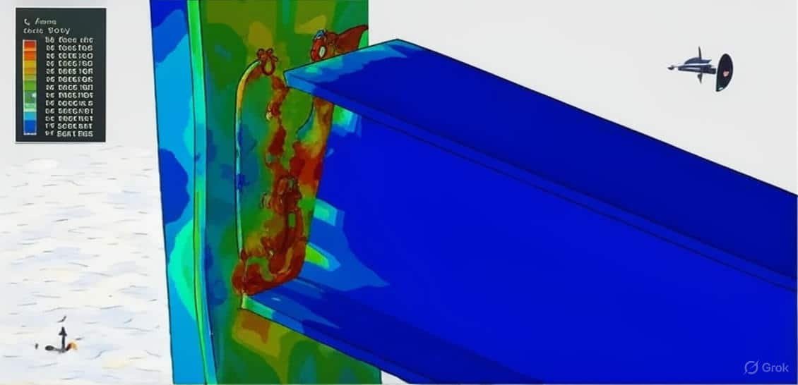
  5. Connections/Joints
    • Can be pinned (hinged) → allows rotation, no moment transfer.
    • Rigid (moment) → resist rotation, transfer moments.
    • Bolted or welded, depending on design.
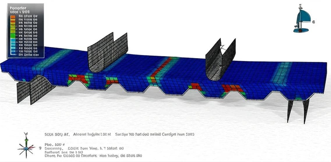
  6. Plates and Shells
    • Thin steel plates are used in tanks, silos, bridges, and building floors.

2. Structural Analysis Basics

Structural analysis answers: How does a structure deform, and what internal forces develop under applied loads?

  1. Load Types
    • Dead loads (self-weight, permanent equipment)
    • Live loads (people, furniture, vehicles)
    • Environmental loads (wind, snow, seismic, temperature effects)
  2. Analysis Methods
    • Classical methods (hand calculations): bending theory, truss analysis, moment distribution, portal method.
    • Matrix methods: stiffness method, flexibility method → foundation of modern software.
    • Finite Element Method (FEM): most widely used today for complex geometries and loading.
  3. Key Response Quantities
    • Displacements (deflections, rotations)
    • Internal forces (axial, shear, bending moment, torsion)
    • Stresses and strains
    • Buckling capacity and vibration modes

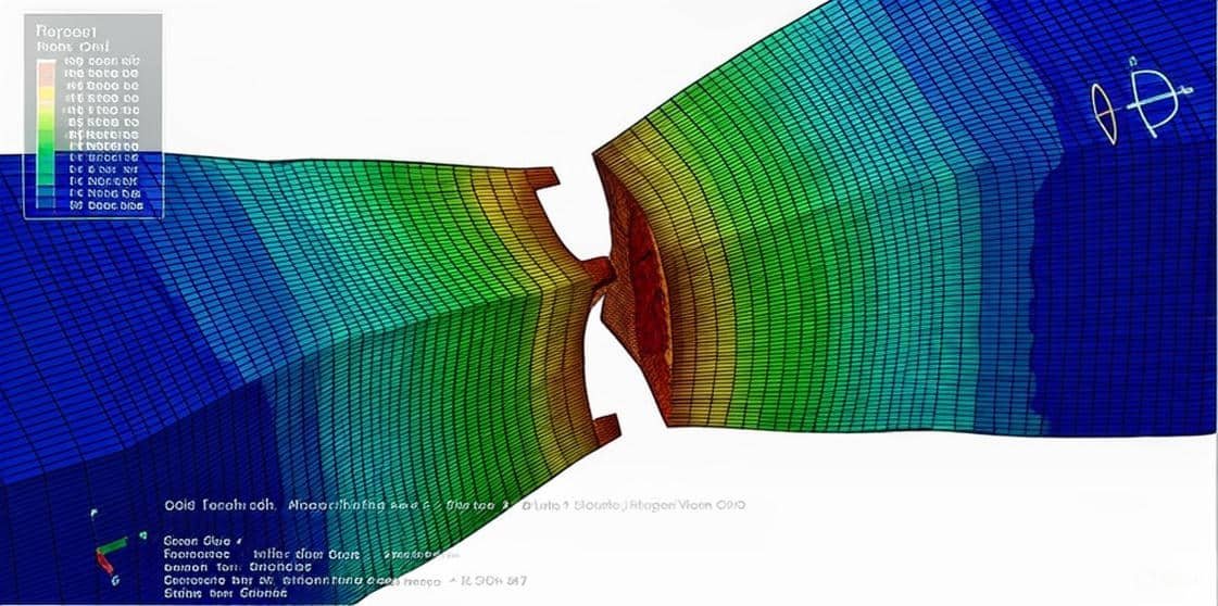
3. Simulation of Steel Structures

Modern engineering relies heavily on simulation to predict structural behavior more accurately.

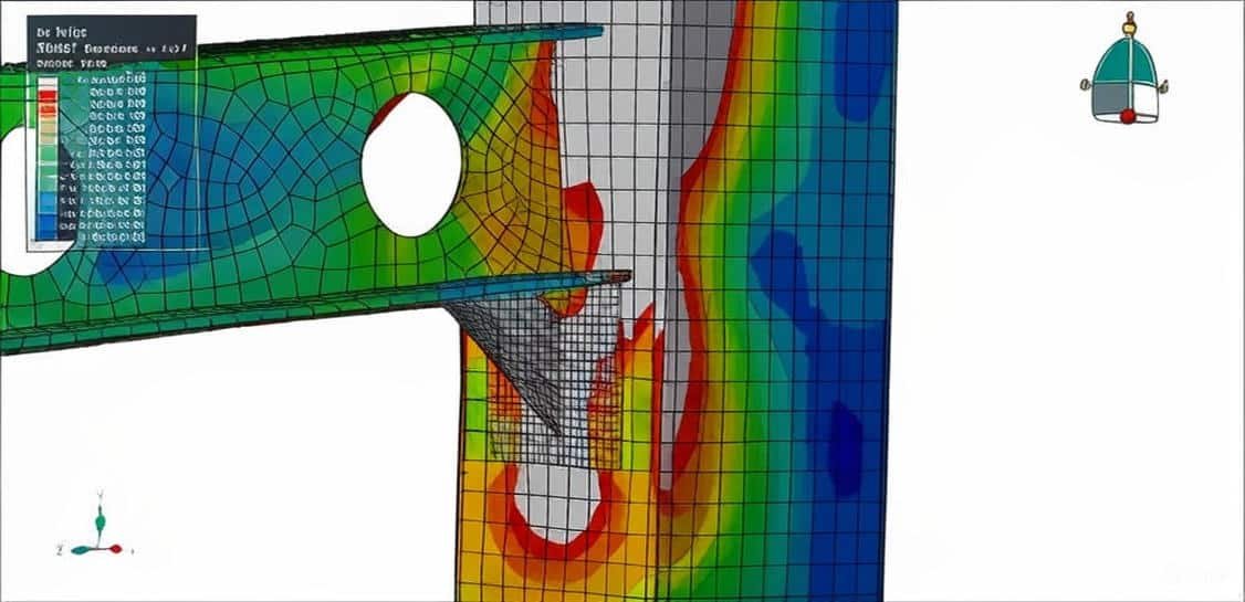
a) Finite Element Modeling (FEM)

  • Structures are discretized into elements (beam elements, shell elements, solid elements).
  • The governing equations are solved numerically.
  • Captures local stresses, stability, and nonlinearities.

b) Types of Analysis in Simulation

  1. Linear static analysis – small deformations, linear material.
  2. Nonlinear analysis – includes large deflections, material yielding, and contact.
  3. Buckling analysis – eigenvalue buckling (idealized), nonlinear buckling (realistic).
  4. Dynamic analysis – natural frequencies, vibration, seismic response.
  5. Fatigue and fracture simulation – important for bridges, cranes, and offshore structures.

4. Design Considerations in Simulation

  • Material properties: Yield strength, modulus of elasticity, strain-hardening, ductility.
  • Imperfections: Initial crookedness of columns, residual stresses from welding.
  • Load combinations: As per codes (Eurocode, AISC, IS, etc.).
  • Safety factors: Account for uncertainties in load, material, and modeling.

5. Applications

  • Buildings: Multi-story steel frames, composite slabs.
  • Bridges: Plate girders, cable-stayed, truss bridges.
  • Industrial plants: Pipe racks, cranes, offshore rigs.
  • Towers & masts: Lattice towers, communication towers.

 In short:
Steel structure analysis and simulation combine mechanics (theory) and computing (FEM, software) to model the response of beams, columns, frames, and connections under various loads. This allows engineers to design safe, efficient, and economical steel structures.

Course Content

Example 1: Dynamic tensile test simulation of a steel piece
In this lesson, the dynamic tensile test simulation of a steel piece is studied. A dynamic tensile test simulation of a steel piece is a computational study (often using finite element analysis, FEA) that models how steel behaves when subjected to high strain rates (fast loading conditions). Unlike a standard tensile test, which applies load slowly, the dynamic version replicates conditions such as impact, crash, or blast loading, where the material’s response can be very different. To model the failure behavior of the steel piece shear and ductile damage with evolution, isotropic plasticity with strain rate dependent has been used. The data is extracted from Abaqus documentation. This model can be analyzed in both static and dynamic terms. In this example, a dynamic explicit step to observe damage and failure has been used. To hasten the simulation mass scale as a time target is used. The back and front faces of the steel part are considered as rigid surfaces to which the load and displacement are assigned.

  • Abaqus files
  • Video
    00:00

Example 2: Analysis of the profiled steel deck composite slab system under bending load
In this section, the analysis of the profiled steel deck composite slab system under bending load is investigated. Composite slabs comprised of cold-formed profiled steel sheet and structural concrete topping are commonly used nowadays for the construction of buildings. In this system, steel deck serves as a permanent formwork for supporting the concrete and also acts as tensile reinforcement. The strength and performance of the composite slab is also influenced by other factors such as profile geometry, thickness of steel sheeting, concrete types/compressive strength, span, embossments/shear connectors, and steel-concrete interface shear bond controlling the composite action. By adopting suitable profile geometry with or without embossments, sufficient resistance against steel-concrete vertical separation and horizontal slippage can be achieved. The interfacial shear depends on several parameters, including the height, shape, and orientation of the embossment pattern and other shear connectors The concrete is modeled as a three-dimensional part, the steel deck as a shell part, bars as wire, and the connectors between the concrete and the deck are modeled as a beam element.

Example 3: Cyclic loading analysis of a steel column with stiffeners
In this case, the cyclic loading analysis of a steel column with stiffeners is done through a practical tutorial. The box column is modeled as a three-dimensional shell part, and the stiffener is modeled as a planar shell part. The stiffeners are used at the end of the column as a weld zone the fortify it, and the stiffeners should change the damage zone at the end to another place. Normally, kinematic or combined plasticity is used to model cyclic behavior because they have a variable yield surface, but in this simulation, the goal is to find the damage and failure location, so isotropic plasticity with ductile damage criterion to achieve it has been used. The ductile damage criterion can predict the damage zone under cyclic loading.The general static step was used. The boundary for the end of the column and the bottom edges of the stiffeners are assumed as a weld zone, so the fixed boundary condition is used for them. The cyclic loading with a specific protocol to define the load amplitude is used. The mesh has a good effect on the accuracy. The result shows the failed location or damaged zone moved from the end of the column to the upper part because of the stiffeners' effect.

Example 4: Simulation of the bolt failure under axial load in the beam-column joint
In this lesson, the simulation of the bolt failure under axial load in the beam-column joint is studied. The bolts, steel beam, and column are modeled as three-dimensional parts. The steel structure is an assemblage of different members, such as beams, columns, and plates, which need to be fastened or connected. The basic goal of connection design is to produce a joint that is safe, economical, and simple. It is also important to standardize the connections in a structure and to detail it in such a way that it allows sufficient clearance and adjustment to accommodate any lack of fit, resists corrosion, is easy to maintain, and provides a reasonable appearance. Because of the bolt or column failure, the steel is modeled as an elastic-plastic material with ductile and shear damage criteria to observe damage and failure on the parts. The dynamic explicit step is appropriate for this type of analysis because of the large deformation that can’t be done with standard analysis with the static solver. The surface-to-surface interaction among all parts is considered. The friction coefficient and hard contact property are assigned as the contact property. The fixed boundary condition for the end of the column and displacement as a load for the beam is assigned with the smooth step amplitude. All parts need to have a proper mesh, and to achieve it, they need to use many partitions in all parts to make a good mesh.

Example 5: Analysis of the steel beam-column connection with steel angle under cyclic loading
In this section, the analysis of the steel beam-column connection with steel angle under cyclic loading is investigated. The beam and column are modeled as three-dimensional shell parts, and the steel angle is modeled as a three-dimensional shell part. The steel material is modeled as elastic-plastic with ductile damage parameters to model failure behavior under cyclic loading. The shell thickness should be in the correct direction to avoid interference. The general static step with some modification to avoid non-convergence error. The general contact algorithm with contact property as friction and hard contact is used. The contact between the steel angle and the column, the steel angle and the beam, is assumed as perfect contact because they are welded. The fixed boundary conditions for the end of the column and displacement based on the specific protocol are assigned.

Example 6: Modeling of the steel beam-column connection with the bolt-failure model
In this case, the modeling of the steel beam-column connection with the bolt is done through a comprehensive tutorial. The beam with endplate is modeled as a three-dimensional solid part, the column is modeled as a three-dimensional solid part, and the ten bolts are modeled as three-dimensional solid parts. The steel material for the bolt is modeled as elastic-plastic behavior that depends on the strain rate, ductile damage with evolution, and shear damage with evolution to predict damage and failure in the bolt. The steel material for the column and for the beam is modeled as elastic-plastic with a ductile damage criterion. The dynamic explicit procedure is used to model large deformation and failure analysis in this simulation. All interactions, like a bolt with a beam or a bolt with columns, are assumed as the surface-to-surface contact with contact property behavior as a friction coefficient and normal contact.

Example 7: Analysis of the composite column (steel beam and concrete) under cyclic loading
In this lesson, the analysis of the composite column (steel beam and concrete) under cyclic loading is studied. The steel beam and the concrete parts are modeled as three-dimensional solid parts. The steel material is used for the steel beam as an elastic-plastic material with a ductile damage criterion to consider damage and failure during cyclic loading. The concrete is modeled as an elastic material with concrete damaged plasticity(CDP) to predict tensile and compressive damage. The general static step was used with ideal or perfect contact between the steel beam and concrete column surfaces. The fixed boundary condition for the bottom side of the composite column and displacement with tabular amplitude to assign the loading protocol for the top side is selected.

Example 8: Cyclic loading modeling of a steel beam column with a steel angle and gusset
In this section, the cyclic loading modeling of a steel beam column with a steel angle and gusset is investigated. The steel beam and box column are modeled as a three-dimensional shell part. The steel angle and gusset are modeled as a three-dimensional solid part. For all parts, steel material with elastic-plastic behavior and ductile damage criterion to predict the damaged zone is used. The cyclic loading causes failure and damage, especially at the joint zone, and that damage criterion can be considered in a good way. The general static step with a specific time period is selected. The contact between the steel angle and the beam, the steel angle and the column, is assumed as a perfect contact, like a weld joint. The fixed boundary condition is assigned to the top and bottom edges of the column, and displacement with an amplitude as a protocol is assigned to the beam.

Example 9: Cyclic loading analysis of a steel beam-column structure reinforced with CFRP
In this case, the cyclic loading analysis of a steel beam-column structure reinforced with CFRP in Abaqus software is done through a comprehensive tutorial. The steel beam and column are modeled as a three-dimensional shell part. The CFRP plates are modeled as a planar shell part. To model steel behavior under cyclic loading, the combined plasticity was used. This material model can predict the behavior of the material at each cycle. To define CFRP material, engineering constants of elasticity with Hashin’s damage criterion were used. The general static step with some changes in the convergence model has been implied. The perfect or ideal contact between the steel beam and steel column, steel beam, and CFRP sheets is used. The fixed boundary condition is used at the top and bottom ends of the steel column, and displacement with an amplitude as a loading protocol is assigned to the end of the steel beam.

Example 10: Analysis of the flexural behavior of a steel beam reinforced with CFRP
In this lesson, the analysis of the flexural behavior of a steel beam reinforced with CFRP is studied. The steel beam and CFRP sheet are modeled as three-dimensional shell parts. The rigid bodies are modeled as a discrete rigid body. Fiber-reinforced polymer (FRP) materials are composite materials that contain an epoxy matrix and fiber polymer. These FRP materials are being widely used as alternative materials for the rehabilitation and strengthening of concrete structures. The beneficial characteristics of FRP materials are a high strength-to-weight ratio, corrosion resistance, and high fatigue resistance. Common FRP composite materials used in rehabilitation and strengthening are Glass FRP (GFRP), Carbon FRP (CFRP), and Aramid FRP (AFRP). Several studies have been conducted on strengthening and rehabilitation of steel beams using CFRP composite materials. The major drawbacks of using CFRP for the rehabilitation and strengthening of a steel structure are its brittle failure modes and the possibility of galvanic corrosion. The steel material with elastic-plastic behavior, coupled with ductile damage criterion for the beam and elastic data as an engineering constant, coupled with Hashin’s damage criterion for the CFRP. These material models can predict the damage during the static stimulation and bending load. The general static stimulation with some changes in the convergence model is used. The surface-to-surface contact with the contact property is used among rigid parts with a steel beam and CFRP. The perfect contact is assumed between the steel beam and CFRP. The fixed boundary conditions are assigned to the bottom rigid bodies

Example 11: Simulation of the bolt shear failure of two steel plate connections
In this section, the simulation of the bolt shear failure of two steel plate connections is investigated. The steel plates are modeled as a three-dimensional solid part. The bolts with different sizes are modeled as a three-dimensional solid part. The steel material with elastic-plastic behavior is used. The ductile and shear damage criterion to predict the damaged zone and failure is used. The ductile criterion is a phenomenological model for predicting the onset of damage due to nucleation, growth, and coalescence of voids. The shear criterion is a phenomenological model for predicting the onset of damage due to shear band localization. The dynamic explicit step was used to model the dynamic load as tension at the end of the upper plate. The surface-to-surface contact with the contact property is used among all interaction domains. The fixed boundary condition is used for the end of the bottom steel plate, and displacement with a smooth amplitude to the end of the upper plate.

Example 12: Modeling of the three-point bending of a steel box beam filled with aluminum foam
In this case, the modeling of the three-point bending of a steel box beam filled with aluminum foam is done in Abaqus software. The steel box beam is modeled as a three-dimensional shell part. The aluminum foam is modeled as a three-dimensional solid part. The shell rigid body is created as a force body and boundary zone. Metal foam structures, due to their impact absorbing properties, could be considered as passive safety systems in transportation, which still have a great potential for development as a way to reduce deaths and injuries, which is also associated with the economic costs and social impacts associated with this problem. On the other hand, from an environmental standpoint, the use of advanced composite materials to this end can also represent an optimized level of energy efficiency. The impact energy absorption, with the use of a well-designed lightweight protection system, is directly related to the thermal efficiency and consumption of the engines, thus leading to a lower level of greenhouse gases sent to the atmosphere. For the steel box beam, the elastic-plastic material model with ductile damage criterion to predict damage initiation under bending is used. The aluminum foam is modeled as an elastic material with Crushable foam plasticity, which is available in Abaqus CAE. The general static step is appropriate for this type of analysis. The surface-to-surface contact algorithm with contact property is used to model interactions between rigid bodies and a steel box. The perfect contact is assumed between the steel box surfaces and the aluminum foam.

Example 13: Cyclic loading analysis of a steel pipe
In this lesson, the cyclic loading analysis of a steel pipe in Abaqus software is studied. A cyclic loading analysis of a steel pipe simulation is a computational study (often with finite element analysis, FEA) used to evaluate how a steel pipe behaves when subjected to repeated loading and unloading cycles (instead of a single static load). This mimics real conditions like oil & gas pipelines under pressure fluctuations, seismic loads, or vibration in structural systems. The pipe was modeled as a 3D pipe with steel material. For this type of analysis, we need to define a specific plasticity, such as Combined plasticity with cyclic hardening.

Example 14: Simulation of the steel beam damage under cyclic loading
In this section, the simulation of the steel beam damage under cyclic loading is investigated. Under cyclic loading conditions such as those introduced by earthquake ground motions, the local buckling is initiated in the compression flange. However, it disappears and reappears in subsequent cycles. The beam is modeled as a three-dimensional shell part. The linear elastic, isotropic plastic material model with a damage parameter to investigate damage distribution has been used. A general static step is appropriate for this type of analysis. The cycle load is assigned as a protocol to the tip of the beam. The mesh quality can increase the accuracy of this simulation.

Example 15: Analysis of the composite plate connection with a steel bolt under tension load
In this case, the analysis of the composite plate connection with a steel bolt under tension load is done. The two composite plates are modeled as three-dimensional solid parts. The steel bolt is modeled as a three-dimensional solid part. Because of the symmetry, half of the model is used to reduce the simulation time. Steel material with elastic-plastic behavior is used for the bolt. The ductile damage criterion to predict damage and failure of the bolt under tension load is implied. To model a composite material, epoxy-glass is used. The lamina elastic type with failure stress is selected. To predict damage in the composite layers, Hashin’s damage criterion with damage evolution is considered. The continuum shell section with four layers is selected for the two composite parts. The dynamic explicit procedure is selected to model the dynamic tension on the plates. The general contact algorithm with contact property is assumed among all parts in the contact domain. The symmetry boundary condition is assigned to the symmetry surfaces.

Example 16: Cyclic loading analysis of the steel beam-column structure and damage investigation
In this lesson, the cyclic loading analysis of the steel beam-column structure in Abaqus software is studied. The beam is modeled as a three-dimensional shell part, and two steel columns are modeled as three-dimensional shell parts. To model steel beams and columns under cyclic loading, elastic-isotropic plasticity coupled with a ductile damage criterion to predict damage during the simulation is used. The kinematic or combined plasticity can be used, but to predict damage, the isotropic plasticity and ductile damage can yield a better result. The general static step is appropriate for this type of analysis, and to avoid early non-convergence, some changes are made in the convergence model. The perfect or ideal contact is used between the beam and the columns. The general contact algorithm is selected to consider some regions that have interference during the simulation. The fixed boundary condition is assigned to the bottom nodes of the column.

Example 17: Dynamic failure behavior of steel beam-to-column bolted connections
In this section, the dynamic failure behavior of steel beam-to-column bolted connections is investigated. Stainless steel displays numerous desirable properties, which motivated many researchers to investigate its use in structural applications. Despite having a comparatively high initial cost, its excellent corrosion resistance, outstanding durability, superior response to elevated temperatures, considerable adaptability, ease of maintenance, and attractive appearance can enable it to be a more effective alternative to carbon steel. Most of the studies in the area of stainless steel structures concentrated on the structural performance of separate members, while the response of stainless steel connections (especially beam-to-column ones) still has not been well-researched. All parts, steel beam, column, steel angle, and bolt, are modeled as three-dimensional solid parts.

Example 18: Analysis of the dynamic bolt failure (bolt and steel plate joint)
In this case, the analysis of the dynamic bolt failure (bolt and steel plate joint) in Abaqus software is done. The upper and bottom steel plates are modeled as three-dimensional solid parts. The bolts are modeled as three-dimensional solid parts. Two main mechanisms can cause the fracture of a ductile metal: ductile fracture due to the nucleation, growth, and coalescence of voids; and shear fracture due to shear band localization. Based on phenomenological observations, these two mechanisms call for different forms of the criteria for the onset of damage. The ductile criterion is a phenomenological model for predicting the onset of damage due to nucleation, growth, and coalescence of voids. The shear criterion is a phenomenological model for predicting the onset of damage due to shear band localization. To observe the failure and damage, those criteria were used. The dynamic explicit step with a mass-scale technique is used to model the dynamic failure of the bolts. The surface-to-surface interaction with interaction properties like friction is considered.

Example 19: Simulation of the steel bolted double-angle connections under dynamic load
In this lesson, the simulation of the steel bolted double-angle connections under dynamic load is studied. The beam and column are modeled as a three-dimensional solid part. The bolts are modeled as a three-dimensional solid part. Connections have a crucial role in maintaining the overall stability of steel structures by providing continuity of load paths between structural elements. The steel grade fourteen with the elastic-plastic material model is used for all parts. To predict damage and failure in the bolts and beam, the ductile damage criterion is considered. In this way, the damage can be observed after the simulation. The dynamic explicit step is appropriate for this type of analysis. The mass scale technique to reduce simulation time and ensure stability in the model is used. The surface-to-surface contact with the contact property to define all contacts is implemented. The rough property is considered for the bolt connections.

Example 20: Analysis of tilted angle shear connectors in steel-concrete composite systems
In this section, the analysis of tilted angle shear connectors in steel-concrete composite systems is investigated. The concrete block is modeled as a three-dimensional solid part. The steel beam and steel angle connector are modeled as three-dimensional solid parts. Two rigid bodies are used as the boundary location and the hydraulic jack. Shear connectors are an important part of the design of composite beams. An effective connector provides for adequate shear strength for full composite action between the steel beam and concrete. In addition, its ductile behavior can alarm of imminent collapse. The ease of construction and economical aspects are also of concern. The search for new connectors that satisfy these criteria continues, and innovative developments appear routinely. Nowadays, several types of connectors are available, such as stud, Perfobond, channel, and angle connectors. The angle shear connector provides for shear strength through one leg and resistance against uplift through another leg that acts as a flange. The Concrete Damaged Plasticity is used to define concrete block behavior. The model is a continuum, plasticity-based, damage model for concrete. It assumes that the two main failure mechanisms are tensile cracking and compressive crushing of the concrete material. The elastic-plastic material model is selected for the steel shear angle connector and beam. The dynamic explicit step instead of the general static one is selected to avoid convergence. The surface-to-surface contact is used to define contact between the steel beam and the concrete.

Example 21: Cyclic loading analysis of a steel beam embedded in a concrete block
In this case, the cyclic loading analysis of a steel beam embedded in a concrete block is done through a practical tutorial. The steel beam (or column) is modeled as a three-dimensional shell part. The concrete block is modeled as a three-dimensional solid part. Half of the steel beam is embedded inside the concrete block. To model the cyclic loading behavior of the materials, the proper material model should be selected. In this tutorial for the steel beam, kinematic and combined hardening can be used; these two models can calculate the yield surface changing during each cycle. The Concrete Damaged Plasticity is used to model the concrete behavior. The general step is appropriate for this type of analysis, and it needs some changes in the convergence model to overcome the non-convergence. Half of the beam is embedded inside the concrete by using an embedded constraint in the interaction.

Reviews

Student Ratings & Reviews

No Review Yet
No Review Yet
249,00 549,00
10 people watching this product now!

Material Includes

  • 1- Abaqus Files
  • 2- Documents
  • 3- Tutorial Videos

Audience

  • 1- Civil Engineering
  • 2- Structural Engineering
  • 3- Mechanical Engineering

Related  Products

See more

Want to receive push notifications for all major on-site activities?