Engineering Downloads

Let’s Learn and Collaborate

Engineering Downloads

Steel and Concrete Columns Package in Abaqus

289,00 579,00
289,00 579,00
21 people watching this product now!

Material Includes

  • 1- Abaqus Files+ Codes
  • 2- Documens
  • 3- Tutorial Videos

Audience

  • 1- Civil Engineering
  • 2- Structural Engineering
  • 3- Mechanical Engineering
  • 4- Other Engineering fields

What You Will Learn?

  • During this comprehensive and practical course, you'll learn all about steel and concrete columns, including RC columns, RC composite columns, steel columns, steel composite columns, steel strips, angles, gussets, spiral strips, CFRP-reinforced columns, seismic analysis, cyclic loading, air blasts, CEL explosions, compression, concrete-filled steel columns, steel beam–open leg columns, UHPC beam–column joints, bolted connections, welded connections, spiral CFRP strips, wide beam–column joints, column retrofitting, UHPFRC, SPH explosions, hysteresis analysis, and many material models such as CDP, JH2, ductile damage, and combined plasticity.

About Course

Introduction to Steel and Concrete Column Analysis and Simulation

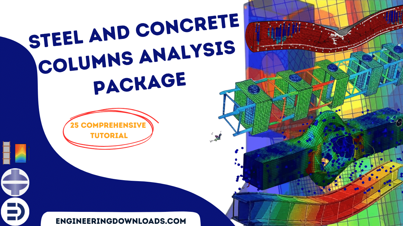
Columns are essential structural elements that primarily carry axial loads and may also resist bending, shear, and torsion. The performance of columns directly affects the safety, stability, and durability of buildings, bridges, and other civil engineering structures. Among the most common types are steel columns and reinforced concrete (RC) columns, each with distinct characteristics and design considerations.

This package includes 25 tutorials covering everything you need to master modeling and simulation

Steel Columns

Steel columns are widely used in high-rise buildings and industrial structures due to their high strength-to-weight ratio, ductility, and ease of fabrication. Their analysis often involves:

  • Elastic and plastic buckling under axial loads.
  • Lateral-torsional buckling in slender members.
  • Stress-strain modeling for steel, including nonlinear behavior.
  • Connections and boundary conditions that strongly influence performance.

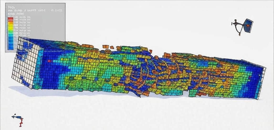
Simulation of steel columns typically includes finite element analysis (FEA) to study stress distribution, local and global buckling, and post-buckling behavior.

Concrete Columns

Concrete columns, usually reinforced with steel bars, are preferred for their compressive strength, fire resistance, and cost-effectiveness. Their analysis is more complex than steel because of the nonlinear, brittle behavior of concrete and the composite interaction with reinforcement. Key considerations include:

  • Confinement effects from transverse reinforcement.
  • Nonlinear stress-strain models for concrete and steel.
  • Cracking, crushing, and bond-slip phenomena.
  • Interaction diagrams (axial force vs. bending moment).

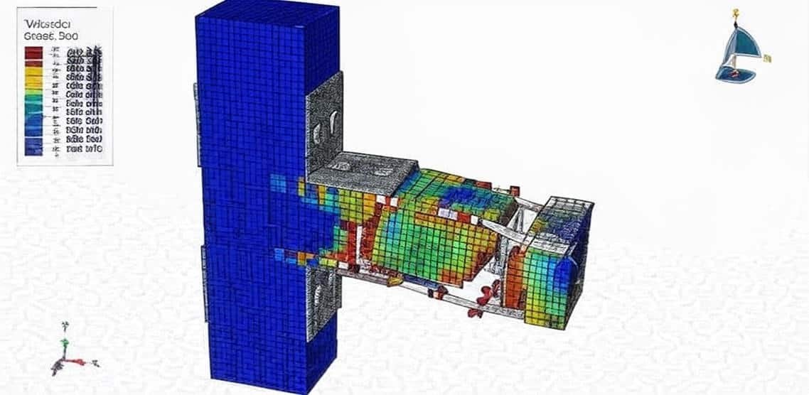
Simulations of concrete columns in software like Abaqus often rely on Concrete Damaged Plasticity (CDP) models or other advanced constitutive laws to capture material degradation, cracking, and failure modes.

Role of Simulation

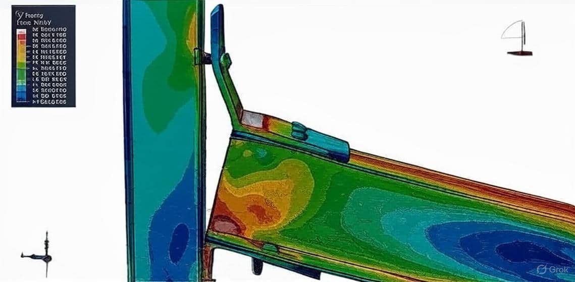
Finite element simulations (e.g., in Abaqus, ANSYS, SAP2000) provide powerful insights by:

  • Predicting load capacity and failure modes.
  • Assessing buckling resistance and ductility.
  • Optimizing reinforcement layouts and cross-sectional design.
  • Supporting performance-based design under seismic and dynamic loading.

By combining analytical methods (codes and hand calculations) with simulations, engineers can achieve safer, more economical, and reliable designs for steel and concrete columns.

Course Content

Example-1: Air blast analysis of an RC column with a spiral strip and a steel tube cover
In this lesson, the air blast analysis of an RC column with a spiral strip and a steel tube cover is studied using Abaqus software. The concrete column is modeled as a three-dimensional solid part. The spiral strips and bars are modeled as a three-dimensional wire part. The steel tube as a cover is modeled as a three-dimensional shell part. The Johnson–Holmquist-II(JH-2) model is introduced as the constitutive model for concrete material in blasting. However, complicated and/or high-cost experiments need to be carried out to obtain the parameters of the JH-2 constitutive model. In this example, the Johnson-Houmquist model is implemented as an input file code for concrete to consider damage variables. The Johnson-Cook hardening and damage model is particularly suitable for high-strain-rate deformation, making it a suitable definition for steel materials. The dynamic explicit step is selected for this analysis. perform dynamic simulations when speed is important. Explicit dynamics account for quickly changing conditions or discontinuous events, such as free falls, high-speed impacts, and applied loads. The steel reinforcements are embedded inside the concrete column host. The perfect contact is assumed between the concrete column and the steel tube. The CONWEP blast method is selected to apply the blast load on the column.

  • Abaqus Files+ Codes
  • Document
  • Tutorial Video-1
    00:00
  • Tutorial Video-2
    00:26

Example-2: Analysis of the seismic behavior of the CFRP-strengthened seismic-composite steel-concrete frame column
In this section, the analysis of the seismic behavior of the CFRP-strengthened seismic-composite steel-concrete frame column is investigated. The concrete and steel columns are modeled as three-dimensional solid parts. The steel reinforcements are modeled as wire parts. The CFRP box is modeled as a shell part. The frame column structure is composed of sections of steel-reinforced concrete and has been widely used in super-high building structures and large-span structures due to its high load-carrying capacity, good seismic performance, and other advantages. In practical engineering, the carbon fiber sheet has received considerable attention due to its high strength, lightweight, high corrosion resistance, ease of fabrication, etc. This effective strengthening method using composite steel-concrete structures has become more and more widely used in the United States, Canada, Japan, and, recently, Europe. In China, the research and application of carbon fiber reinforced polymer (CFRP) for strengthening reinforced concrete structures began in 1997. In this study, cyclic loading tests were performed on composite steel-concrete columns to investigate the effect of the strengthening of seismic-damaged composite steel-concrete with CFRP on the performance of frame columns. The tests included horizontal load testing, horizontal displacement testing, and recording of the load-displacement hysteresis loops of the specimen.

Example-3: Strengthening of the RC columns incorporating different configurations of stainless-steel plates
In this case, the strengthening of the RC columns incorporating different configurations of stainless-steel plates is presented. The concrete column, steel plates, and rods are modeled as three-dimensional solid parts. The steel bar and strips are modeled as wire parts. Reinforced concrete (RC) structures can require strengthening and rehabilitation over their service life due to deterioration, changes in usage, or deficiencies in the original design. Fiber-reinforced polymer(FRP) composites are often used to repair and retrofit RC elements. Additional jacketing using the steel tube, known as concrete-filled steel tubular (CFST) columns, is also used. However, CFST columns often face issues with corrosion problems when exposed to harsh environments, whereas jacketing using FRP is very expensive. Due to its high strength, durability, and ductility, there is a growing interest in utilizing stainless steel for these applications. Stainless steel possesses beneficial properties, including high durability, corrosion resistance, and easy maintenance. However, the high cost of stainless steel has limited its widespread use as a structural material. Recent research has explored using stainless steel as part of composite members, such as concrete-filled stainless steel tubular columns, to take advantage of its properties while reducing costs. Experimental studies on short and slender concrete-filled stainless steel tubular columns under axial and axial-flexural loading have demonstrated good performance as structural members. Additional tests on steel-concrete composite columns with stainless steel confinement tubes have shown increases in load capacity owing to the confinement of the concrete. Concrete is a brittle material, and Abaqus considers many material models for that. The Concrete Damaged Plasticity is a good approach to consider compression and tension damage. The elastic-plastic model is considered for all steel parts. The general static step is selected with some changes in the convergence model. Proper interactions and constraints are used to define the interaction among all parts.

Example-4: CEL explosion modeling near a composite RC column with an X-shaped steel core
In this lesson, the CEL explosion modeling near a composite RC column with an X-shaped steel core is studied. The concrete and steel X-shaped columns are modeled as three-dimensional solid parts. The steel reinforcements are modeled as wire parts, and the domain that contains the explosive charge is modeled as an Eulerian part. The Jones-Wilkins-Lee material model was selected to model the explosive material. The Jones-Wilkins-Lee (or JWL) equation of state models the pressure generated by releasing chemical energy in an explosive. This model is implemented in a form referred to as a programmed burn, which means that the reaction and initiation of the explosive are not determined by shock in the material. Instead, the initiation time is determined by a geometric construction using the detonation wave speed and the distance of the material point from the detonation points. To model concrete behavior under severe load, Abaqus recommends some material models; here, the Concrete Damaged Plasticity model with strain damage behavior is selected. The model is a continuum, plasticity-based, damage model for concrete. It assumes that the two main failure mechanisms are tensile cracking and compressive crushing of the concrete material. To model the X-shaped steel core and reinforcements, the Johnson-Cook hardening and dynamic damage are selected. Dynamic explicit steps and general contact capability to consider all contacts in the contact domain are considered.

Example-5: Cyclic Test Analysis of a Concrete-Filled Steel Column
In this section, the Cyclic Test Analysis of a Concrete-Filled Steel Column is done through a comprehensive tutorial. The steel box column, ribs, and stiffener plates are modeled as three-dimensional shell parts. The two concrete blocks are modeled as three-dimensional solid parts. Concrete-damaged plasticity is selected to model concrete behavior under cyclic loading. The concrete damage plasticity material model represents a constitutive model based on a combination of the theory of plasticity and the theory of damage mechanics. This material model is often used in solving geotechnical problems due to its realistic description of the mechanical behavior of concrete material. The elastic-plastic model is considered for the steel material. The analysis is done in two stages. In the first step, the axial load is applied through a static step, and in the second step, the cyclic load is applied to the column. The weld contact model is considered among all steel parts and surface-to-surface contact among the other parts.

Example-6: Analysis of a steel beam-open leg column joints under cyclic loading
In this case, the analysis of a steel beam-open leg column joints under cyclic loading is presented. Steel structure columns are vertical members in a steel structure that support the load-bearing beams and other structural elements above. They are typically made of high-strength steel and come in various shapes and sizes to meet the specific needs of the building or structure. The steel beam and column are modeled as three-dimensional parts; all the stiffener plates are modeled as three-dimensional parts. The steel column is the structural component that bears the main vertical load in the steel structure building. Based on their cross-sectional shape, they are classified into solid-web and lattice columns. The solid web column has an overall cross-section, with commonly used shapes being I-beams, typically made of hot-rolled H-beams, I-beams, or welded H-beams. Solid web columns are generally used in light steel structure buildings. The proper material model is used for all members to consider the cyclic loading effect. The general static step is appropriate for this type of analysis. In each cycle, a specific load is applied to the steel beam by using a certain displacement through an amplitude.

Example-7: Modeling of the UHPC beam-column joint reinforced with steel angle and bolts
In this lesson, the modeling of the UHPC beam-column joint reinforced with steel angle and bolts is studied. The Ulta-High-Performance-Concrete beam-column joint is modeled as a three-dimensional solid part. The steel bar and strips are modeled as three-dimensional wire parts. The steel angle, plates, and bolts are modeled as three-dimensional solid parts. Reinforced concrete (RC) moment-resisting frame structures are the most common building type worldwide, including Bangladesh. A huge amount of concrete is produced each year worldwide, and the demand for concrete is increasing. The constituents of concrete are available in several variations, especially for coarse aggregates. With the increasing demand for RC construction, the safety of such structures from seismic or dynamic load events is becoming more critical for the civil engineering community. To model the UHPC joint under normal and axial loading, the Concrete Damage Plasticity is selected. The concrete damage plasticity material model represents a constitutive model that is based on a combination of the theory of plasticity and the theory of damage mechanics. This material model is often used in solving geotechnical problems due to its realistic description of the mechanical behavior of concrete material. To model steel behavior for all metal members, the elastic-plastic behavior with damage properties is considered.

Example-8: Load capacity analysis of a composite joint between a reinforced concrete column and a steel beam
In this section, the load capacity analysis of a composite joint between a reinforced concrete column and a steel beam is investigated. The concrete column is modeled as a three-dimensional solid part. The steel beam and column are modeled as three-dimensional solid parts. The steel bar and strip are modeled as wire parts. The reinforced concrete column and steel beam (RCS) frames consist of reinforced concrete (RC) columns and steel (S) beams. This type of structure has several advantages over traditional RC frames or steel frames, including lower cost and structure weight reduction. RC columns offer superior damping properties to a structure, especially in tall buildings. Indeed, using RC instead of structural steel as columns can result in substantial savings in material cost and an increase in the structural damping and lateral stiffness of the building. The energy dissipation capacity can accordingly be provided through steel beams. In addition, steel floor systems are significantly lighter compared to RC floor systems, leading to substantial reductions in the weight of the building, foundation costs, and inertial forces. To eWhen actively applying RCS frames in a real structure, it is necessary to study the composite connection between steel beams and reinforced concrete columns. Extensive studies have been conducted to study the basic force transfer mechanisms in connection regions and the performance of various joint configurations that enhance the connection performance under seismic excitations. The American Society of Civil Engineers. To model concrete behavior under axial or cyclic loading, the Concrete Damaged Plasticity is selected. The Concrete damage plasticity material model represents a constitutive model that is based on a combination of the theory of plasticity and the theory of damage mechanics. This material model is often used in solving geotechnical problems due to its realistic description of the mechanical behavior of concrete material. The elastic-plastic model with damage behavior is considered for the steel members.

Example-9: Cyclic loading analysis of a steel beam-column joint with the welded steel angle
In this case, the cyclic loading analysis of a steel beam-column joint with the welded steel angle is presented. Box column, steel beam angles, and stiffeners are modeled as the three-dimensional solid part. If a structural steel member is subjected to a cyclically varying load of sufficient amplitude, it may fail after a certain number of load repetitions, even though the maximum load in a single cycle is much less than that required to cause yielding or fracture. Cyclic loading refers to the process in which stress or strain is applied to a material repeatedly over time, causing the material to experience alternating periods of loading and unloading. It is a key factor in the study of fatigue and failure in materials.. Under cyclic loading, the elastic deformation will be recovered in the process of unloading, but the irreversible deformation will remain. The irreversible deformation, growth trend, and accumulation of total fatigue are directly related to fatigue damage. To model steel material under cyclic load, Kinematic and Combined hardening can be used to consider the stress-strain diagram in each cycle. The analysis procedure would be the general static approach. To define weld joints, surface-to-surface interaction or constraints can be selected. The proper boundary with the cyclic load protocol is applied to the beam.

Example-10: Compression test analysis of an RC column with spiral CFRP
In this lesson, the compression test analysis of an RC column with spiral CFRP is studied. The concrete column is modeled as a three-dimensional solid part. The spiral CFRP is modeled as a three-dimensional solid part. The steel bar is modeled as a wire part. To model concrete behaviour, the Concrete Damaged Plasticity is used. The model is a continuum, plasticity-based, damage model for concrete. It assumes that the two main failure mechanisms are tensile cracking and compressive crushing of the concrete material. The concrete damaged plasticity model in Abaqus provides a general capability for modeling concrete and other quasi-brittle materials in all types of structures, and it is designed for applications in which concrete is subjected to monotonic, cyclic, and/or dynamic loading under low confining pressures. Two models of the column with fully damaged and without fully damaged are simulated. The elastic material as engineering constant data is considered for the spiral CFRP. The elastic-plastic material with ductile damage criterion is selected for the steel reinforcement. The dynamic explicit step is appropriate for this type of analysis. The CFRP and steel reinforcements are embedded inside the concrete column.

Example-11: Compression test of the CFRP composite spirals in a circular hollow UHPC column
In this section, the compression test of the CFRP composite spirals in a circular hollow UHPC column is investigated. The Ultra-High-Performance-Concrete column is modeled as a three-dimensional solid part. The spiral CFRP part is modeled as a solid part, and the longitudinal steel bar is modeled as a wire part. Hollow ultra-high-performace-concrete columns (UHPC) are preferred to be used for ground piles, utility poles, piers with medium–low height, and piers of tall bridges due to their higher resistance to axial loading and bending moments, superior structural efficiency, higher stiffness to mass and strength to mass ratios, lower self-weights, and economic designs as compared with the solid concrete columns. Recently, carbon fiber reinforced polymers (CFRPs) have been used as longitudinal and transverse reinforcements in hollow and solid concrete columns. The Concrete Damaged Plasticity is used to model a UHPC column under compression load. The CFRP spiral part is defined as an elastic member. The elastic-plastic model is selected for the steel bar. The dynamic explicit step with a specific time, and perfect contact between the rigid bodies and the column, is considered. The CFRP and steel bars are embedded inside the UHPC column.

Example-12: Analysis of the RC beam column joint reinforced with steel plates and rods under vertical load
In this case, the analysis of the RC beam column joint reinforced with steel plates and rods under vertical load is presented. The concrete beam-column is modeled as a three-dimensional solid part. The steel bar and strip are modeled as a three-dimensional wire part. The steel plates and rods are modeled as a three-dimensional solid part. Concrete is a very heterogeneous material that shows complex nonlinear mechanical behavior. In addition, it is very difficult to define damage in a concrete structure. In the analysis of concrete structures using the finite element method, material models are used for these purposes. An example of these material models is the concrete damage plasticity material model. This material model combines the yield theory of plasticity and the theory of damage mechanics in order to effectively analyze the concrete structure's behavior. Material parameters identification of the concrete damage plasticity material model is performed in this example. The concrete damaged plasticity can show the tension and compression damage of the beam column joint after loading. The steel material with elastic-plastic behaviour is considered for all steel reinforcement. To model the damage behaviour of the steel plates and rods, the ductile damage criterion is selected. Both dynamic and static steps can be used in this tutorial; to decrease the time of the simulation, a dynamic explicit step with the mass scale technique is used. The perfect contact, surface-to-surface contact with friction, and embedded region constraint are applied for all parts

Example-13: Seismic analysis of an RC exterior wide beam-column joint
In this lesson, the seismic analysis of an RC exterior wide beam-column joint is studied. The concrete beam and column are modeled as three-dimensional solid parts. The steel bars and strips are modeled as three-dimensional wire parts. Reinforced concrete (RC) structures with wide and shallow beams provide different advantages and needs from construction and architectural points of view. A wide beam system may reduce the amount of formwork through repetition, and then the construction cost can be greatly reduced, and the construction works can be simplified. Furthermore, a smaller story height can be achieved from a wide beam system due to shallow beam depths. The Concrete Damaged Plasticity(CDP) is used to define beam-column behavior under cyclic loading. The model is a continuum, plasticity-based, damage model for concrete. It assumes that the two main failure mechanisms are tensile cracking and compressive crushing of the concrete material. The elastic-plastic material data is selected for the steel reinforcements. The general static step with some changes on the convergence model is selected. The steel reinforcements are embedded inside the concrete beam-column system.

Example-14: Cyclic loading analysis of a composite column(UHPC-Steel Box)
In this section, the cyclic loading analysis of a composite column(UHPC-Steel Box) is investigated. The Ultra-High-Performance Concrete column is modeled as a three-dimensional solid part. The steel box cover is modeled as a three-dimensional shell part. The concrete-filled steel box has great potential to be used in the construction of bridges and buildings. Although concrete is the most universally used material in building, there are still some limitations to its use, such as low tensile strength and brittleness. Ultra-High Performance Concrete (UHPC), a cutting-edge concrete, may be able to overcome these concerns. The Concrete Damaged Plasticity model is used to define UHPC column behavior under cyclic loading. The model is a continuum, plasticity-based, damage model for concrete. It assumes that the two main failure mechanisms are tensile cracking and compressive crushing of the concrete material. To define steel box behavior, the elastic-plastic model with ductile damage criterion to consider the damage during the cyclic loading is used. The general static step with some changes in the convergence model to avoid early non-convergence is considered. Two types of interaction between the UHPC column and steel are assumed: First, the cohesive surface interaction, and second, the perfect contact. To define cohesive surface interaction, stiffness, damage, and fracture energy should be defined.

Example-15: Analysis of the retrofit Jute-Epoxy composite of the concrete column under dynamic compression
In this case, the analysis of the retrofit Jute-Epoxy composite of the concrete column under dynamic compression is presented. The concrete column is modeled as a three-dimensional solid part. The just-Epoxy part is modeled as a three-dimensional shell. A rigid body is used as the hydraulic jack. The Concrete Damaged Plasticity model is used to model concrete column behavior under compression load. The model is a continuum, plasticity-based, damage model for concrete. It assumes that the two main failure mechanisms are tensile cracking and compressive crushing of the concrete material. This model uses tensile and compressive stress-strain separately and can also predict tensile and compressive damage. The conventional shell with four different layers is used to model the Jute-Epoxy lamina. The elastic properties as an engineering constant are selected for the Jute-Epoxy. The dynamic explicit step with the mass scale technique to make a quasi-static situation. The general static step can also be used also but because of the non-convergence, it needs plenty of time to complete the simulation; on the other hand, the explicit step is much faster than the static one. The general contact capability with frictional behavior is selected. The perfect contact is assumed between Jute-Epoxy and the concrete column.

Example-16: Behavior of Beam-Column Joints Strengthened With UHPFRC under axial load
In this lesson, the Behavior of Beam-Column Joints Strengthened With UHPFRC under axial load is studied. The beam-column joint is modeled as a three-dimensional solid part. The UHPFRC parts are modeled as three-dimensional solids as reinforcement. The strips and bars are modeled as three-dimensional wire parts. The beam-column joint is modeled as a three-dimensional solid part. The UHPFRC parts are modeled as three-dimensional solids as reinforcement. The strips and bars are modeled as three-dimensional wire parts. The concrete material with the CDP material model is used to model the concrete beam-column joint under axial loading. The model is a continuum, plasticity-based, damage model for concrete. It assumes that the two main failure mechanisms are tensile cracking and compressive crushing of the concrete material. The steel material with elastic-plastic data is used to model strips and bars. The CDP model is also used to model UHPFRC during the analysis. The UHPFRC can be used at the joint areas to increase beam-column joint ductility and can improve the tensile stress capacity. The general static step with some changes in the convergence model to avoid early non-convergence. The ideal or perfect contact is used to model contact between the UHPFRC reinforcement and the beam-column joint. The embedded region is considered for the steel members inside the concrete host. The pressure load is applied to the top surface of the column, and the displacement to the end of the beam.

Example-17: Modeling of the SPH explosion inside the RC column with an outer steel box cover
In this section, the modeling of the SPH explosion inside the RC column with an outer steel box cover is investigated. The concrete and TNT are modeled as three-dimensional solid parts. The steel box is modeled as a three-dimensional shell part. The steel bars and strips are modeled as three-dimensional wire parts. To model the steel behavior of the box, bars, and strips, the elastic-plastic material model is used. To model the damage and failure during the detonation, the Johnson-Cook damage model with evolution is selected. The JC criterion can predict failure under severe loads like an explosion. The JWL equation of state is used to model TNT behavior. The Jones-Wilkins-Lee (or JWL) equation of state models the pressure generated by the release of chemical energy in an explosive. This model is implemented in a form referred to as a programmed burn, which means that the reaction and initiation of the explosive is not determined by shock in the material. Instead, the initiation time is determined by a geometric construction using the detonation wave speed and the distance of the material point from the detonation points. To model concrete behavior under severe pressure and dynamic load, Abaqus has some material models that are appropriate for this simulation. These material models are available through the subroutine or input file modification. The dynamic explicit step and general contact algorithm are implemented. The perfect contact is assumed between the steel box and the concrete. The embedded region constraints are selected for the bar and strips.

Example-18: Dynamic failure analysis of a steel beam-to-column bolted connection
In this case, the dynamic failure analysis of a steel beam-to-column bolted connection is presented. Stainless steel displays numerous desirable properties, which motivated many researchers to investigate its use in structural applications. Despite having a comparatively high initial cost, its excellent corrosion resistance, outstanding durability, superior response to elevated temperatures, considerable adaptability, ease of maintenance, and attractive appearance can enable it to be a more effective alternative to carbon steel. Most of the studies in the area of stainless steel structures concentrated on the structural performance of separate members, while the response of stainless steel connections (especially beam-to-column ones) still has not been well-researched. All parts, steel beam, column, steel angle, and bolt, are modeled as three-dimensional solid parts. The steel material with elastic-plastic behavior is used for all parts. To observe damage and failure, especially at the bolt contact zone, the ductile damage criterion is considered. The dynamic explicit step with a mass-scale technique is used. The mass scale option can make stability on the modelstable and reduce the time of the simulation. Among all parts, the surface-to-surface interaction with contact property is applied. The surface-to-surface contact offered by ABAQUS was employed for simulating the interactions between the non-welded parts of connections. “Hard” contact relationship was used for the normal interaction, to permit the complete transfer of compression forces and prohibit the tensile stresses from being transmitted across the interface.

Example-19: Cyclic loading analysis of a steel beam-double columns connection
In this lesson, the cyclic loading analysis of a steel beam-double columns connection is studied. The beam is modeled as a three-dimensional shell part, and two steel columns are modeled as three-dimensional shell parts. To model steel beam and columns under cyclic loading, elastic-isotropic plasticity coupled with a ductile damage criterion to predict damage during the simulation is used. The kinematic or combined plasticity can be used, but to predict damage, the isotropic plasticity and ductile damage can show better results. The general static step is appropriate for this type of analysis, and to avoid early non-convergence, some changes are made in the convergence model. The perfect or ideal contact is used between the beam and the columns. The general contact algorithm is selected to consider some regions that have interference during the simulation.

Example-20: Modeling of the CEL explosion near a steel column and concrete foundation in interaction with soil
In this section, the modeling of the CEL explosion near a steel column and concrete foundation in soil is investigated. The steel column and steel plate are modeled as a three-dimensional solid part. The TNT and soil are modeled as a three-dimensional part. The embedded beam inside the concrete is modeled as a wire part. The Eulerian part is modeled as a three-dimensional part. The steel material is used as an elastic-plastic material with ductile and shear-damaged data. The ductile criterion is a phenomenological model for predicting the onset of damage due to nucleation, growth, and coalescence of voids. The shear criterion is a phenomenological model for predicting the onset of damage due to shear band localization. For the TNT, the JWL equation of state is used. The Jones-Wilkens-Lee (or JWL) equation of state models the pressure generated by the release of chemical energy in an explosive. This model is implemented in a form referred to as a programmed burn, which means that the reaction and initiation of the explosive are not determined by shock in the material. Instead, the initiation time is determined by a geometric construction using the detonation wave speed and the distance of the material point from the detonation points. The soil material is modeled as elastic-plastic behavior. The dynamic explicit method is appropriate for this type of analysis.

Example-21: Analysis of the air blast explosion near a composite column(Concrete+Steel box and I-shape beam)
In this case, the analysis of the air blast explosion near a composite column (a concrete and steel box with an I-shape beam) is conducted through a comprehensive tutorial. The model contains three deformable parts. The outer steel box, serving as a cover, is modeled as a three-dimensional shell, the middle concrete is modeled as a three-dimensional solid part, and the internal steel beam is modeled as a three-dimensional solid part. To model steel behavior under the blast load, elastic-plastic data with a ductile damage criterion are used. The ductile damage criterion can predict the damage and failure of the steel part during the analysis. To model concrete behavior under the rapid load, Abaqus has many material models, such as Brittle Cracking, Concrete Damaged Plasticity… but in this simulation to observe the damage zone and its propagation, the material should be proper, so the input file or VUMAT subroutine can be useful. In this tutorial, concrete material data is used as an input file for Abaqus. The Abaqus explicit step is appropriate for this type of analysis. The contact between the concrete and steel parts is assumed to be a perfect or ideal contact. The surface-to-surface contact with contact property as tangential friction with shear stress limit can be used. The CONWEP method is used to model the explosion procedure.

Example-22: Cyclic loading simulation of a steel beam-column structure reinforced with CFRP
In this lesson, the cyclic loading simulation of a steel beam-column structure reinforced with CFRP is studied. The steel beam and column are modeled as a three-dimensional shell part. The CFRP plates are modeled as a planar shell part. To model steel behavior under cyclic loading, the combined plasticity was used. This material model can predict the behavior of the material at each cycle. To define CFRP material, engineering constants of elasticity with Hashin’s damage criterion are used. The general static step with some changes in the convergence model has been implied. The perfect or ideal contact between the steel beam and the steel column, steel beam, and CFRP sheets is used. The cyclic loading protocol is applied to the beam, and the effect of the CFRP on the Hysteresis diagram is considered.

Example-23: Seismic analysis of a steel beam-column joint with the steel angle and gusset
In this section, the seismic analysis of a steel beam-column joint with the steel angle and gusset is investigated. The steel beam and box column are modeled as a three-dimensional shell part. The steel angle and gusset are modeled as a three-dimensional solid part. For all parts, steel material with elastic-plastic behavior and ductile damage criterion to predict the damaged zone is used. The cyclic loading causes failure and damage, especially at the joint zone, and that damage criterion can be considered in a good way. The general static step with a specific time period is selected. The contact between the steel angle and the beam, the steel angle and the column, is assumed as a perfect contact, like a weld joint. The fixed boundary condition is assigned to the top and bottom edges of the column, and a displacement with an amplitude as a protocol is assigned to the beam.After the simulation, the effect of the steel angle with the gusset will be clear because of its stiffness; less damage happened at the bottom side of the beam, on the other hand, huge damage happened at the top surface of the beam without the steel angle.

Example-24: Analysis of the bolted steel beam-column connection under axial load
In this case, the analysis of the bolted steel beam-column connection under axial load is presented. The beam with endplate is modeled as a three-dimensional solid part, the column is modeled as a three-dimensional solid part, and the ten bolts are modeled as three-dimensional solid parts. The steel material for the bolt is modeled as elastic-plastic behavior that depends on the strain rate, ductile damage with evolution, and shear damage with evolution to predict damage and failure in the bolt. The steel material for the column and for the beam is modeled as elastic-plastic with a ductile damage criterion. The dynamic explicit procedure is used to model large deformation and failure analysis in this simulation. All interactions, like a bolt with a beam or a bolt with columns, are assumed as the surface-to-surface contact with contact property behavior as a friction coefficient and normal contact. After the analysis, the beam at the connection zone failed because of the huge axial load.

Example-25: Modeling of the steel-concrete composite column under vertical and horizontal load
In this section, the modeling of the steel-concrete composite column under vertical and horizontal loads is investigated. Steel-concrete composite columns are new composite members. They are widely used due to their high load-bearing capacity, full usage of materials, high stiffness and ductility, and large energy absorption capacity, as pointed out by researchers. Combining reinforced concrete (RC) and structural steel sections provides several advantages over traditional reinforced concrete and steel members. The concrete provides fire resistance to the steel section and restrains the steel member from buckling . Applying steel-concrete composite columns has a beneficial impact on the course and values of concrete strains in relation to reinforced concrete columns. However, SRC columns require longitudinal and transverse reinforcement to prevent the concrete from spalling while being subjected to axial load, fire, or an earthquake The concrete column and steel beam, as the core, are modeled as a three-dimensional part, the bar as a wire, and the pusher plate as rigid. Elastic plastic material with ductile damage criterion is used for steel members, and the Concrete Damage Plasticity or CDP model is used for concrete columns. In this tutorial, general static and dynamic explicit procedures are used separately, and the results the compared at the end of the simulations. The contact between the concrete and the steel beam is assumed to be a perfect contact, and bars are embedded in the concrete host. Vertical concentrated force is applied to the top surface of the column, and pressure load is applied to the side surface of the concrete.

Reviews

No Review Yet
No Review Yet
289,00 579,00
21 people watching this product now!

Material Includes

  • 1- Abaqus Files+ Codes
  • 2- Documens
  • 3- Tutorial Videos

Audience

  • 1- Civil Engineering
  • 2- Structural Engineering
  • 3- Mechanical Engineering
  • 4- Other Engineering fields

Related  Products

See more

Want to receive push notifications for all major on-site activities?