Engineering Downloads

Let’s Learn and Collaborate

Engineering Downloads

Steel and Concrete Beam Analysis Package

277,00 549,00
277,00 549,00
11 people watching this product now!

Material Includes

  • 1- Abaqus Files
  • 2- Documents
  • 3- Tutorial Videos

Audience

  • 1- Mechanical Engineering
  • 2- Civil Engineering
  • 3- Structural Engineering

What You Will Learn?

  • In this comprehensive and practical package, you’ll learn all about concrete and steel beams, including topics such as fire resistance, RC concrete slabs, bending, shear studs, composite beams, UHPC, UHPFRC, NSC, beam-column joints, steel angles, bolts, air blasts, spiral GFRP reinforcement, cyclic loading analysis, RC exterior wide beam-column joints, repeated impact, four- and five-point bending, honeycomb steel beams, beam failures, beam-to-column bolted connections, and many other subjects.

About Course

Introduction to Steel and Concrete Beam Analysis and Simulation

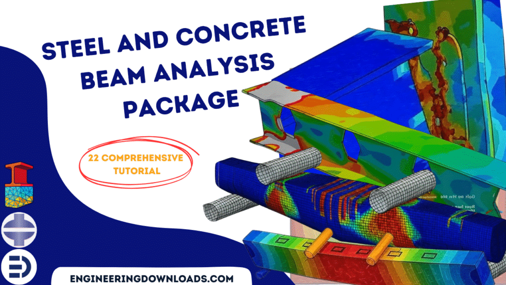
Steel and concrete beams are fundamental structural elements in civil and structural engineering, widely used in bridges, buildings, and industrial structures. Their analysis is crucial to ensure safety, serviceability, and cost efficiency in construction. Since beams primarily resist bending, shear, and axial forces, engineers must accurately predict their mechanical behavior under different loading and boundary conditions.

This course includes 22 tutorials that cover all about concrete and steel beam modeling and simulation in Abaqus software. 

Steel Beams

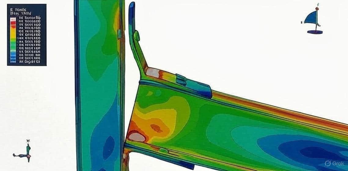
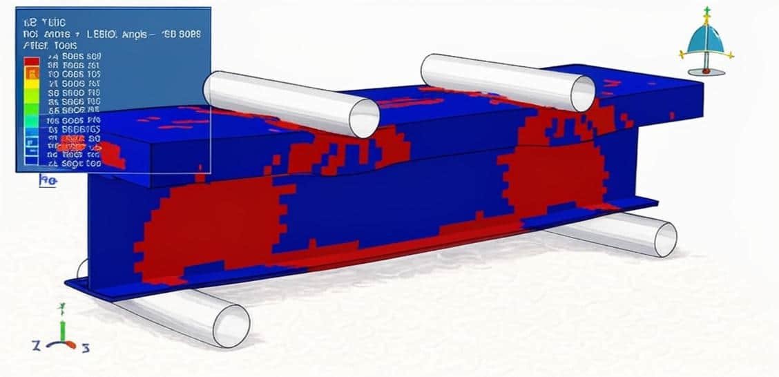
Steel beams are preferred for their high strength-to-weight ratio, ductility, and ease of fabrication. Their behavior can often be described using linear elastic models, but nonlinear effects such as plastic deformation, buckling, and fatigue must also be considered in advanced simulations.

Concrete Beams

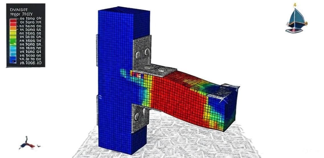
Concrete beams, particularly reinforced concrete (RC) beams, rely on the combination of concrete’s compressive strength and steel reinforcement’s tensile capacity. Their analysis is more complex due to nonlinear stress–strain relationships, cracking, creep, and shrinkage. Simulation helps capture these effects accurately, especially for ultimate load capacity and serviceability checks.

Simulation Approaches

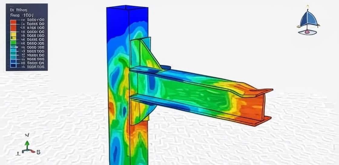
Modern structural analysis software, such as Abaqus, ANSYS, and SAP2000, provides advanced tools for modeling and simulating steel and concrete beams:

  1. Finite Element Analysis (FEA):

    • Beams are discretized into finite elements (1D, 2D, or 3D).
    • Governing equations are solved numerically for stresses, strains, and deflections.
  2. Steel Beam Simulation:

    • Linear and nonlinear elasticity models.
    • Plasticity, local and global buckling.
    • Fatigue and fracture mechanics.
  3. Concrete Beam Simulation:

    • Material models accounting for cracking, crushing, creep, and shrinkage.
    • Reinforcement modeling (bond-slip between steel and concrete).
    • Load-deflection curves and ultimate failure modes.

Applications

  • Structural design optimization (economical cross-section selection).
  • Safety verification under static and dynamic loads.
  • Performance assessment of composite steel–concrete structures.
  • Failure prediction and retrofitting of existing structures.

In summary, simulation of steel and concrete beams enables engineers to go beyond traditional hand calculations, providing deeper insights into structural performance under real-world conditions. It supports safer, more efficient, and more innovative designs.

Course Content

Example-1: Fire and bending analysis of a composite beam (RC concrete slab+ steel beam)
In this case, the fire and bending analysis of a composite beam (RC concrete slab + steel beam) is investigated. The concrete slab is modeled as a three-dimensional solid part. The steel reinforcements are modeled as wire parts. The steel beam is modeled as a three-dimensional solid part, and a rigid body to apply a load is also used. Steel–concrete composite beams are often employed in office and industrial buildings or bridges and viaducts for fast and economic erection. Most usually, they comprise a steel girder and a reinforced concrete slab interconnected by shear connectors (fasteners). The number of shear connectors largely determines whether the composite cross-section behaves as compact or partially connected. In any case, the deformation of the beam causes some relative tangential displacement (slip) between the steel girder and the concrete slab. While usually being very small, slip can have a substantial effect on the overall ductility of the beam, which indicates that it should be taken into account in the analysis. The issue that plays an important role in the concrete and composite steel–concrete beams' response due to fire is the effect of moisture transport on the temperature and stress distribution histories in the concrete part of the cross-section. In the composite beam context discussed here, we are particularly interested in assessing these effects quantitatively. To model the fire analysis, first fire simulation through a heat transfer model is considered, and the nodal temperatures are extracted from the model as an input for the structural model. In the second stage, the static model is performed bending is applied to the top surface of the concrete slab, and the fire results are implied as the initial situation

  • Abaqus Files
  • Document
  • Tutorial Video
    38:17

Example-2: Shear stud distribution analysis on the load capacity of the steel-concrete composite beam
In this case, the shear stud distribution analysis on the load capacity of the steel-concrete composite beam is studied. The concrete slab, steel beam, and studs are modeled as three-dimensional solid parts. The steel reinforcements are modeled as wire parts. Recently, there has been a wide use of steel–concrete composite beams in buildings and bridge construction. Their advantages include high bending capacity and stiffness due to the benefits of composite action and high speed of fabrication and construction. Despite an improved understanding of their behavior, several composite structures failed to satisfy their structural and functional demands due to stud shearing or concrete crushing as a direct result of fatigue. The Concrete Damaged Plasticity model is selected to model concrete material under bending load. The model is a continuum, plasticity-based, damage model for concrete. It assumes that the two main failure mechanisms are tensile cracking and compressive crushing of the concrete material. The elastic-plastic model is selected for all the steel members, like steel beams, studs, and reinforcements. The general static step is appropriate for this analysis; in the interaction, all contacts and constraints are assigned to all parts.

Example-3: Analysis of the defected RC beam with sustainable aluminum boxes incorporating ultra-high-performance concrete
In this section, the analysis of the defected RC beam with sustainable aluminum boxes incorporating ultra-high-performance concrete is investigated. The concrete beam, UHPC members, and aluminum boxes are modeled as three-dimensional solid parts. The steel reinforcements are modeled as wire parts. Building codes require shear reinforcement in concrete beams to prevent catastrophic and sudden shear failure. However, many existing beams might lack adequate reinforcement for various reasons, leaving them susceptible to this brittle failure mode. Consequently, repair or strengthening becomes crucial to restore their structural integrity and safety. RC beams can be strengthened through various techniques, each offering advantages and limitations. The externally bonded (EB) method, which involves bonding external steel plates or fiber-reinforced polymer (FRP) laminates/sheets to the beam’s surface to enhance its flexural and shear capacity, has been explored in several studies. While traditional methods exist for strengthening RC beams, their sustainability is concerning. Aluminum, with its eco-friendly attributes, presents itself as a promising alternative. However, research on using sustainable aluminum boxes and HPCs for shear strengthening of RC beams is scarce. Existing research mainly focuses on aluminum plates for flexural strengthening, highlighting issues like debonding and neglecting the potential of aluminum boxes. Furthermore, the combined application of aluminum and HPCs for shear strengthening remains unexplored. Addressing these gaps by investigating bonding mechanisms, shear performance, and compatibility with HPC is crucial for developing a sustainable and effective solution for shear-strengthening RC beams. This research gap presents a significant opportunity to contribute to the field of sustainable RC beam strengthening. To model normal and UHPC concrete in this simulation, the Concrete Damaged Plasticity model is selected. The model is a continuum, plasticity-based, damage model for concrete. It assumes that the two main failure mechanisms are tensile cracking and compressive crushing of the concrete material. To model aluminum and steel members material data, the elastic-plastic model is considered. Both general static and dynamic steps are used to make a comparison between the two methods. The proper interaction, constraints, loads, boundary conditions, and meshes are assigned to all parts.

Example-4: Modeling of the shearing and bending capacity of concrete beams reinforced with carbon fiber truss
In this lesson, the modeling of the shearing and bending capacity of concrete beams reinforced with carbon fiber truss is done through a comprehensive tutorial. In recent years, small and medium-span reinforced concrete (RC) beams have suffered severe cracking at bearings and quarter spans, and shear diseases have been a severe phenomenon for bridges. Currently, many methods are used for the shear strengthening of RC beams, but some questions, such as low reinforcement efficiency and poor durability, still exist. Although externally bonded fiber-reinforced polymer (FRP) has been widely used to strengthen concrete bridges, the utilization efficiency of FRP still needs to be improved. A closed FRP truss combining externally U-type and side-bonded FRP is proposed, which aims to enhance the utilization efficiency of FRP and the shear capacity of RC beams in this paper. The calculation model is established to predict the shear capacity of RC beams strengthened with FRP truss by theoretical study, model tests, and numerical simulations. FRP truss enhances the shear capacity of RC beams and the utilization efficiency of FRP. The finite element method is used to analyze the influence of the stirrup ratio on the FRP truss’s strengthening efficiency, proving that reinforcement effects gradually increase with the decrease of the stirrup ratio. Under ideal conditions. The concrete-damaged plasticity model is selected to model the UHPC beam in Abaqus. This continuum, plasticity-based damage model for concrete assumes that the two main failure mechanisms are tensile cracking and compressive crushing of the concrete material. To model fiber damage in Abaqus, Hahsin’s damage criterion is used. Damage initiation refers to the onset of degradation at a material point. In Abaqus, the damage initiation criteria for fiber-reinforced composites are based on Hashin’s theory. These criteria consider four different damage initiation mechanisms: fiber tension, fiber compression, matrix tension, and matrix compression.

Example-5: UHPC beam-column joint reinforced with steel angle and bolts under axial load
In this model, the UHPC beam-column joint reinforced with steel angle and bolts under axial load is presented. The Ulta-High-Performance-Concrete beam-column joint is modeled as a three-dimensional solid part. The steel bar and strips are modeled as three-dimensional wire parts. The steel angle, plates, and bolts are modeled as three-dimensional solid parts. Reinforced concrete (RC) moment-resisting frame structures are the most common building type worldwide, including Bangladesh. A huge amount of concrete is produced each year worldwide, and the demand for concrete is increasing. The constituents of concrete are available in several variations, especially for coarse aggregates. With the increasing demand for RC construction, the safety of such structures from seismic or dynamic load events is becoming more critical for the civil engineering community. To model the UHPC joint under normal and axial loading, the Concrete Damage Plasticity is selected. The concrete damage plasticity material model represents a constitutive model that is based on a combination of the theory of plasticity and the theory of damage mechanics. This material model is often used in solving geotechnical problems due to its realistic description of the mechanical behavior of concrete material. To model steel behavior for all metal members, the elastic-plastic behavior with damage properties is considered.

Example-6: Air blast load modeling near a reinforced concrete beam with thespiral GFRP bar
In this section, the air blast load modeling near a reinforced concrete beam with the spiral GFRP bar is investigated. The concrete beam is modeled as a three-dimensional solid part, and the spiral GFRP is also a solid part. The steel reinforcements are modeled as three-dimensional wire parts. The past decade has witnessed frequent occurrences of localized wars and terrorist attacks. Some important infrastructure, such as government buildings and embassy buildings, might be targets of a terrorist bombing attack. Understanding structural response to explosive loads is essential to protect critical infrastructure against explosions. Damage assessment of RC beams has been an active research field for many years due to RC beams being the primary connection and the force transmission in building structures. The elastic-plastic material model is selected for the steel reinforcements, and the proper material model is used for concrete and GFRP. The dynamic explicit step is appropriate for this type of analysis. The proper mesh, boundaries, and loads are applied to all parts. To model blast load, the CONWEP method is selected.

Example-7: Cyclic loading analysis of a steel beam-column joint with welded steel angle and stiffeners
In this lesson, the cyclic loading analysis of a steel beam-column joint with welded steel angle and stiffeners is studied. Box column, steel beam angles, and stiffeners are modeled as the three-dimensional solid part. If a structural steel member is subjected to a cyclically varying load of sufficient amplitude, it may fail after a certain number of load repetitions, even though the maximum load in a single cycle is much less than that required to cause yielding or fracture. Cyclic loading refers to the process in which stress or strain is applied to a material repeatedly over time, causing the material to experience alternating periods of loading and unloading. It is a key factor in the study of fatigue and failure in materials.. Under cyclic loading, the elastic deformation will be recovered in the process of unloading, but the irreversible deformation will remain. The irreversible deformation, growth trend, and accumulation of total fatigue are directly related to fatigue damage. To model steel material under cyclic load, Kinematic and Combined hardening can be used to consider the stress-strain diagram in each cycle. The analysis procedure would be the general static approach. To define weld joints, surface-to-surface interaction or constraints can be selected. The proper boundary with the cyclic load protocol is applied to the beam.

Example-8: Load-bearing capacity modeling of a composite joint between a reinforced concrete column and a steel beam
In this section, the load-bearing capacity modeling of a composite joint between a reinforced concrete column and a steel beam is investigated. The concrete column is modeled as a three-dimensional solid part. The steel beam and column are modeled as three-dimensional solid parts. The steel bar and strip are modeled as wire parts. The reinforced concrete column and steel beam (RCS) frames consist of reinforced concrete (RC) columns and steel (S) beams. This type of structure has several advantages over traditional RC frames or steel frames, including lower cost and structure weight reduction. RC columns offer superior damping properties to a structure, especially in tall buildings. Indeed, using RC instead of structural steel as columns can result in substantial savings in material cost and an increase in the structural damping and lateral stiffness of the building. The energy dissipation capacity can accordingly be provided through steel beams. In addition, steel floor systems are significantly lighter compared to RC floor systems, leading to substantial reductions in the weight of the building, foundation costs, and inertial forces. To actively apply RCS frames in a real structure, it is necessary to study the composite connection between steel beams and reinforced concrete columns. Extensive studies have been conducted to study the basic force transfer mechanisms in connection regions and the performance of various joint configurations that enhance the connection performance under seismic excitations. The American Society of Civil Engineers. To model concrete behavior under axial or cyclic loading, the Concrete Damaged Plasticity is selected. The Concrete damage plasticity material model represents a constitutive model that is based on a combination of the theory of plasticity and the theory of damage mechanics. This material model is often used in solving geotechnical problems due to its realistic description of the mechanical behavior of concrete material. The elastic-plastic model with damage behavior is considered for the steel members.

Example-9: Analysis of the steel beam under fire and mechanical load conditions
In this case, the analysis of the steel beam under fire and mechanical load conditions is presented. Methods for assessing the fire resistance of steel structures are among the best reported in the literature, and they are generally focused on analytical methods. To model thermal behavior of the steel beam under fire conditions in the first analysis, the thermal properties such as specific heat depends on temperature, conductivity depends on temperature, and density are used. In the mechanical analysis, the density, elasticity, and plasticity data that depend on temperature are used. In the fire analysis, the heat transfer step with a long time step to apply the fire condition is selected. The fire condition is considered as a film surface condition, and to apply the fire curvature as a function of the time-temperature, a tabular amplitude is used. The radiation is also applied to the bottom surface of the steel beam. The nodal temperature after the first analysis is imported to the mechanical analysis as an initial condition, and that temperature causes the stress and strain in the steel beam. In the mechanical simulation, the static general step is selected, and mechanical pressure is applied to the top surface of the beam. In the mechanical model, the temperature causes plastic work in the beam.

Example-10: Seismic modeling of an RC exterior wide beam-column joint
In this lesson, the seismic modeling of an RC exterior wide beam-column joint is studied. The concrete beam and column are modeled as three-dimensional solid parts. The steel bars and strips are modeled as three-dimensional wire parts. Reinforced concrete (RC) structures with wide and shallow beams provide different advantages and needs from construction and architectural points of view. A wide beam system may reduce the amount of formwork through repetition, and then the construction cost can be greatly reduced, and the construction works can be simplified. Furthermore, a smaller story height can be achieved from a wide beam system due to shallow beam depths. The Concrete Damaged Plasticity(CDP) is used to define beam-column behavior under cyclic loading. The model is a continuum, plasticity-based, damage model for concrete. It assumes that the two main failure mechanisms are tensile cracking and compressive crushing of the concrete material. The elastic-plastic material data is selected for the steel reinforcements. The general static step with some changes on the convergence model is selected. The steel reinforcements are embedded inside the concrete beam-column system.

Example-11: Modeling of an RC beam under repeated impact of the rigid hammer
In this section, the modeling of an RC beam under repeated impact of the rigid hammer is investigated. The concrete beam is modeled as a three-dimensional solid part. The steel rebar and strips are modeled as three-dimensional wire parts. The rigid hammer is modeled as a three-dimensional rigid shell part. The concrete Damaged Plasticity is used to model concrete beams under low-energy impact. This model is a continuum, plasticity-based, damage model for concrete. It assumes that the two main failure mechanisms are tensile cracking and compressive crushing of the concrete material. The tensile and compressive stress and damage are defined to obtain the damage in each impact. The elastic-plastic material model is selected to define steel reinforcements. In this tutorial, three repeated impacts are considered, and for all of them, a dynamic explicit step is used. The steel reinforcements are embedded inside the concrete host. The surface-to-surface contact with contact property as friction is selected to define contact between the hammer and the RC beam. The fixed boundary condition is assigned to the beam, and the initial velocity to the hammer. The mesh should be fine to achieve the correct results.

Example-12: Bending analysis of a UHPFRC beam with an initial void reinforced with the CFRP rod and epoxy
In this case, the bending analysis of a UHPFRC beam with an initial void reinforced with the CFRP rod and epoxy is presented. The concrete beam, CFRP rod, and epoxy glue are modeled as three-dimensional solid parts. Two rigid body as a hydraulic jack, are also modeled. Ultra High Performance Concrete (UHPC) is a cementitious composite characterized by a significant amount of cement, small aggregate size, binder, and a low water/cement ratio. This mix design creates a dense and interconnected microstructure with high homogeneity, a capillary porosity lower than two percent, and a compressive strength higher than one hundred fifty MPa. These characteristics result in a concrete with better performance, higher durability, and increased bearing capacity and toughness compared to normal and high-strength concretes. The incorporation of fibers significantly improves the tensile capacity, leading to a high deformability with a pseudo-plastic phase (multi-cracking) and an increase in the tensile capacity before crack localization and strength depletion. As a result, the UHPFRC can be classified as a new cementitious material. Its mechanical behavior should be adequately characterized to fully take advantage of its unique properties in structural design, making possible the construction of lighter, more durable, efficient, and innovative structural elements. To model the UHPFRC beam, the Concrete Damaged Plasticity model is selected. The model is a continuum, plasticity-based, damage model for concrete. It assumes that the two main failure mechanisms are tensile cracking and compressive crushing of the concrete material. To model CFRP, elastic data as engineering constants is considered. The traction with the damage model is selected for the epoxy glue as a cohesive material. The dynamic explicit step with a specific time and a mass scale to reduce the inertia effect is used. The perfect contact is considered between concrete and epoxy, epoxy and CFRP rod. The surface-to-surface contact algorithm with contact property is selected for the contact between rigid body parts and concrete.

Example-13: Cyclic loading modeling of a steel beam embedded in a concrete block
In this section, the cyclic loading modeling of a steel beam embedded in a concrete block is investigated. The steel beam (or column) is modeled as a three-dimensional shell part. The concrete block is modeled as a three-dimensional solid part. Half of the steel beam is embedded inside the concrete block. To model the cyclic loading behavior of the materials, the proper material model should be selected. In this tutorial for the steel beam, kinematic and combined hardening can be used; these two models can calculate the yield surface changing during each cycle. The Concrete Damaged Plasticity is used to model the concrete behavior. The general step is appropriate for this type of analysis, and it needs some changes in the convergence model to overcome the non-convergence. Half of the beam is embedded inside the concrete by using an embedded constraint in the interaction. The fixed boundary conditions is assigned to the bottom surface of the concrete block and cyclic load by using an amplitude is applied to the beam.

Example-14: Dynamic four-point bending test analysis of a Gravity beam
In this case, the dynamic four-point bending test analysis of a Gravity beam in Abaqus software is done. Gravity Beams, a term coined in this investigation, are those beams in which gravity is used to design the topology of beam form conjointly with the novel manufacturing strategy, Fabric Formwork. The gravity beam is modeled as a three-dimensional solid part. A term, ‘Gravity Beam,’ coined in this investigation, refers to the beam forms inspired by and designed by gravity. Concrete, due to its quasi-brittle material properties, exhibits a complex structural response, which is difficult to predict accurately through finite element analysis. However, recent approaches, employing concrete damaged plasticity models, have shown promising results. Various models have been established using this approach; however, the most relevant considering the type of application and the concrete strength were adopted for this investigation, namely. The Concrete Damaged Plasticity is a good material model to represent the tensile and compressive damage during the bending test. Both static and dynamic steps can be used as a solver for this type of modeling. The surface-to-surface contact with the contact property is considered between the beam and the top rigid bodies.

Example-15: Five-point bending modeling of a composite concrete beam(NSC+UHPFRC)
In this lesson, the five-point bending modeling of a composite concrete beam(NSC+UHPFRC) is studied. The normal-strength concrete beam as a cover is modeled as a three-dimensional solid part. The Ultra-High-Performance-Fiber-Reinforced-Concrete core is modeled as a three-dimensional solid part. The steel bars and strips are modeled as a three-dimensional wire part. Ultra-high performance fiber-reinforced concrete (UHPFRC) is a cementitious material produced with Portland cement, pozzolans, small-size aggregates, inert fillers, superplasticizer, and surface-treated steel fibers. Although UHPFRC is more costly than NSC, its improved structural properties usually decrease the material consumption, reinforcement ratios, maintenance costs, and increase the service life. Concrete damage plasticity material model represents a constitutive model which is based on a combination of the theory of plasticity and theory of damage mechanics. This material model is often used in solving geotechnical problems due to its realistic description of the mechanical behavior of concrete material. The data of the CDP mode is extracted from the reference paper. This model considers the tension and compression damage for both concrete types. The steel material with elastic elastic-plastic model is considered for the steel reinforcements. To model the solving procedure, both static and dynamic approaches can be selected. In this tutorial, the dynamic explicit step to reduce the time of the simulation is used.

Example-16: Honeycomb steel beam under cyclic load
In this case, the honeycomb steel beam under cyclic load is analyzed. Honeycomb Castellated Beam has a deeper part than a Comparable Solid Beam, which has greater resistance to deflection. Therefore, the product is most often used in Long Span applications with light and medium loads, especially for the roof. Because the weight of the steel does not change, the structural efficiency of the bending section increases. The further advantage of the Castellated Beam is the hole in the network that has a path to serve inside. Accurate modeling of stiffness, strength, and ductility of these connections is important, especially when one considers dynamic or seismic loading In this tutorial beam is modeled as a three-dimensional shell part. The key point in this simulation is the material model which has used. Abaqus recommends kinematic and combined plasticity, and they are appropriate for cyclic loading and extracting a hysteresis diagram. A general static step with some modifications has been used. During the simulation, the stress distribution is obvious with a critical area.

Example-17: Analysis of the steel beam-column connection with bolts under axial load
In this lesson, the analysis of the steel beam-column connection with bolts under axial load is studied. The beam with endplate is modeled as a three-dimensional solid part, the column is modeled as a three-dimensional solid part, and the ten bolts are modeled as three-dimensional solid parts. The steel material for the bolt is modeled as elastic-plastic behavior that depends on the strain rate, ductile damage with evolution, and shear damage with evolution to predict damage and failure in the bolt. The steel material for the column and for the beam is modeled as elastic-plastic with a ductile damage criterion. The dynamic explicit procedure is used to model large deformation and failure analysis in this simulation. All interactions, like a bolt with a beam or a bolt with columns, are assumed as the surface-to-surface contact with contact property behavior as a friction coefficient and normal contact.

Example-18: Cyclic loading analysis of a steel beam-column joint with the steel angle
In this section, the cyclic loading analysis of a steel beam-column joint with the steel angle is investigated. The steel beam and box column are modeled as a three-dimensional shell part. The steel angle and gusset are modeled as a three-dimensional solid part. For all parts, steel material with elastic-plastic behavior and ductile damage criterion to predict the damaged zone is used. The cyclic loading causes failure and damage, especially at the joint zone, and that damage criterion can be considered in a good way. The general static step with a specific time period is selected. The contact between the steel angle and the beam, the steel angle and the column, is assumed as a perfect contact, like a weld joint. The fixed boundary condition is assigned to the top and bottom edges of the column, and displacement with an amplitude as a protocol is assigned to the beam.

Example-19: Flexural behavior of the steel beam reinforced with CFRP
In this case, the flexural behavior of the steel beam reinforced with CFRP is presented. The steel beam and CFRP sheet are modeled as three-dimensional shell parts. The rigid bodies are modeled as a discrete rigid body. Fiber-reinforced polymer (FRP) materials are composite materials that contain an epoxy matrix and fiber polymer. These FRP materials are being widely used as alternative materials for the rehabilitation and strengthening of concrete structures. The beneficial characteristics of FRP materials are a high strength-to-weight ratio, corrosion resistance, and high fatigue resistance. Common FRP composite materials used in rehabilitation and strengthening are Glass FRP (GFRP), Carbon FRP (CFRP), and Aramid FRP (AFRP). Several studies have been conducted on strengthening and rehabilitation of steel beams using CFRP composite materials. The major drawbacks of using CFRP for the rehabilitation and strengthening of a steel structure are its brittle failure modes and the possibility of galvanic corrosion. The steel material with elastic-plastic behavior, coupled with ductile damage criterion for the beam, and elastic data as an engineering constant, coupled with Hashin’s damage criterion for the CFRP. These material models can predict the damage during the static stimulation and the bending load. The general static stimulation with some changes in the convergence model is used. The surface-to-surface contact with the contact property is used among rigid parts with a steel beam and CFRP.

Example-20: Cyclic loading analysis of the steel beam-column structure
In this lesson, the cyclic loading analysis of the steel beam-column structure is studied. The beam is modeled as a three-dimensional shell part, and two steel columns are modeled as three-dimensional shell parts. To model steel beams and columns under cyclic loading, elastic-isotropic plasticity coupled with a ductile damage criterion to predict damage during the simulation is used. The kinematic or combined plasticity can be used, but to predict damage, the isotropic plasticity and ductile damage can yield better results. The general static step is appropriate for this type of analysis, and to avoid early non-convergence, some changes are made in the convergence model. The perfect or ideal contact is used between the beam and the columns. The general contact algorithm is selected to consider some regions that have interference during the simulation. The fixed boundary condition is assigned to the bottom nodes of the column. The displacement boundary with the cyclic protocol as amplitude is implied for the columns.

Example-21: Dynamic failure behavior of steel beam-to-column bolted connections
In this section, the dynamic failure behavior of steel beam-to-column bolted connections is investigated. Stainless steel displays numerous desirable properties, which motivated many researchers to investigate its use in structural applications. Despite having a comparatively high initial cost, its excellent corrosion resistance, outstanding durability, superior response to elevated temperatures, considerable adaptability, ease of maintenance, and attractive appearance can enable it to be a more effective alternative to carbon steel. Most of the studies in the area of stainless steel structures concentrated on the structural performance of separate members, while the response of stainless steel connections (especially beam-to-column ones) still has not been well-researched. All parts, steel beam, column, steel angle, and bolt, are modeled as three-dimensional solid parts.

Example-22: Fire analysis of an RC beam(concrete+bar)
In this case, the fire analysis of an RC beam(concrete+bar) is presented. The concrete beam is modeled as a three-dimensional solid part. The steel bars are modeled as three-dimensional solid parts. To consider heat transfer in the steel bars, using the solid part and element is necessary because the wire part and truss element can’t consider the heat transfer during the analysis. To model concrete behavior under fire conditions, the material should be appropriate, and for that purpose, the specific heat and conductivity depend on the temperature, are used. For the steel bars, specific heat and conductivity are also used. The heat transfer step with a two-hour time duration of the fire is selected. The three types of heat transfer methods are applied. The film condition or fire condition, as a convection method with an amplitude to apply fire temperature, is selected. The radiation is applied to the surfaces of the concrete beam. The conduction is also considered among the steel bars and the concrete beam. The fixed boundary condition is assigned to the two ends of the beam, and the initial temperature to the whole of the model.

Reviews

No Review Yet
No Review Yet
277,00 549,00
11 people watching this product now!

Material Includes

  • 1- Abaqus Files
  • 2- Documents
  • 3- Tutorial Videos

Audience

  • 1- Mechanical Engineering
  • 2- Civil Engineering
  • 3- Structural Engineering

Related  Products

See more

Want to receive push notifications for all major on-site activities?