Engineering Downloads

Let’s Learn and Collaborate

Engineering Downloads

Pipe Simulation and Analysis Package

227,00 498,00
227,00 498,00
26 people watching this product now!

Material Includes

  • 1- Abaqus Files+ Codes
  • 2- Documents
  • 3- Tutorial Videos

Audience

  • 1- Mechanical Engineering
  • 2- Civil Engineering
  • 3- Structural Engineering
  • and other fields

What You Will Learn?

  • Throughout this course, participants will gain a comprehensive understanding of steel, aluminum, concrete, and composite pipes through 21 detailed and practice-oriented tutorials. The content encompasses analyses of composite pipes under blast loads, three- and four-point bending tests, CFRP-retrofitted pipes, external corrosion effects, internal explosions, pipeline impact behavior, arc and explosive welding, creep phenomena, and cyclic loading responses. The examples incorporate a range of materials, including steel, aluminum, concrete, CFRP, bamboo fiber, TNT, soil, and ultra-high-performance concrete (UHPC).

About Course

Introduction to Pipe Simulation and Analysis

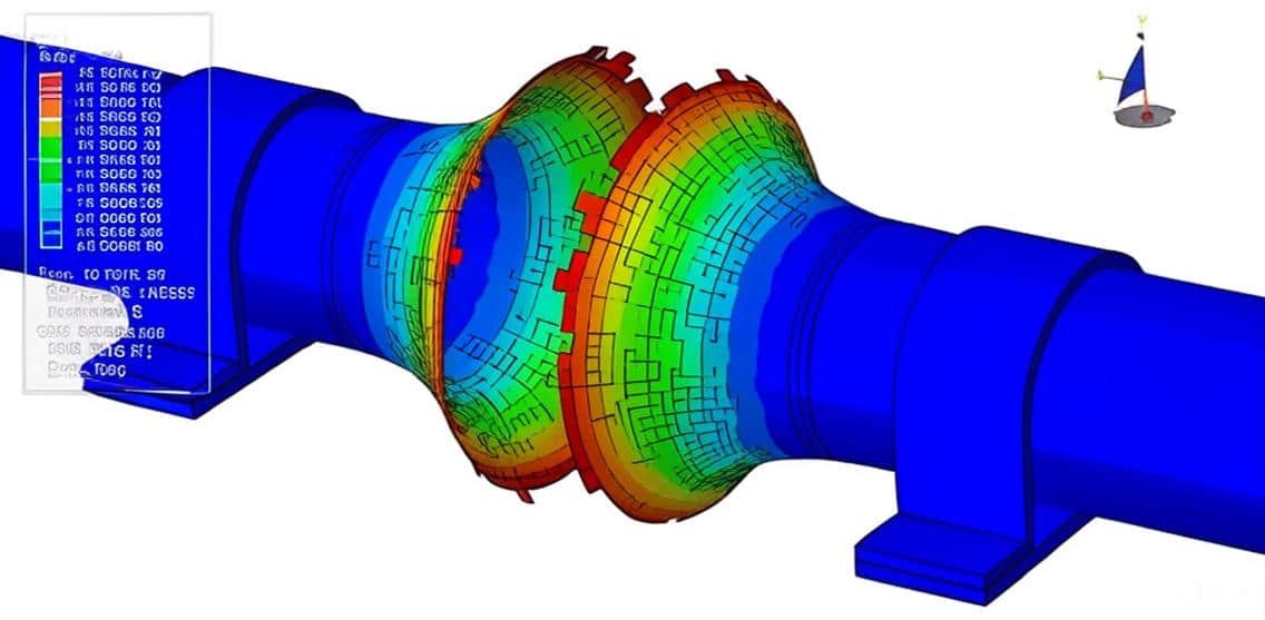
The simulation and analysis of pipes made from various materials—such as steel, aluminum, concrete, and composite materials—play a vital role in modern engineering design, infrastructure development, and industrial applications. By using advanced Finite Element Analysis (FEA) tools like Abaqus, engineers can accurately model, simulate, and predict the behavior of pipes under diverse loading and environmental conditions.

This package includes 21 tutorials that cover all about steel, concrete, aluminum, and concrete pipes. Analysis, including topics such as internal explosion using CONWEP, and the CEL method, corrosion, welding, bending, FRP reinforcement, creep, temperature modeling, explosive welding, impact, cyclic loading, and pipeline.

Pipes are fundamental components in transportation systems for fluids, gases, and slurries, as well as in structural applications such as bridges, tunnels, and offshore platforms. Each material type exhibits unique mechanical properties and performance characteristics:

  • Steel pipes offer high strength, ductility, and durability, making them ideal for high-pressure and structural applications.

  • Aluminum pipes are lightweight and corrosion-resistant, suitable for aerospace, marine, and lightweight industrial systems.

  • Concrete pipes provide rigidity and longevity in civil and infrastructure projects, such as water conveyance and sewage systems.

  • Composite pipes combine materials (e.g., fiber-reinforced polymers) to achieve a balance of strength, corrosion resistance, and reduced weight.

Using Abaqus’ Pipe simulation Package, engineers can simulate:

  • Static and dynamic loading conditions

  • Internal and external pressure effects

  • Thermal expansion and contraction

  • Fluid-structure interaction

  • Buckling, fatigue, and failure modes

Through such simulations, design optimization and performance verification can be achieved before physical prototyping, leading to cost savings, improved safety, and enhanced efficiency. The results enable informed decisions in selecting suitable materials, pipe dimensions, and joining methods for specific engineering applications.

Course Content

Example-1: Analysis of the composite pipe(aluminum-bamboo fiber-aluminum) under internal blast
In this lesson, the analysis of the composite pipe(aluminum-bamboo fiber-aluminum) under internal blast is studied. All three pipes are modeled as shell parts. The configuration of a composite pipe, which combines the advantages of joining two thin, stiff, and strong skins to a thick and low-density core, results in superior crushing characteristics and impact or blast resistance under out-of-plane loading when compared to single solid components. In this context, bamboo, a very abundant natural resource in tropical regions, has been exploited as a core material in composite pipes. To model aluminum under severe blast load, the Johnson-Cook hardening and damage model is selected. Abaqus/Explicit provides a dynamic failure model specifically for the Johnson-Cook plasticity model, which is suitable only for high-strain-rate deformation of metals. This model is referred to as the “Johnson-Cook dynamic failure model.” Abaqus/Explicit also offers a more general implementation of the Johnson-Cook failure model as part of the family of damage initiation criteria, which is the recommended technique for modeling progressive damage and failure of materials. The Hashin damage model is considered for the bamboo fiber pipe. Damage initiation refers to the onset of degradation at a material point. In Abaqus, the damage initiation criteria for fiber-reinforced composites are based on Hashin’s theory. These criteria consider four different damage initiation mechanisms: fiber tension, fiber compression, matrix tension, and matrix compression.

  • Abaqus Files
  • Document
  • Tutorial Video-1
    00:00
  • Tutorial Video-2
    00:00

Example-2: Four-point bending test modeling of an aluminum pipe reinforced with the CFRP
In this section, the four-point bending test modeling of an aluminum pipe reinforced with the CFRP is investigated. The aluminum pipe is modeled as a solid part; the CFRP pipes are modeled as four separate shell parts. Cohesive interaction property is considered among all layers. To model aluminum behavior, the elastic-plastic model with ductile, shear, and MSFLD damage criteria is selected. The CFRP layers are modeled as an elastic part with lamina damage behavior. The dynamic explicit, and general static steps can be used. The cohesive interlayer property is considered between the aluminum pipe and CFRP layers; cohesive interaction is considered among the CFRP layers.

Example-3: Analysis of the CFRP blanket effect on reducing the deformation of buried pipelines exposed to the subsurface explosion
In this case, the analysis of the CFRP blanket effect on reducing the deformation of buried pipelines exposed to the subsurface explosion is presented. The air, soil, and TNT are modeled as three-dimensional parts inside an Eulerian part. The steel pipe is modeled as a three-dimensional part. The CFRP blanket is modeled as three three-dimensional parts with some layers. Buried pipelines are vital arteries used to transport water, oil, and similar substances. Unfortunately, there have been different terrorist attacks against oil and gas pipelines in the last 28 years. This has highlighted the necessity of analyzing and designing pipelines that can 29 withstand such blast loads. The estimation of pipeline damage is a very complex work 30 because different factors, such as explosion, the transmission of energy to the soil and air, soil pipeline interaction, and pipeline behavior, affect the final results. Although analytical and empirical approaches have been widely used in explosion problems, numerical methods provide us with valuable information about the behavior of structural members with sophisticated behaviors. This study adopts the ideal gas equation of state to simulate air. The shaped charge is modeled using the Jones-Wikens-Lee (JWL) equation of state. This equation models the pressure induced by the release of the chemical energy of an explosion. This model is implemented using the so-called scheduled combustion structure in the sense that the explosion is not triggered via stressing explosive substances. Rather, the time traveling the explosion wave to each point is defined by the velocity of the explosion wave and the distance of each point from the explosion center. JWL equation of state can be written under the internal energy per unit mass of an explosive substance. Blast loads cause severe strains in pipes. Therefore, any model used for pipeline modeling should take strain rate into account. Johnson-Cook is a fit model for simulating the behavior of many materials, especially metals, under severe strain deformations. FRP is made of high-strength fibers inlaid in an epoxy resin substrate. GFRP is a conventional FRP composite produced as strips, sheets, tendons, or reinforcing columns. In addition to cost-effective execution advantage, FPRs show high strength, high formability, and remarkable energy absorption before the failure point.

Example-4: External pipe corrosion modeling of a steel pipe
In this lesson, the external pipe corrosion modeling of a steel pipe is studied. The steel pipe is modeled as a three-dimensional solid part. The defect is considered a radial arc on the external surface of the pipe. Pipeline corrosion is the oxidation and electrochemical breakdown of the structure of a pipe used to convey any substance. Pipeline corrosion occurs on both the inside and outside of any pipe and related structures, exposed to corrosive elements. The corrosion of steel piping and its associated components is a continuous and virtually unstoppable process. The end product, rust, is the result of an electrochemical reaction through which the higher energy processed metal is slowly reverted to its naturally occurring form. The steel material with an elastic-plastic model is selected. The general static step is so appropriate for this type of analysis. The internal pressure is applied to the internal surface of the pipe. The two ends of the pipe are fixed.

Example-5: Modeling of the internal explosion of a pipe with steel supports
In this section, the modeling of the internal explosion of a pipe with steel supports is investigated. The steel pipe is modeled as a three-dimensional solid part; it can also be a shell part. The upper and bottom supports are modeled as a three-dimensional solid part. To model the true behavior of the steel material, ductile, shear, and Johnson-Cook damage are used. The Johnson-Cook plasticity model: is a particular type of Mises plasticity model with analytical forms of the hardening, is suitable for high-strain-rate deformation of many materials, including most metals, is typically used in adiabatic transient dynamic simulations, can be used in conjunction with the Johnson-Cook dynamic failure model in Abaqus/Explicit, can be used in conjunction with the tensile failure model to model tensile spall or a pressure cutoff in Abaqus/Explicit, can be used in conjunction with the progressive damage and failure models. The ductile criterion is a phenomenological model for predicting the onset of damage resulting from the nucleation, growth, and coalescence of voids. The Johnson-Cook criterion (available only in Abaqus/Explicit) is a special case of the ductile criterion in which the equivalent plastic strain is used at the onset of damage. The shear criterion is a phenomenological model for predicting the onset of damage due to shear band localization. The dynamic explicit step is appropriate for this type of analysis. The perfect contact among the parts is considered. The CONWEP blast load procedure is selected to define the internal explosion in the pipe.

Example-6: Analysis of the CEL explosion in the depth of soil near a solid steel pipe
In this case, the analysis of the CEL explosion in the depth of soil near a solid steel pipe is presented. The Eulerian domain is modeled as a three-dimensional Eulerian part. The air, soil, and TNT are modeled as a three-dimensional solid part. The steel pipe is modeled as a three-dimensional solid part. Buried pressurized gas pipelines are bound to be threatened by accidental explosions in process industries, explosives factories, open pit mines, quarries, public works, or even intentional explosions near a pipeline. Terrorist attacks have unfortunately been increasing so that multiple explosions, in recent years, have taken place along the route of oil and gas transmission pipelines. Accordingly, blast loads and the design and analysis of buried structures under destructive dynamic loads have been of particular attention in recent years. To model steel pipe behavior under severe load, elastic-plastic material data is selected. The Johnson-Cook plasticity with Johnson-Cook damage to consider steel pipe failure during the detonation is used. To model air material, the ideal gas equation of state with dynamic viscosity is considered. To model soil behavior, elastic data with Mohr-Coulomb plasticity is used. The Jones-Wilkens-Lee (or JWL) equation of state models the pressure generated by the release of chemical energy in an explosive. This model is implemented in a form referred to as a programmed burn, which means that the reaction and initiation of the explosive is not determined by shock in the material. Instead, the initiation time is determined by a geometric construction using the detonation wave speed and the distance of the material point from the detonation points. The dynamic explicit step is appropriate for this type of analysis. The general contact capability with the contact property is used. The non-reflecting boundary is assigned to the outer surfaces of the Eulerian domain. The fixed boundary condition is assigned to the two ends of the pipe. The volume fraction method is used to define the location of each material in the Eulerian domain.

Example-7: Damage mechanics behavior of a pipeline under internal explosion
In this lesson, the damage mechanics behavior of a pipeline under internal explosion is studied. The steel pipe is modeled as a three-dimensional shell part. The soil is modeled as a three-dimensional solid part. Half of the steel pipe is placed inside the soil. The pipeline has characteristics such as a long conveying distance, high tube pressure, and a wide range of distribution. Once a tube bursts and other accidents occur, it is very easy to cause an explosion and combustion, resulting in immeasurable loss of life and property. Due to the variability of the medium conditions and the complexity of the boundary conditions, it is impossible to solve the problem of high-pressure pipeline blasting accurately. The Johnson-Cook plasticity model is selected for the steel pipe. It is a particular type of Mises plasticity model with analytical forms of the hardening law and rate dependence, suitable for high-strain-rate deformation of many materials, including most metals. The JC plasticity and damage model is used for the steel pipe to consider high-rate load and damage during the blast load. The Mohr-Coulomb plasticity model is selected for the soil material. The dynamic explicit step is appropriate for this type of analysis. The general contact capability with friction as contact behavior is used. To define the contact between the lower surface of the steel pipe and soil, the ideal contact or tie constraint is selected. The CONWEP blast procedure by using the TNT definition as the incident wave, is used. The fixed boundary condition is assigned to the bottom surface of the soil, and the pin boundary condition to the two ends of the pipe.

Example-8: Rigid ball impact modeling on the steel pipe with and without the CFRP reinforcement layers
In this section, the rigid ball impact modeling on the steel pipe with and without the CFRP reinforcement layers is investigated. The steel pipe is modeled as a three-dimensional shell part. The CFRP pipe is modeled as a three-dimensional shell part, and a conventional shell section with eight layers is considered for it. In the first analysis, the rigid ball impact on the steel pipe without CFRP reinforcement is performed. The elastic-plastic material model with ductile damage criterion is considered to predict the damage during the impact. The dynamic explicit step with surface-to-surface contact is selected. The fixed boundary condition is assigned to the two ends of the steel pipe, and the initial velocity is assigned to the rigid ball. After the first analysis, the plastic strain, damage, and displacement are available. In the second simulation, the CFRP is added to the middle of the steel part. The elastic material as a lamina formulation and Hashin’s damage criterion are used to model the proper behavior of the CFRP pipe. The conventional shell section with eight different layers is considered for the composite part. The surface-to-surface contact with the contact property is selected between the composite and the rigid ball. The ideal contact between the CFRP pipe and the steel pipe is assigned. After the simulation, all results are obtainable. The CFRP layers have a good effect on the reduction of plastic strain, displacement of the steel pipe, and also reduce the steel pipe damage.

Example-9: Static bending analysis of the UHPC beam with CFRP pipe core
In this case, the static bending analysis of the UHPC beam with CFRP pipe core is done through a comprehensive tutorial. The concrete beam is modeled as a three-dimensional solid part. The CFRP pipe core is modeled as a three-dimensional shell part. The rigid body part is used as a force body. It is widely accepted that composite structures can contribute to a more effective and efficient structural system. In recent years, fiber-reinforced polymer (FRP) composite structures have found wide application in civil engineering. The characteristics of FRP include a high strength-to-weight ratio, high durability (especially corrosion resistance), and good installation properties. Although concrete is the most universally used material in building, there are still some limitations to its use, such as low tensile strength and brittleness. Ultra-High Performance Concrete (UHPC), a cutting-edge concrete, may be able to overcome these concerns. To model Ultra-High-Performance concrete material, the Concrete Damage Plasticity model is used to consider both tensile and compressive behavior. To model CFRP composite material, the lamina elasticity and Hashin’s damage criterion are used to predict the damage during bending. The general static step with some changes in the convergence model to avoid early non-convergence is used. The perfect contact, instead of surface-to-surface contact, is assumed between the CFRP pipe and the concrete inner surface. The general contact algorithm with friction property is considered for all other contacts in the contact domain.

Example-10: Analysis of the internal explosion inside the aluminum pipe reinforced with epoxy glue and steel cover
In this lesson, the analysis of the internal explosion inside the aluminum pipe reinforced with epoxy glue and a steel cover is studied. The aluminum, epoxy, and steel covers are modeled as three-dimensional solid parts. The aluminum material is used for the internal pipe with elastic and Johnson-Cook plasticity behavior. To predict the damage and failure during the blast load, Johson-Cook damage is considered for the aluminum pipe. The epoxy material is used to model adhesive material between two metal pip,es and for that, traction elasticity with damage data for the traction-separation law is implied. The steel material with elastic-plastic behavior coupled with ductile and shear damage, is selected for the external metal cover. The dynamic explicit procedure is appropriate for this type of analysis. The perfect or ideal contact is assumed between adhesive and steel, adhesive and aluminum pipe. The CONWEP blast load procedure is used to model the blast load over the internal surface of the aluminum part. The source point for the TNT is assumed at the center of the aluminum pipe with one kg, all results, such as stress, strain, damage, …are obtainable. The aluminum pipe and adhesive material are completely damaged, but the steel cover has remained without damage.

Example-11: Dynamic bending behavior modeling of the concrete pipe strengthening with epoxy
In this section, the dynamic bending behavior modeling of the concrete pipe strengthening with epoxy is investigated. Pipelines are an essential component of a city’s infrastructure. Compared to other structures, buried infrastructures have a higher risk of deterioration due to the particularly harsh surrounding environment. Deterioration is a loss of structural capacity with time as the result of external factors such as overloading, earthquakes, and cyclones, or material weakening in an aggressive environment such as sulfuric acid-induced corrosion and chloride-ion penetration. Pipeline failures can cause the potential of flooding neighborhoods and residences, traffic disruption, and pollution of underground water resources, and can result in costly consequences. Spray-on lining with concrete/cement mortar is the oldest method of pipeline rehabilitation. In this method, a polymeric lining like epoxy and polyurethane or cement mortar is sprayed inside the deteriorated pipe to stop internal corrosion, potentially restore hydraulic capacity, and eliminate water quality deterioration arising from, for instance, iron or steel corrosion and associated scaling. The ability to achieve one-day return to service, nearly effortless service reconnections, minimal community impacts, and low installation costs are the main attractive features of spray-on lining compared to other rehabilitation methods used for water mains. Uncertainty about the structural benefits of these linings has always categorized their applications as a “non-structural” rehabilitation method. The Concrete Damaged Plasticity model is used to define concrete pipe behavior under dynamic bending load. The model is a continuum, plasticity-based, damage model for concrete. It assumes that the two main failure mechanisms are tensile cracking and compressive crushing of the concrete material. The epoxy is modeled as an elastic material type with a traction separation law to define damage and failure behavior during the dynamic bending load. The dynamic explicit step is appropriate for this type of analysis. The surface-to-surface contact algorithm with contact property is used between rigid bodies and the concrete pipe. The perfect contact is assumed between the internal surface of the concrete pipe and the outer surface of the epoxy part. The fixed boundary condition is assigned to the two bottom rigid bodies and a displacement boundary to the two top rigid bodies, with a smooth amplitude to apply a smooth load.

Example-12: Analysis of the CEL explosion inside the steel pipe embedded in the depth of soil
In this case, the analysis of the CEL explosion inside the steel pipe embedded in the depth of soil is presented. The pipe is modeled as a three-dimensional shell part. The TNT, soil, and air are modeled as a three-dimensional solid part. The Eulerian part is modeled as a three-dimensional Eulerian part. The steel material is used for the pipe as an elastic-plastic material with ductile and shear damage criteria to predict the failed zone after the detonation. The TNT behavior is modeled as an equation of state, and that is JWL, which can convert chemical energy released from the explosion process to mechanical pressure. The air is modeled as an ideal gas with viscosity. To model soil behavior, Mohr-Coulomb plasticity is used. The dynamic explicit step is appropriate for this type of analysis. The general contact interaction with the contact property. The fixed boundary condition is assigned to the ends of the pipe, and Eulerian boundaries are assigned to the Eulerian domain. The volume fraction method is used to calculate the volume of the TNT, soil, and air.

Example-13: Three-point bending test of a steel pipe reinforced with CFRP
In this lesson, the three-point bending test of a steel pipe reinforced with CFRP is studied. Circular hollow sections (CHS) are widely used in many applications, but predominantly used as pipelines in the oil and gas industry. Natural resources like oil and gas constitute a major share of global fossil fuel, which is the dominant source of energy in the world. The advancement of human civilization and scarcity of natural resources like oil, natural gases, and minerals have led to exploring deeper into the earth’s crust and to expand the venture in remote locations; eventually increasing underground, high-pressure ashore, and subsea drilling activities. Metal pipelines are the most efficient and safest way to transport these natural resources over long distances. At present, most of the pipeline systems consist predominantly of steel pipes due to their high strength, relative to the simplicity of joints, and low cost The steel pipe and CFRP pipe are modeled as three-dimensional shell parts. Elastic plastic material for steel pipe and elastic behavior as an engineering constant, with Hashin’s damage criterion for CFRP, are used. Because of the large deformation, a dynamic explicit step with mass scale to hasten the simulation is used. Surface-to-surface contact between rigid bodies and steel pipe-composite, with a general contact to consider the other interactions, is used. The contact between the steep pipe and the CRFP pipe is considered a perfect contact.

Example-14: Creep phenomenon analysis of a steel pipe
In this section, the creep phenomenon analysis of a steel pipe is investigated. Creep is a time-dependent deformation of a material while under an applied load that is below its yield strength. It most often occurs at elevated temperatures, but some materials creep at room temperature. Creep terminates in rupture if steps are not taken to bring it to a halt. Creep data for general design use are usually obtained under conditions of constant uniaxial loading and constant temperature. Results of tests are usually plotted as strain versus time up to rupture. As indicated in the image, creep often takes place in three stages. In the initial stage, strain occurs at a relatively rapid rate, but the rate gradually decreases until it becomes approximately constant during the second stage. This constant creep rate is called the minimum creep rate or steady-state creep rate since it is the slowest creep rate during the test. In the third stage, the strain rate increases until failure occurs. Creep in service is usually affected by changing conditions of loading and temperature, and the number of possible stress-temperature-time combinations is infinite. While most materials are subject to creep, the creep mechanisms are often different between metals, plastics, rubber, and concrete In this tutorial, the steel pipe with a branch is modeled as a three-dimensional part. The elastic and creep plasticity have been implied for the material. For this analysis, two steps as static and viscoelastic, have been used. The symmetry boundary and internal pressure as a load have been applied to the pipe.

Example-15: Thermal-stress analysis of the arc welding between two pipes using the DFLUX subroutine
In this case, the thermal-stress analysis of the arc welding between two pipes using the DFLUX subroutine is presented. Arc welding is one of the most widely used joining processes in the fabrication and repair of steel pipelines used in industries such as oil and gas, petrochemical, and power generation. It involves the use of an electric arc to generate intense heat that melts the base metals and filler material, creating a metallurgical bond upon cooling. However, the localized and rapid heating and cooling cycles inherent to the process lead to significant thermal gradients and non-uniform plastic deformations within the welded joint region.These thermal cycles generate residual stresses and distortion in the welded structure, which can adversely affect the mechanical integrity, fatigue life, and dimensional accuracy of the pipeline. Understanding and predicting these effects are therefore critical to ensuring safe and reliable performance during service.To address this, thermal-stress analysis using Finite Element Analysis (FEA) tools such as Abaqus provides a robust numerical approach to simulate the transient heat transfer and subsequent stress development during and after the welding process. Arc welding is one of several fusion processes for joining metals. By applying intense heat, metal at the joint between two parts is melted and caused to intermix – directly, or more commonly, with an intermediate molten filler metal. Upon cooling and solidification, a metallurgical bond is created. Since the joining is an intermixture of metals, the final weldment potentially has the same strength properties as the metal of the parts. This is in sharp contrast to non-fusion processes of joining (i.e., soldering, brazing, etc.) in which the mechanical and physical properties of the base materials cannot be duplicated at the joint. In this tutorial, steel material for pipes and the DFLUX subroutine to create non-uniform heat distribution have been used.

Example-16: Arc welding temperature modeling of a steel pipe using the DFLUX subroutine
In this lesson, the arc welding temperature modeling of a steel pipe using the DFLUX subroutine is studied. Arc welding is one of the most widely used joining processes in the fabrication and repair of steel pipelines used in industries such as oil and gas, petrochemical, and power generation. It involves the use of an electric arc to generate intense heat that melts the base metals and filler material, creating a metallurgical bond upon cooling. However, the localized and rapid heating and cooling cycles inherent to the process lead to significant thermal gradients and non-uniform plastic deformations within the welded joint region.These thermal cycles generate residual stresses and distortion in the welded structure, which can adversely affect the mechanical integrity, fatigue life, and dimensional accuracy of the pipeline. Understanding and predicting these effects are therefore critical to ensuring safe and reliable performance during service.To address this, thermal-stress analysis using Finite Element Analysis (FEA) tools such as Abaqus provides a robust numerical approach to simulate the transient heat transfer and subsequent stress development during and after the welding process. Fusion welding is a joining process in which the coalescence of metals is achieved by fusion. This form of welding is widely employed in fabricating structures such as ships, offshore structures, steel bridges, and pressure vessels. In this study, the heat from the moving welding arc was applied as a volumetric heat source with a double ellipsoidal distribution proposed by the Goldak model. The moving heat source was modeled by ABAQUS user subroutine DFLUX in the ABAQUS code. As for the boundary conditions applied to the thermal model, convection and radiation were both used as interactions.

Example-17: Impact analysis against water-filled X65 steel pipes
In this section, the impact analysis against water-filled X65 steel pipes is investigated. Offshore pipelines are frequently subjected to accidental impact loads, e.g., from anchors or trawl gear. A lot of parameters, including the pipe geometry, material properties, pipeline content, impact velocity, etc. This video presents Impact Simulation against water-filled X65 steel pipes in ABAQUS by using SPH(Smooth Particle Hydrodynamics). An explicit procedure is appropriate for this type of analysis.

Example-18: Modeling of the Eulerian explosion on a steel pipeline in the depth of soil
In this case, the modeling of the Eulerian explosion on a steel pipeline in the depth of soil is done through a practical tutorial. The safety and reliability of buried steel pipelines are of paramount importance in industries such as oil and gas transportation, petrochemicals, and water distribution. However, these pipelines are often exposed to extreme loading conditions, including underground explosions, which can result from accidental detonations, mining activities, or deliberate attacks. Understanding the dynamic response of buried pipelines under such high-intensity blast loads is crucial for assessing their structural integrity and designing protective measures.Modeling these phenomena poses significant challenges due to the highly nonlinear, transient, and coupled nature of the explosion event. The blast wave propagates through the surrounding soil and interacts with the pipeline, producing shock waves, large deformations, and material failure. To accurately capture these complex interactions, the Eulerian–Lagrangian coupling approach within Abaqus/Explicit provides a robust and physically accurate simulation framework. Existing studies on the response of buried steel pipelines to explosions generally concern finding a safe distance from the explosion where the pipeline does not undergo plastic deformation, while intentional explosions impose intense deformations on steel pipelines. In the present video Eulerian explosion over a pipeline has been simulated. JWL equation of state for TNT, Us-Up for air, Johnson-Cook material model for steel, and Mohr-Coulomb plasticity for soil have been used.

Example-19: Cyclic loading analysis of a steel pipe
In this lesson, the cyclic loading analysis of a steel pipe is studied. Steel pipes are essential components in various engineering systems, including oil and gas transportation, offshore structures, power plants, and mechanical frameworks. These structures are often subjected to cyclic or repeated loading conditions, such as internal pressure fluctuations, vibration from machinery, wind or wave actions, and temperature variations. Over time, such cyclic stresses can lead to progressive material degradation, crack initiation, and fatigue failure, even if the applied stresses are below the material’s yield strength. To ensure long-term reliability and safety, it is critical to understand and predict the cyclic response and fatigue life of steel pipes. The cyclic loading analysis provides valuable insight into how the pipe’s mechanical properties, geometry, and loading patterns influence its stress–strain behavior over repeated cycles. Using Finite Element Analysis (FEA) tools such as Abaqus, engineers can simulate the cyclic loading process and evaluate both elastic–plastic deformation and accumulated damage under different load conditions. For this type of analysis, we need to define a specific plasticity, such as Combined plasticity with cyclic hardening.

Example-20: Explosive welding simulation between the titanium and steel pipe
In this section, the explosive welding simulation between the titanium and steel pipe is investigated. Explosive welding (EXW) is a solid-state joining process that uses controlled explosive energy to create a high-velocity impact between two dissimilar metals, resulting in a strong metallurgical bond without significant melting at the interface. This technique is particularly advantageous for joining materials with vastly different mechanical, thermal, and chemical properties, such as titanium and steel, which are otherwise difficult or impossible to weld using conventional fusion-based methods.In industries such as aerospace, chemical processing, power generation, and marine engineering, the combination of titanium’s excellent corrosion resistance and steel’s high strength and cost-effectiveness makes this joint highly desirable. Explosive welding enables the formation of bimetallic transition joints or clad pipes, which can withstand harsh environments while maintaining structural integrity and economic viability.During the process, a controlled detonation propels the titanium plate or pipe (flyer) toward the steel substrate (base) at extremely high velocities—typically between 2000 and 3000 m/s. Upon impact, the high strain rate and localized plastic deformation cause the oxide films to break, leading to metallic jet formation that cleans and activates the surfaces. A wavy interfacial structure is often produced, characteristic of a high-quality explosive weld, which enhances the mechanical interlocking and bond strength between the dissimilar metals. The internal pipe or flyer pipe is made of Titanium, and the external pipe or base pipe is made of steel. Two pipes have been modeled as axisymmetric parts and TNT-like them. For modeling TNT behavior JWL equation of state has been used. During the process Ti pipe moves like a flyer pipe toward the Steel pipe. TNT created huge pressure on the flyer pipe and caused a joint as a weld between the interference surfaces of two pipes

Example-21: Analysis of the Eulerian explosion inside a pipe
In this case, the analysis of the Eulerian explosion inside a pipe is presented. Explosions occurring inside steel pipes represent a critical engineering and safety concern in industries such as oil and gas transport, chemical processing, defense, and power systems. Internal explosions—caused by combustion of gases, detonation of explosives, or accidental overpressure events—can subject the pipe walls to extreme transient loads, high strain rates, and complex fluid–structure interactions. Understanding the resulting pressure wave propagation, structural response, and failure mechanisms is essential for ensuring the integrity and resilience of pressurized pipeline systems.The analysis of an internal explosion involves capturing both the thermodynamic behavior of the detonation gases and the dynamic response of the pipe structure. Because explosions involve rapidly expanding gases and large deformations, a fully coupled Eulerian–Lagrangian approach is often employed in Abaqus/Explicit or similar simulation environments. TNT and Air have been modeled as Eulerian parts, and the pipe as a Lagrangian part. For modeling TNT behavior JWL equation of state and for the air, Us-Up has been used.

Reviews

No Review Yet
No Review Yet
227,00 498,00
26 people watching this product now!

Material Includes

  • 1- Abaqus Files+ Codes
  • 2- Documents
  • 3- Tutorial Videos

Audience

  • 1- Mechanical Engineering
  • 2- Civil Engineering
  • 3- Structural Engineering
  • and other fields

Related  Products

See more

Want to receive push notifications for all major on-site activities?