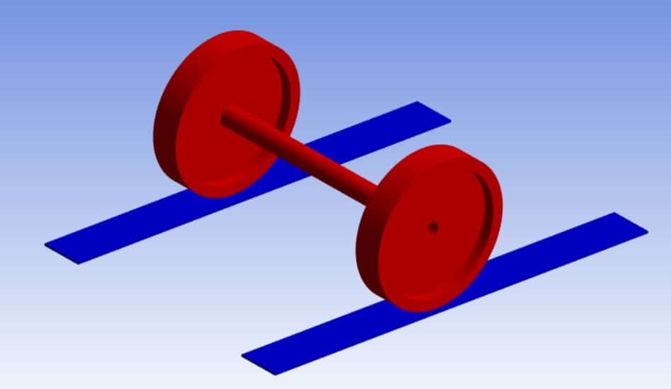
The mechanical interaction between tyres and the underlying surface plays a crucial role in vehicle performance, safety, and durability. When a tyre rolls on a surface, complex contact phenomena occur due to the combined effects of normal loading, tangential friction, material deformation, and dynamic motion. This interaction is inherently non-linear, arising from large deformations, material non-linearities (such as hyperelastic rubber behavior), and non-linear contact mechanics.
Finite Element Analysis (FEA) provides a robust numerical approach to investigate these behaviors in detail. Using ANSYS Workbench, the rolling tyre–rubber surface problem can be modeled with realistic geometry, material models, and boundary conditions to simulate the actual contact behavior. This includes capturing the contact stress distribution, frictional stress patterns, and the overall deformation response during rolling.
Such simulations are valuable for applications in automotive engineering, rail wheel design, and material testing, where understanding stress distribution helps optimize designs, enhance safety, and reduce wear.
In the finite element model, both the wheels and the contact surface are assigned a hyperelastic rubber material model to accurately capture large deformations, non-linear stress–strain response, and nearly incompressible behavior typical of elastomers. The axle is modeled as stainless steel, defined with linear elastic isotropic properties, since its deformation is expected to be minimal compared to the rubber components. This combination of materials introduces material nonlinearity into the analysis, which is handled by ANSYS’s nonlinear solver capabilities.
The interaction between the wheels and the axle is modeled as bonded contact in ANSYS, ensuring no relative motion or separation occurs at this interface, simulating a rigid connection in real-life assembly. The contact between the wheels and the rubber surface is defined as frictional surface-to-surface contact with finite sliding enabled, allowing large relative motion during rolling. A Coulomb friction model is applied to replicate tangential traction, stick–slip behavior, and energy dissipation due to friction. To accurately simulate the rolling phenomenon, planar joints are defined in the Mechanical environment for both wheels. These joints constrain unnecessary degrees of freedom while allowing rotation about the wheel axis, enabling realistic rolling motion under the applied loads.
A bearing load is applied on the mid-surface of the axle to represent the vertical load transmitted from the vehicle body or supporting structure. This load is distributed evenly along the bearing surface to avoid local stress concentrations. To simulate rolling over a specified distance, a prescribed displacement (travel distance) is applied to the axle assembly in the horizontal direction. The rubber surface (ground) is fixed in all degrees of freedom at its base, preventing any translation or rotation, thereby replicating a rigid support condition in the model. These boundary conditions ensure that all motion is generated by the wheel–ground interaction, allowing the solver to predict realistic contact pressure distribution, frictional shear stress, and deformation patterns during the rolling motion.

Abaqus
€81,00 €39,00

Abaqus
€299,00 €249,00

Uncategorized
€95,00 €80,00
Abaqus
€79,00 €38,00
Abaqus
€68,00 €34,00
Abaqus
€77,00 €39,00
Abaqus
€79,00 €39,00
See more

Want to receive push notifications for all major on-site activities?