Engineering Downloads

Let’s Learn and Collaborate

Engineering Downloads

Forming Analysis Package in Abaqus

195,00 415,00
195,00 415,00
30 people watching this product now!

Material Includes

  • 1- Abaqus Files
  • 2- Document
  • 3- Tutorial Videos

Audience

  • 1- Mechanical Engineering
  • 2- Manufacturing Engineering
  • 3- Aerospace Engineering

What You Will Learn?

  • This package includes 15 tutorials covering all the forming analysis in Abaqus, which consider various materials, including aluminum, steel, composite, and foam. You'll become a master in modeling and simulating the forming process during this comprehensive course.

About Course

Introduction to Metal Forming Analysis

Metal forming is a key manufacturing process where metal is plastically deformed into a desired shape without material removal. Instead of cutting, material is reshaped by applying external forces through tools such as dies, punches, and rollers. Common metal forming processes include forging, extrusion, rolling, drawing, bending, drilling, composite forming, waterjet cutting, and stamping.

To design these processes efficiently and predict outcomes, engineers use metal forming analysis. This analysis applies engineering principles and computational simulations to understand how metals behave during deformation.

This package includes 15 tutorials that cover all that you need to know about the forming process in Abaqus. 

Objectives of Metal Forming Analysis

  1. Predict material flow – Understanding how the metal will deform under loads.
  2. Determine stress and strain distribution – Identifying regions of high strain and possible failure.
  3. Evaluate forming load and energy requirements – Calculating press capacity or rolling forces.
  4. Identify potential defects – Such as wrinkling, tearing, springback, or uneven thickness.
  5. Optimize tool and die design – Ensuring long life and minimal manufacturing cost.

Key Factors Considered in Metal Forming Analysis

  • Material properties: Stress-strain curve, strain hardening, and anisotropy.
  • Process parameters: Temperature, speed of forming, and lubrication.
  • Tool geometry: Shape and alignment of dies, punches, or rolls.
  • Friction conditions: Interaction between tool and workpiece.

Simulation in Metal Forming

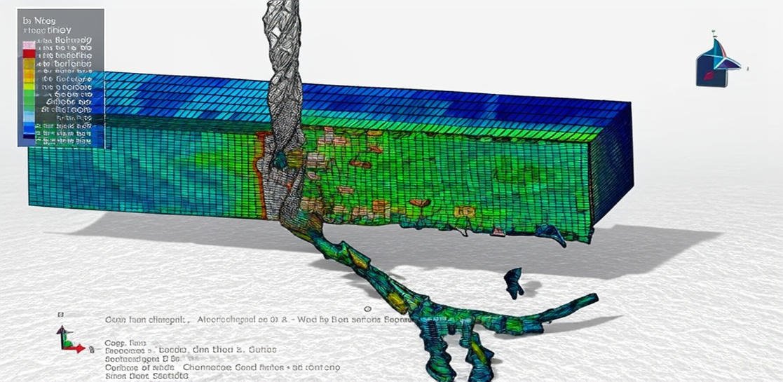
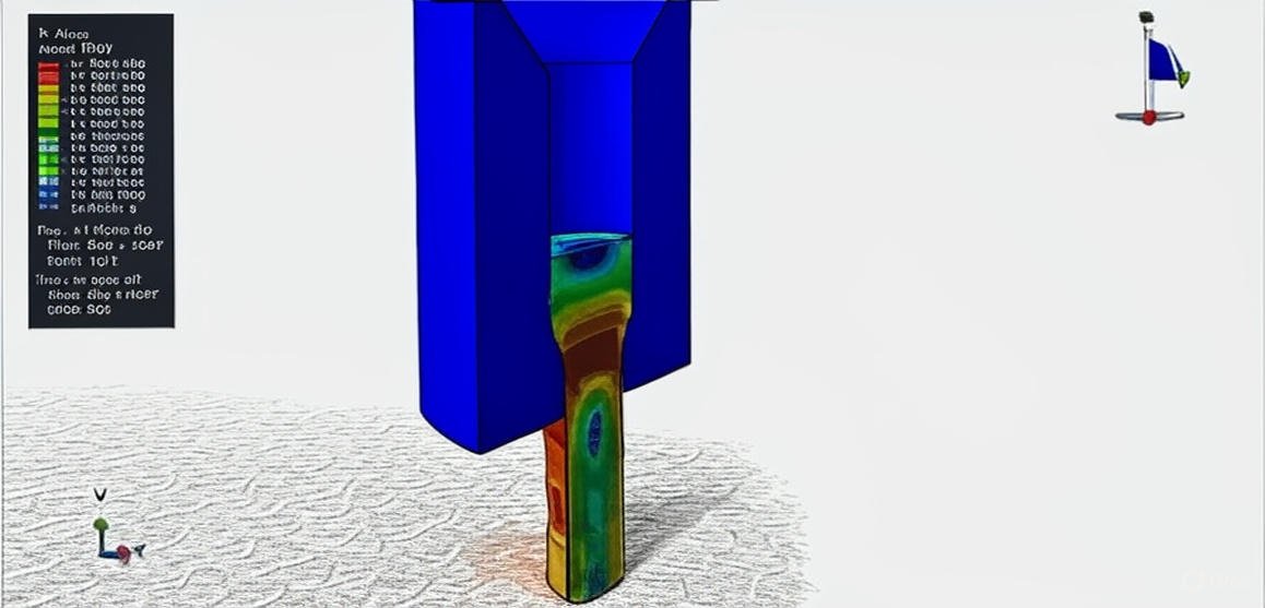
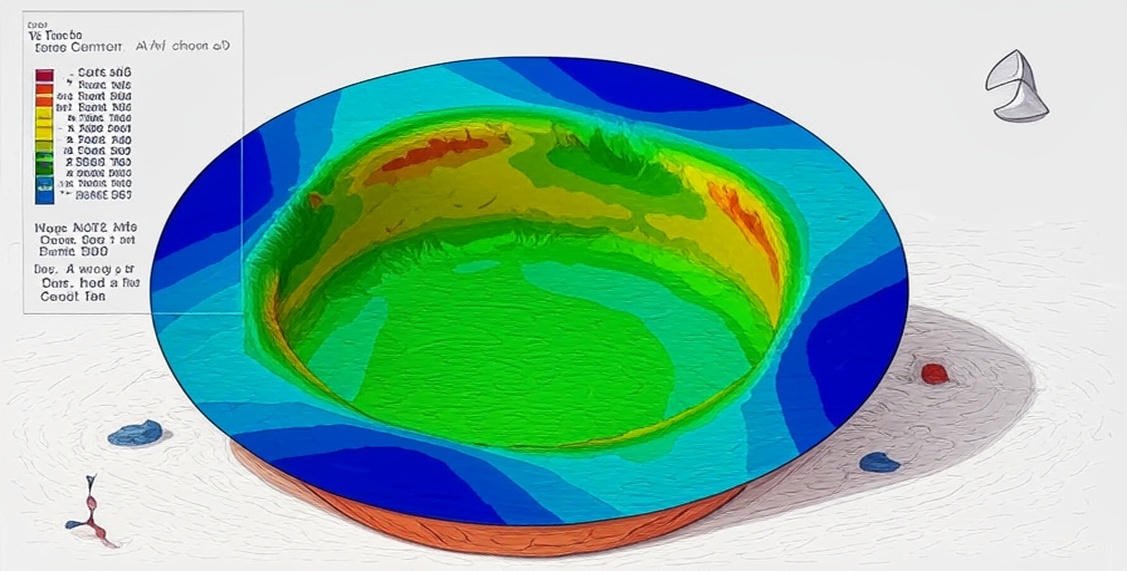
With modern Finite Element Analysis (FEA) tools like Abaqus, engineers can create detailed simulations of forming processes. These simulations help to:

  • Visualize deformation and metal flow.
  • Predict failure zones and thinning.
  • Reduce the need for expensive trial-and-error experiments.
  • Optimize process parameters for efficiency and product quality.

Course Content

Example-1: Forming process of the steel-CFRP-steel composite plate
In this lesson, the forming process of the steel-CFRP-steel composite plate is studied using Abaqus. The two steel plates are modeled as a three-dimensional shell part. The CFRP core is modeled as a three-dimensional shell part with four layers. The die and punch are modeled as analytical rigid parts. The elastic-plastic material model is selected for the steel parts, and the lamina elasticity with Hashin’s damage criterion is chosen to model the CFRP material. The dynamic explicit step with the mass scale technique is used to consider the dynamic process of forming. The surface-to-surface contact with the property is selected for the punch, die, and steel plates. In the context of scarcer fossil raw materials and rising fuel prices, lightweight designs are increasingly entering the automotive industry. One of the key objectives in the development of future car generations is the reduction of fuel consumption and, concomitantly, the reduction of pollutant and CO2 emissions. A reduction in the vehicle weight leads to a greater ratio of payload to deadweight and, in addition, functions such as acceleration and driving dynamics are better met. A lower mass results in lower acceleration, ascent, and rolling resistances. A common approach is the substitution of high-density materials, such as steel, with lighter, low-density materials with high strength, such as CFRP. Significant weight advantages can be realized by using composite materials. However, the high material costs and the necessity of employing manual manufacturing processes limit the use of just composites to the high-priced car segment. One promising approach is structural components in a multi-material design, such as hybrid parts made of high-strength steel with local CFRP reinforcements. Such hybrid components have cost advantages compared with exclusively CFRP components and can be reinforced in a load-adapted manner.

  • Abaqus Files
  • Document
  • Tutorial Video
    26:22

Example-2: Electro-Hydraulic forming process-Validation model
In this section, the Electro-Hydraulic forming process in Abaqus is investigated through a practical tutorial. This example is a validation model of a related paper. Electro-hydraulic forming is one of the methods that is highly considered among automotive specialists. This method is known as the “high strain rate forming” method. In this process, an electrical discharge within a liquid medium transforms the electrical energy into mechanical energy. Severe discharge of electrical energy creates a plasma channel that leads to evaporation of the water between two electrodes and generates a high-speed shock wave propagating towards the workpiece. Thus, the sheet moves into the die cavity and reaches its desired shape. Carrying the force by the liquid medium, the need for a punch is revoked. Compared with electromagnetic forming, this process can form versatile metals due to its non-sensitivity to conduction. A dynamic explicit procedure is appropriate for this type of analysis. Surface-to-surface contact between die and blank, and tie constraint between blank and water are used. The acoustic interaction is assigned to the water part.

Example-3: Electro-Hydraulic Forming of Sheet by using a time pressure curve
In this case, the Electro-Hydraulic Forming of Sheet by using a time pressure curve in Abaqus is done through a comprehensive tutorial. In this simulation Finite Element simulation of Electro-Hydraulic Forming of Sheet by using a time pressure curve in Abaqus has been investigated. Sheet metal forming processes are those in which force is applied to a piece of sheet metal to modify its geometry rather than remove any material. The applied force stresses the metal beyond its yield strength, causing the material to plastically deform, but not to fail. By doing so, the sheet can be bent or stretched into a variety of complex shapes. The conventional sheet metal forming processes include bending, roll forming, deep drawing, and stretch forming. With advancements in technology, several high-strain-rate forming processes like explosive metal forming process, electro-magnetic pulse forming, and electro-hydraulic forming processes, which are based on high-pressure pulse generation using different sources of energy, are being used frequently in the industry. In this simulation, the validation of the paper has been done, and the simulation has good appropriateness with the paper. A dynamic explicit step with surface-to-surface contact has been used. The time-pressure curve is used to model the pressure pulse.

Example-4: Explosive forming by using the CEL method
In this lesson, the explosive forming by using the CEL method in Abaqus software is studied. A food processing equipment using the underwater shock wave has been developed in Japan. The processing mechanism is crushed with the spalling phenomenon of the shock wave. The effect is extraction improving, softening, sterilizing, etc., with non-heating. The pressure vessel for crushing for the processing of a variety of foods has been designed and manufactured. We need a pressure vessel for food processing by underwater shock waves. Therefore, we propose making the pressure vessel by explosive forming. Only a few of these pressure vessels will be made. One design suggestion for the pressure vessel made of stainless steel was considered. The steel plate is modeled as three three-dimensional shells with Johnson-Cook plasticity, TNT as an Eulerian part with the JWL material model, and water with the Us-Up equations. A dynamic explicit procedure is appropriate for this type of analysis. The interaction between the die and plate, holder and plate is considered as surface-to-surface contact. The volume fraction method is used to define the Eulerian material link between the TNT and water.

Example-5: Single point incremental forming (SPIF)
In this section, the single point incremental forming (SPIF) in Abaqus software is investigated. Single-point incremental forming is a flexible process that uses very simple tooling to make sheet metal prototypes and custom-specific parts. In this, the sheet is clamped along its edges, and a hemispherical-headed tool is moved along the required path so that it presses the sheet locally along the path. Better formability, simple tooling without any dedicated dies, and low forming forces are some of the attractive features of this process. However, it suffers from some disadvantages, such as long processing time, poor dimensional accuracy due to the bending of the sheet near the clamped edges. Tool diameter, step depth, feed rate, rotational speed of the spindle, sheet thickness, lubrication, and tool path are some of the important process parameters that affect the process. Mechanics in incremental forming. Tool path plays a vital role in the geometric accuracy of the part and homogeneous thickness distribution. Thus, the proper tool path selection is very important for the successful production of parts in incremental forming. Other ways of improving the accuracy of the part are by using the contour tool, partial or full die below the sheet.A dynamic explicit procedure is appropriate for this type of analysis, and surface-to-surface contact is selected for the contact algorithm.

Example-6: Hydroforming process modeling
In this case, the hydroforming process modeling is done in Abaqus by using the SPH formulation for the fluid. Hydroforming is a metal fabricating and forming process that allows the shaping of metals such as steel, stainless steel, copper, aluminum, and brass. This process is a cost-effective and specialized type of die molding that utilizes highly pressurized fluid to form metal. Generally, there are two classifications used to describe hydroforming: sheet hydroforming and tube hydroforming. Sheet hydroforming uses one die and a sheet of metal; the blank sheet is driven into the die by high-pressure water on one side of the sheet, forming the desired shape. Tube hydroforming is the expansion of metal tubes into a shape using two die halves, which contain the raw tube. Hydroforming is used to replace the older process of stamping two-part halves and welding them together. It is also used to make parts both more efficiently by eliminating welding, as well as creating complex shapes and contours. Parts created in this method have a number of manufacturing benefits, including seamless bonding, increased part strength, and the ability to maintain high-quality surfaces for finishing purposes. When compared to traditional metal stamped and welded parts, hydroformed parts are lightweight, have a lower cost per unit, and are made with a higher stiffness-to-weight ratio. The processes can also be utilized in the single-stage production of components, saving labor, tools, and materials. Aluminium material is used for the sheet, and water is modeled as the Us-Up equation of state. A dynamic explicit step with surface-to-surface contact has been used. In this simulation, Smooth Particle Hydrodynamic(SPH) is used to model water behavior. During the simulation, the punch moved into the water, and water moved to the sheet and causing huge pressure over it, and after a moment the forming of the sheet is obvious.

Example-7: Temperature analysis of the chip forming process
In this lesson, the temperature analysis of the chip forming process in Abaqus is done through a comprehensive tutorial. All parts are modeled as three-dimensional with thermal properties as conductivity, specific heat, and expansion… to consider their variation. A dynamic temp-explicit procedure is appropriate for this type of analysis. During the process temperature has changed, and the heat is divided between the cutter and the piece.

Example-8: Three-dimensional cold extrusion process of an aluminum rod
In this section, the three-dimensional cold extrusion process of an aluminum rod is done. The aluminum rod and die are modeled as a three-dimensional solid part. The aluminum material is considered an elastic material with plastic data that depends on temperature. The conductivity, specific heat, expansion coefficient, and inelastic heat fraction are used because of the thermally coupled step which is used. A fully coupled temperature-displacement analysis is performed with the die kept at a constant temperature. In addition, an adiabatic analysis is presented using Abaqus/Standard without accounting for frictional heat generation. Both the node-to-surface (default) and the surface-to-surface contact formulations in Abaqus/Standard are presented. Four steps are used in this tutorial. In the first step, the contact establishment is considered. In the second step, the extrusion process is done. In the third step, the contacts are removed. In the fourth step, the cooling process is applied. The convection as a surface file condition is selected for the metal barputer surfaces. The surface-to-surface contact with friction and heat generation as a property is selected.

Example-9: Drilling process of the aluminum alloy
In this case, the drilling process of the aluminum alloy is investigated through a practical tutorial. The tool is modeled as a rigid shell part, and the aluminum part is modeled as a three-dimensional solid part. To model aluminum behavior, the elastic-plastic material with ductile and shear damage model is used. The ductile model assumes that the equivalent plastic strain at the onset of damage is a function of stress triaxiality and strain rate. The shear damage initiation criterion is a model for predicting the onset of damage due to shear band localization. The model assumes that the equivalent plastic strain at the onset of damage is a function of the shear stress ratio and strain rate. During the simulation, the tool can penetrate and remove the elements. The dynamic explicit procedure is appropriate for this type of analysis. The mass scale technique is used to reduce the time of the simulation and ensure stability in the model. The contact models in Abaqus can’t consider the erosion and internal element failure, so the input file capability is used to model general contact to consider the erosion.

Example-10: Waterjet cutting process
In this lesson, the waterjet cutting process is considered. The process uses an ultra-high-pressure stream of water to carry an abrasive grit. This abrasive waterjet does the cutting through a mechanical sawing action, resulting in a smooth, precision-cut surface. It is a frequently used method in the fabrication of machine parts and is particularly beneficial when the material being cut is sensitive to the high temperatures generated by other methods. Mining and aerospace, among others, are industries that use water jet cutting for cutting, shaping, and reaming.

Example-11: Simulation of the milling cutting process
In this section, the simulation of the milling cutting process is investigated. Milling is a cutting process that uses a milling cutter to remove material from the surface of a workpiece. The milling cutter is a rotary cutting tool, often with multiple cutting points. As opposed to drilling, where the tool is advanced along its rotation axis, the cutter in milling is usually moved perpendicular to its axis so that cutting occurs on the circumference of the cutter. As the milling cutter enters the workpiece, the cutting edges (flutes or teeth) of the tool repeatedly cut into and exit from the material, shaving off chips from the workpiece with each pass. The cutting action is shear deformation; material is pushed off the workpiece in tiny clumps that hang together to a greater or lesser extent (depending on the material) to form chips.

Example-12: Crashworthiness behavior of aluminum profiles
In this case, the crashworthiness behavior of aluminum profiles is studied. Recently, the use of thin-walled structures in automobiles to increase the safety and integrity of passengers during car collisions has gained importance among automotive manufacturers and designers. An important characteristic of these structures is the capacity to absorb kinetic energy by plastic deformation. For this purpose, profiles made of different metals like magnesium, steel, and aluminum alloys have been analyzed. In the automobile industry, aluminum alloys show some design advantages with respect to other materials in terms of corrosion resistance and structural lightness. Compared with steel profiles, structures made of aluminum can reduce up to 28% of the total weight of a vehicle. This condition has a clear advantage in the reduction of fuel consumption, minimizing also the emission of harmful contaminant agents to the environment.

Example-13: Crushing analysis of the foam-filled aluminium tubes
In this lesson, the crushing analysis of the foam-filled aluminium tubes is studied. Thin-walled metallic tubes have been applied as energy absorbers because of their progressive buckling under axial compressive loading and the lightness of the structure. According to previous investigations, thin-walled circular tubes can collapse in axisymmetric mode, also known as concertina or ring mode, non-axisymmetric mode, also known as diamond mode, or mixed mode. In which mode a tube crushes largely depends on the geometry of the tube. Energy will be absorbed through the progressive buckling of the structure. In this tutorial, axisymmetric dimension is used to model the 3-dimensional behavior of aluminum and foam. For the aluminum elastic-plastic material, and for the foam elastic and crushable foam behavior with hardening is used. The dynamic explicit procedure is appropriate for this type of analysis. The surface-to-surface contact algorithm to define interaction among all parts and self-contact to define the self-contact for aluminum and foam are used.

Example-14: Analysis of the rubber compression test
In this section, the analysis of the rubber compression test in Abaqus software is done. Rubber is modeled as an axisymmetric part, and Hyperelastic material properties in Mooney-Rivin format have been implemented. For this type of analysis, quasi-static is appropriate. ASTM D575 Compression Test of Rubber. ASTM D575 test method A is a procedure for determining the compression-deflection of rubber compounds (except hard rubber and sponge rubber). ASTM D575 is useful in comparing the stiffness of rubber materials in compression.

Example-15: Simulation of the steel plate drilling process
In this case, the simulation of the steel plate drilling process in Abaqus Explicit is done. Drilling process is one of the most required machining techniques that accounts for more than 40 % of the total material removal processes, and especially has a high frequency of use in aerospace industries. It is significant to investigate the drilling mechanism. Though the experimental method is a direct approach, it is time-consuming and inefficient to some extent. Numerical modeling method is widely considered as a valuable tool for predicting cutting forces, chip formation, tool wear, and distribution of important field variables such as strain, strain rate, temperatures, and stresses. In this study, a 3D FE model for the drilling process has been developed using the FE package Abaqus/Explicit. The model is based on the Lagrangian formulation. The steel part is modeled as a three-dimensional part with elastic-plastic material coupled with ductile and shear damage. A general contact algorithm, as an input file was generated to consider the internal failure of the element

Reviews

Student Ratings & Reviews

No Review Yet
No Review Yet
195,00 415,00
30 people watching this product now!

Material Includes

  • 1- Abaqus Files
  • 2- Document
  • 3- Tutorial Videos

Audience

  • 1- Mechanical Engineering
  • 2- Manufacturing Engineering
  • 3- Aerospace Engineering

Related  Products

See more

Want to receive push notifications for all major on-site activities?