Engineering Downloads

Let’s Learn and Collaborate

Engineering Downloads

Impact Analysis and Simulation Package

299,00 590,00
299,00 590,00
29 people watching this product now!

Material Includes

  • 1- Tutorial videos
  • 2- Abaqus files+ Codes
  • 3- Related documents

Audience

  • 1- Civil Engineering
  • 2- Mechanical Engineering
  • 3- Structural Engineering
  • 4- Aerospace Engineering

What You Will Learn?

  • During this course, you will learn all about high- and low-velocity impact repeated impact for a variety of materials like concrete, UHPC, UHPFRC, steel, aluminum, metal foam, composite, TPU, and many other materials. This course will help you to understand the impact phenomenon deeply.

About Course

Introduction to Impact Analysis

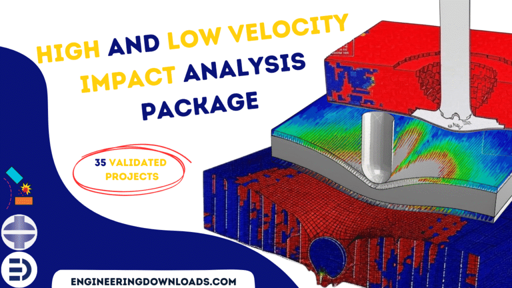
This course offers an in-depth study of impact dynamics and numerical simulation using Abaqus. It is designed to provide students, researchers, and practicing engineers with both theoretical understanding and practical skills in modeling a wide range of impact scenarios. Through systematically structured examples, participants will learn to model and analyze high-velocity and low-velocity impacts on various materials and structures, including ceramics, metals, composites, polymers, reinforced concrete, protective panels, and fluid-structure systems.

The course emphasizes:

  • Fundamental principles of impact mechanics and material behavior under dynamic loading.

  • Practical simulation techniques for setting up impact problems in Abaqus.

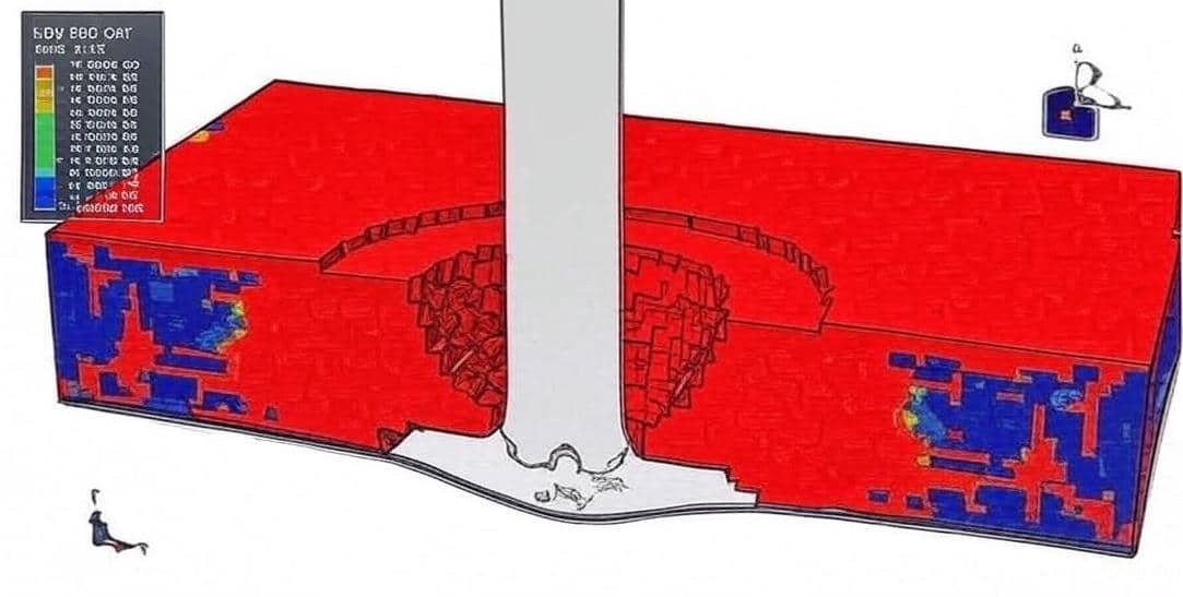
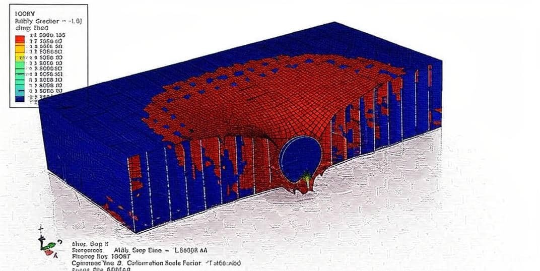
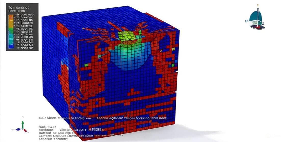
  • Advanced applications, including ballistic impacts, multi-layered armor systems, fluid cavity interactions, and reinforced structural components.

  • Comparative studies of different materials and structural configurations to evaluate performance under impact loading.

By working through over 35 detailed case studies, participants will gain hands-on experience with real-world problems, ranging from projectile penetration and ballistic resistance to low-speed structural impacts and repeated load scenarios. The course thus bridges the gap between theoretical knowledge and engineering practice, preparing learners to apply advanced finite element modeling techniques to research, design, and industrial problem-solving in the fields of aerospace, defense, civil, and mechanical engineering.

Course Content

Example 1: Cold spray process of steel particles on the Inconel surface-HVI
In this lesson, the cold spray process of steel particles on the Inconel surface-HVI is studied. The steel particle is modeled as a three-dimensional solid part. The Nickel-Chromium(Inconel) part is modeled as a three-dimensional solid part. A numerical model for the impact of the steel ball on the surface of Inconel targets was developed by the finite element method using the ALE method. The plastic deformation of the target specimen was simulated using the J–C plasticity model. In addition, the steel ball was modeled as elastic and Johnson-Cook plasticity. The thermal properties for both parts because of the temperature change during the simulation. A dynamic, Temp-Disp, Explicit solving procedure is used to model the relation between stress and temperature during the simulation. The surface-to-surface contact with contact properties like friction is used. The movement of the target was constrained in three directions. The initial velocity is assigned to the steel projectile. The arbitrary Lagrangian-Eulerian (ALE) is considered to refine the mesh during the simulation.

  • Abaqus files
  • Video
    00:00
  • Documents

Example 2: Modeling of High-Velocity Impact on a Ceramic-Steel Plate
In this section, the modeling of high-velocity impact on a Ceramic-Steel Plate is investigated. The steel projectile and steel plate have been modeled as a deformable part, and for the material model, ductile with shear damage coupled with damage evolution has been used. For the ductile damage evolution of the silicon plate, Drucker-Prager plasticity with hardening is coupled with the Us-Up equation for the fracture zone; the JH2 material model can also be used. A dynamic explicit procedure is appropriate for this type of analysis.

Example 3: Simulation of the High-Velocity Impact of a Steel Rod on a ceramic plate reinforced with the composite
In this case, the simulation of the High-Velocity Impact of a Steel Rod on a ceramic plate reinforced with the composite. To model ceramic behavior under the rapid impact load, JH2, JHB, or a combination of the Drucker-Prager and ductile damage criterion can be used. In this mode, the third case is selected to demonstrate the Abaqus CAE capability for the silicon carbide material model. To model the composite material, the Hashin damage criterion is considered.

Example 4: Analysis of the ball impact on a sports net using the Fluid Cavity Technique
In this lesson, the analysis of the ball impact on a sports net using the Fluid Cavity Technique is done. In this tutorial, to model the gas and its pressure inside the ball, the fluid cavity method is selected. Dynamic explcity step and general contact capability are used. By “fluid-cavity model” we mean explicitly modelling the air region that is trapped/squeezed between the ball and net during impact, so pressure in that cavity (and transient air flows) contribute to forces on the ball and net. This is important when contact times are short and trapped air pressure or flow through the net affects rebound, damping, or net deformation.

Example 5: Rigid ball impact on a Balloon Filled with the gas
In this section, the rigid ball impact on a Balloon Filled with the gas is investigated. For modeling balloon shell elements and for creating an internal gas fluid cavity technique has been used. The Dynamic Explicit procedure is appropriate for this type of analysis, and during the analysis, you can see ball penetration into the balloon, and the balloon gas has resistance against the penetration. By “fluid-cavity model” we mean explicitly modelling the air region that is trapped/squeezed between the ball and net during impact, so pressure in that cavity (and transient air flows) contribute to forces on the ball and net. This is important when contact times are short and trapped air pressure or flow through the net affects rebound, damping, or net deformation.

Example 6: Simulation of the soccer ball’s impact on the water surface
In this case, the simulation of the soccer ball's impact on the water surface is done. The ball is modeled as a shell element with hyper hyperelastic material has been used. internal pressure, external pressure, and the specification of air are modeled as the Fluid Cavity technique. For modeling water, the Eulerian element with the Us-Up equation has been implemented. An explicit procedure is appropriate for this type of analysis, as the impact ball penetrates the water, and the fluid cavity’s pressure and volume change suddenly. By “fluid-cavity model” we mean explicitly modelling the air region that is trapped/squeezed between the ball and net during impact, so pressure in that cavity (and transient air flows) contribute to forces on the ball and net. This is important when contact times are short and trapped air pressure or flow through the net affects rebound, damping, or net deformation.

Example 7: Impact analysis of the water-filled X65 steel pipe
In this lesson, the impact analysis of the water-filled X65 steel pipe is studied. Offshore pipelines are frequently subjected to accidental impact loads, e.g., from anchors or trawl gear. A lot of parameters, including the pipe geometry, material properties, pipeline content, impact velocity, etc. This video has presented Impact Simulation against water-filled X65 steel pipes in ABAQUS by using SPH(Smooth Particle Hydrodynamics). An explicit procedure is appropriate for this type of analysis.

Example 8: Analysis of the Bullet Impact on Multi-Layered Plates
In this case, the analysis of the Bullet Impact on Multi-Layered Plates(Aluminum, Ceramic, Steel) is done. All parts are modeled as three-dimensional solid parts. Ductile and Shear damage with evolution for modeling steel behavior, Johnson-Cook damage and plasticity for modeling aluminium behavior, and Ductile damage coupled with Drucker-Prager plasticity for silicon carbide have been exploited. The Dynamic Explicit procedure is appropriate for this type of analysis.

Example 9: Perforation mechanics of aluminium protective plates subjected to high-velocity impact
In this lesson, the perforation mechanism of an aluminium protective plate subjected to high-velocity impact is studied. This study has been carried out using numerical techniques. The impact-protective capacity of structural components has become a relevant requirement for the automotive and aerospace industries. Both energy absorption and crashworthiness concepts are essential for the development of new vehicles and aircraft. In such applications, design challenges are focused on structural crashworthiness and lightweight vehicles. Accordingly, research on crash worthiness has managed to considerably reduce fatalities by 26% in the USA from 2005 to 2011. The plate was created as a three-dimensional part with Johnson-Cook plasticity and damage.

Example 10: Modeling of the High-Velocity Impact of a Gold Projectile on a Ceramic Target
In this lesson, the modeling of the high-velocity impact of a gold projectile on a ceramic target is studied. In this video Simulation high-velocity impact of a ceramic target with the Johnson–Holmquist material model has been studied. Ceramic materials are commonly used in armor protection applications. In recent years, Johnson, Holmquist, and their coworkers have developed a series of constitutive relations to simulate the response of ceramic materials under large strain, high-strain rate, and high-pressure impacting conditions. In this example, the JHB and JH-2 material models are explored to investigate the penetration velocity of a gold projectile impacting a silicon carbide target. The computed results are compared with the published results given by Holmquist and Johnson. The target material is silicon carbide. This material is very hard and mainly used under compressive load conditions and can only sustain very little tension. Typical applications include bulletproof vests and car brakes due to their high endurance. The strength has a dependence on pressure. In high-speed impact applications, damage to the material plays an important role in the evolution of the strength. The totally failed silicon carbide will not sustain any load. The projectile is gold, which is soft compared to the target material.

Example 11: Ballistic performances of concrete targets subjected to projectile impact
In this section, the ballistic performance of concrete targets subjected to projectile impact is investigated. Concrete is a widely used material in the construction of strategic and important structures such as nuclear containments, bridges, storage structures, and military bunkers. In the present study, perforation experiments and simulations on the finite element code ABAQUS/Explicit have been carried out to understand the behavior of concrete against projectile impact. The constitutive modelling for simulating the ballistic penetration of concrete was carried out using the Holmquist-Johnson-Cook (HJC) material model, which is most suitable for predicting the behavior of concrete under large strains, high strain rate, and high pressure. The HJC model predicts the normalized equivalent strength, σ*, of concrete as a function of pressure and strain rate through a simplistic uncoupled approach taking into account the damage cracking, and compaction. In recent years, Johnson, Holmquist, and their coworkers have developed a series of constitutive relations to simulate the response of ceramic materials under large strain, high-strain rate, and high-pressure impacting conditions. In this example, the JH-2 material model is explored to investigate the penetration velocity of a gold projectile impacting a concrete target. The JH-2 model assumes that the damage variable increases progressively with plastic deformation. The concrete part is modeled as a three-dimensional solid part. The material definition needs some techniques to be created as an input file or VUMAT subroutine. The dynamic explicit step is appropriate for this type of simulation. The contact pair with the contact property is selected. The fixed boundary condition is assigned to the concrete slab. The mesh should be fine at the contact zone. During the analysis, the projectile penetrated the concrete and caused huge damage to the concrete slab.

Example 12: Analysis of the high-velocity impact on a ceramic composite system using the JH2 material model
In this case, the analysis of the high-velocity impact on a ceramic composite system using the JH2 material model is done. Since ceramics are low-density materials with high compressive strength, there is great interest in the application of ceramics for weight-saving armor systems. Although the experimental approach offers the most accurate results, it is expensive and sometimes does not provide detailed information about the highly dynamic event. Recently, three-dimensional computations have been performed routinely since they allow for the investigation of many interesting three-dimensional effects. This video represents computations for impact to metal/ceramic/metal composite plates using a three-dimensional explicit Lagrangian model in ABAQUS.To describe the dynamic behavior of brittle materials, Johnson Johnson-Holmquist (JH2) material model has been used. The Johnson-Cook model for steel plates has been used for plasticity and damage. The Dynamic Explicit procedure is appropriate for this analysis. To consider internal element failure general contact capability, as the edit keyboard change with nodal erosion has been applied.

Example 13: Simulation of the rigid impact on CFRP plates
In this lesson, the simulation of the rigid impact on CFRP plates is studied. The use of composite materials in critical aerospace structures is still limited by their relatively weak mechanical response to impact events. In addition, composite laminates subjected to low velocity impact, such as dropped tools or vehicle impact, exhibit significant internal damage and delamination, with little indication on the impact surface that such damage has occurred, generally referred to in the industry as barely visible impact damage. The projectile is modeled as a three-dimensional discrete rigid part, and for modeling CFRP plates, a three-dimensional space with a continuum shell element has been used. Dynamic explicit is appropriate for this type of analysis. During the impact, the projectile penetrated the CFRP plates and caused damage to them.

Example 14: Modeling of the High-Velocity Impact on an Aluminum Honeycomb Sandwich Panel
In this section, the modeling of the high-velocity impact on an aluminum honeycomb sandwich panel is investigated. Sandwich panels are widely used in lightweight construction, especially in the aerospace industry, because of their high specific strengths and stiffness. In the service life of a sandwich panel, impacts are expected to arise from a variety of causes. Debris may be propelled at high velocities from the runway during aircraft takeoffs and landings. Other examples include tools dropping on the structure during maintenance or even collisions with birds. Visual inspection may reveal little damage on the sandwich panel, but significant damage may occur between the impacted facesheet and the core. Reduction of structural stiffness and strength can occur, and consequently, propagate under further loading. Thus, their behaviour under impact has received increasing attention. Finite element modelling is one popular and cost-effective approach involved in the study of sandwich structures. To attain efficiency in numerical analysis, the core in sandwich structures, which has a large number of cells, is usually replaced with an equivalent continuum model. The sandwich panels are analysed in terms of their effective properties rather than by consideration of their real cellular structure. A number of experimental and analytical techniques have been proposed to predict the effective continuum properties of the core in terms of its geometric and material characteristics. modified the classical laminate theory and applied it to a unit cell to derive the equivalent elastic rigidities for the honeycomb core. However, the theoretical formulation of the effective elastic constants for the core could be tedious or almost impossible if the sandwich construction is too complicated. Even if it is possible, the mathematical derivations for one type of sandwich core might not apply to other types.In this simulation projectile is modeled as three three-dimensional parts with steel material, and the honeycomb with two faceted sheets is modeled as a three-dimensional shell with Aluminium material. Johnson-Cook plasticity and damage have been used for both bodies. A dynamic explicit procedure is appropriate for this type of analysis. The contact between the honeycomb and the facial sheet is considered as perfect contact, and between the projectile and the upper surface, surface-to-surface with contact property has been implied. Because of the projectile's high initial velocity, the deformation and damage on the sandwich panel are clear, and the JC damage parameter is available after the impact.

Example 15: Simulation of the Low-Velocity Impact on S-Glass/Polyester Composite Laminate Plate
In this case, the simulation of the Low-Velocity Impact on S-Glass/Polyester Composite Laminate Plate is done. With the growing use of composites in military, air vehicles, and naval structures, sporting goods, and the power industry, the comprehension of impact mechanisms and dynamic behavior is critical to composite designers and end users. A wealth of knowledge has been published on the dynamic impact response of composite materials and structures. Yet, with continually emerging materials and processes, there is a lack of systematic structure-property-performance relationships that provide guidelines on the dynamic impact behavior of composites. The impact response of materials is generally categorized into low, intermediate, high, or ballistic and hyper velocity regimes. The ability to predict the extent of damage and compression after impact of a composite structure can potentially lead to the exploration of a larger design space without incurring significant time and cost penalties. In this simulation, Numerical investigations of S-Glass/Polyester composite laminate plate under low-energy impact have been conducted. A conventional shell composite layout has been used to define composite layouts with different angles. Impact problems involve strong loading with a complex induced damage. To reproduce and hence analyse the complex phenomena occurring during the impact, numerical approaches are more adapted. The finite element method remains the most commonly adopted method to simulate impact problems in various engineering fields. The Abaqus/Explicit FE code, with its dynamic explicit solver, is well-suited for simulating such problems. The most commonly used in FE simulations of composite materials are layered shells, layered solids, stacked solid elements, and stacked or layered continuum shells. The plate is modelled with material as a lamina with anisotropic elasticity coupled with Hashin’s damage criteria. There are interacting failure criteria where more than one stress component has been used to evaluate the different failure modes

Example 16: Deformation behavior of multi-layered materials(silicon carbide,steel,aluminium,CFRP) under impact load
In this lesson, the deformation behavior of multi-layered materials(silicon carbide, steel, aluminium, CFRP) under impact load is studied. The study of the interaction between two impacting bodies, known as impact dynamics or terminal ballistics, has many crucial applications. Bullet impact on armor, occupant and pedestrian safety during automobile accidents, and tool drop on aircraft wing are a few examples where impact dynamics play an important role. An in-depth understanding of the deformation behavior of materials under impact loading helps not only in designing better products but, more importantly saving human life. Knowledge of material response under impact loading will help in estimating, enhancing, and extending the life and performance of any structure. Impact dynamics broadly depend upon two primary variables, namely the geometry and material of impacting bodies. Most often geometry of the impacting bodies gets dictated by the design parameters other than impact requirements: an aircraft wing has to be of an aerofoil configuration, an armor has to be the shape of the human body with limited thickness to enable mobility in a combat zone, and a bullet has to be of conical shape for effective penetration, and so on. Ultimately, it boils down to the response of material(s), which dictates the performance of the structure under impact loading. Various theories have been proposed to model the average behavior of metals, composites, and ceramics under impact loading. Depending upon their nature, different materials have found their niche domain of application. While ceramic materials are most commonly used as a front layer in armor for protection against bullets and shrapnel due to their high penetration resistance capability, epoxy and epoxy-based composites are ubiquitous in the automobile industry for energy absorption due to their high strain to failure and hyper-elastic nature. Domain-dependent application of materials is the most common solution strategy for any design engineer, and some kind of saturation in material choice has been reached recently in this regard. Nonetheless, it is well understood that these solutions are not extremal, and further performance enhancement in the form of weight reduction and/or a higher level of energy absorption is possible with an intelligent design approach. In this simulation, silicon carbide, steel, aluminium, and three CFRP layouts are used as a sandwich panel under rigid impact

Example 17: Analysis of the depth penetration for alumina ceramics under garnet impact
In this section, the analysis of the depth penetration for alumina ceramics under garnet impact is investigated. The target and projectile were modeled as three-dimensional parts. The JH-2 constitutive model was proposed to describe the response of ceramic materials to large strain rates. The JH-2 constitutive model requires several material constants to completely describe the response of a particular ceramic material. The dimensions of the target were 1000×400×400μm3. The boundary conditions for the target were defined as follows: Nodes impacted by a particle on the top face of the target were set free, while nodes on all the other five exterior faces of the target were fixed. A more refined mesh was used in the vicinity of the impact on the target, while a relatively coarse mesh was applied away from the impact area. The abrasive particle was modeled as a sphere using rigid 3D solid (tetrahedral) elements. A dynamic explicit procedure is appropriate for this type of analysis. The initial velocity is 700 meters per second assigned to the garnet. After the impact, the damage variable is obvious, and the garnet penetrated the target

Example 18: Numerical analysis of the high-velocity impact applied to a reinforced concrete panel
In this case, the numerical analysis of the high-velocity impact applied to a reinforced concrete panel is done. It is well known that concrete is much stronger in terms of compression than in tension. Because of its high compressive strength, and to enhance its tensile strength, tensile reinforcements are added to concrete elements subjected to tensile loading. A concrete material is subjected to static and dynamic loads. The static loads are permanent, whereas the dynamic loads vary over time. Among the dynamic loads, impact loads, which have catastrophic consequences on the structures, are included. An analysis of the impact behavior of reinforced concrete (RC) structures has been of significant interest in recent decades. In the present paper, the impact behavior of a reinforced concrete panel penetrated by a rigid steel ogive-nosed projectile is numerically studied. The concrete material is modeled using the Johnson–Holmquist damage model (JH-2). Several constitutive models have been used for a description of the dynamic behavior of brittle materials under impact loads. In this paper, the Johnson Holmquist damage model (JH-2) is used to analyze the impact behavior of a reinforced concrete panel penetrated by a steel ogive-nosed projectile. JH-2 is the second version of the Johnson–Holmquist (JH-1) ceramic model, which is able to simulate the impact behavior of brittle materials, such as the dilatation, pressure-strength dependence, and strain-rate effects resulting from damage. Materials, such as the dilatation, pressure-strength dependence, and strain-rate effects resulting from damageConcrete is modeled as a three-dimensional part, a beam as a wire, and a bullet as a rigid part. A dynamic explicit procedure is appropriate for this type of analysis. General contact by considering nodal erosion as the input file has been applied. A fixed and symmetric boundary is assigned to the concrete part, and an initial velocity is assigned to the bullet. The fine mesh is a necessity at the contact zone between two parts.

Example 19: Low-Velocity Impact analysis of the Reinforced Concrete Slab Strengthened with CFRP
In this lesson, the low-velocity impact analysis of the reinforced concrete slab strengthened with CFRP is done. In this tutorial Low-velocity impact behaviour of RC slab strengthening with CFRP strips in Abaqus has been investigated. Reinforced concrete slabs are structural members that are commonly used in construction. Slabs are designed by considering the effects of both vertical static and dynamic loads. Impact load is a kind of impulsive dynamic load, which is ignored in the design process of slabs, like other structural members. The behaviour of reinforced concrete slabs under impact loading is an area of research that is still not well understood; however, work in this area continues to be motivated by a broad range of applications. Examples include reinforced concrete structures designed to resist accidental loading scenarios such as falling rock impact; vehicle or ship collisions with buildings, bridges, or offshore facilities; and structures that are used in high-threat or high-hazard applications, such as military fortification structures or nuclear facilities. As a result, considerable work has been undertaken in an effort to develop impact-resistant design procedures and to improve the performance of reinforced concrete structures subjected to impact loads. The concrete slab is modeled as a three-dimensional part with CDP material model, and the CFRP is modeled as a three-dimensional shell part with elastic property coupled with Hashin’s damage, and the bars are modeled as a wire part with elastic-plastic material model. A dynamic explicit step with surface-to-surface contact has been implied. The contact between concrete and CFRP is considered as perfect contact, and the embedded region constraint is used for the bars inside the concrete host.

Example 20: Modeling of the steel-silicon carbide-steel trilayer plate subjected to ballistic impact
In this section, the modeling of the steel-silicon carbide-steel trilayer plate subjected to ballistic impact is investigated. Armor systems containing ceramic components can significantly outperform monolithic metals of equivalent areal density. Their performance depends not only on the intrinsic properties of the constituent materials but also on the relative amounts of ceramic and metal and their spatial arrangement. For applications involving military ground vehicles, the armor must be designed to protect against a range of projectile threats and be lightweight, to maintain vehicle maneuverability, load-carrying capacity, and fuel efficiency. In the present study, numerical simulations with established constitutive laws for the constituent materials are used to investigate the effects of design on the ballistic performance of model composite armors comprising layers of ceramic and metal. Comparisons are made based on equivalent areal density. Two steel plates and a ceramic plate are modeled as three-dimensional parts. To model the steel behavior for plates and the projectile, use elastic. plastic data depend on strain rate, ductile damage with evolution, and shear damage has been used. To model silicon carbide behavior under high strain rate deformation, Johnson-Holmquist-Beissel has been used. The JHB model consists of three main components: a representation of the deviatoric strength of the intact and fractured material in the form of a pressure-dependent yield surface, a damage model that transitions the material from the intact state to a fractured state, and an equation of state (EOS) for the pressure-density relation that can include dilation (or bulking) effects as well as a phase change

Example 21: Analysis of the Low-Velocity Impact on the Reinforced Concrete Beam
In this case, the analysis of the low-velocity impact on the reinforced concrete beam is done through a comprehensive tutorial. In this tutorial Simulation low low-velocity impact on a reinforced concrete beam in Abaqus-Damage investigation has been studied . Reinforced concrete (RC) structures have been widely used for centuries, but the understanding of the impact behavior of these structures against impact loads is still limited. Several design codes based on an equivalent static approach provide general principles for the design of structures under impact loads. The impact force and displacement of RC beams can be predicted by using the common spring-mass models of either single degree of freedom (SDOF) or two DOF. The steel material is modeled as an elastic-plastic material with ductile damage property. The concrete material model is so important, and Abaqus provides some material models in its library, but they are not suitable for predicting damage and failure. In this simulation Johnson-Holmquist material model is used. A dynamic explicit procedure is appropriate for this type of analysis. The beams are used as an embedded region in the concrete host. Surface-to-surface contact with penalty contact behavior is used to define contact.

Example 22: High-velocity impact analysis of a brass projectile on the ceramic-aluminum-glass fiber panel
In this lesson, the high-velocity impact analysis of a brass projectile on the ceramic-aluminum-glass fiber panel is studied. The brass projectile, the ceramic plate, the aluminum plate, and the epoxy-glass layers are modeled as three-dimensional parts. The brass material is modeled as an elastic with Johnson-Cook plasticity and damage, the brass is modeled as an elastic with Johnson-Cook plasticity and damage model, the ceramic is modeled as the Beissel model, and the elastic data with fail stress and Hashin’s damage criterion for epoxy-glass is used. The dynamic explicit step is appropriate for this type of analysis. The Abaqus CAE can’t consider the erosion and internal elements’ failure, so to define these issues input file capability is used to model internal damage and erosion. The contact is defined as a general contact in the input file.

Example 23: Modeling of the Ballistic Performance of Ceramic Composite Armor
In this section, the modeling of the ballistic performance of ceramic composite armor is investigated. The ceramic, titanium, and composite layers are modeled as a three-dimensional solid part. The bullet is modeled as a three-dimensional solid part. The use of lightweight armor systems against ballistic threats is of significance to the development of military weapons, owing to providing a high ballistic protection level and simultaneously increasing the mobility of tanks and other military vehicles. Previously, the widely accepted high-hardness steel appeared to be a potential armor architecture, which provides a sufficiently high ballistic performance. However, it does not significantly improve the structural weight. As the armored technique has developed in recent years, a new type of armor system made of a hard ceramic front plate and an energy-absorbing metal or high tensile strength fibers layer is widely used to defeat armor-piercing projectiles. The front ceramic plate blunts and shatters the impacting projectile, and the back laminate materials absorb the remaining kinetic energy of the projectile and simultaneously support the ceramic and projectile fragments to prevent them from further damage. To model ceramic behavior under high-velocity impact, the Johnson-Holmquist model is used. To model the titanium behavior, the Johnson-Cook plasticity and damage are used to predict the damage zone under the impact. For the epoxy-glass fiber elastic behavior as a lamina type, with failure stress and Hashin’s damage criterion with evolution, is used to consider fiber damage during the impact. The dynamic explicit procedure is appropriate for this type of analysis. The general contact procedure with friction coefficient is used to model contact between all parts and between to composite layers. Damage and cohesive behavior are used to model the separation during the simulation. The contact between the other parts is assumed as perfect.

Example 24: Analysis of the high-velocity impact on the composite panel(Steel-Concrete-Epoxy glass)
In this model, the analysis of the high-velocity impact on the composite panel(Steel-Concrete-Epoxy glass) is presented. The steel projectile is modeled as a cylindrical solid part. The steel plate, as a first layer of the pane, is modeled as a three-dimensional part. The concrete, as a middle plate of the panel, is modeled as a three-dimensional solid part, and the composite layers are modeled as a three-dimensional part with the continuum shell technique. The beam part is modeled as the wire part. The steel material with elastic-plastic behavior is used for the projectile and the first layer of the panel. Ductile and shear damage criteria to predict damage propagation and failure are used. The elastic behavior with the failure stress for the epoxy-glass lamina is used. To consider damage in the composite layouts, Hashin’s damage criterion with damage evolution is used. To model concrete behavior under the high-velocity impact, the JH2 material model is used as the input file. This material model can calculate the damage and failure in the brittle material properly. The dynamic explicit step with a general contact procedure is used. The contact between the steel plate and concrete, concrete and the first layer of the composite is assumed as perfect contact. The cohesive interaction based on the cohesive surface as a contact property with damage data is used among the composite layouts. The beam part is embedded inside the concrete host. The Symmetry boundary is implied for the symmetry surfaces and a fixed boundary for the sides of the panel.

Example 25: Analysis of the repeated impact of the rigid body on the steel box
In this case, the analysis of the repeated impact of the rigid body on the steel box is done. The steel box is modeled as a three-dimensional shell part, and the rigid projectile is modeled as a rigid shell part. The steel material is used for the beam with elastic-plastic behavior. Because of the rigid body velocity, the ductile and shear damage is used to predict damage propagation in the beam. The dynamic explicit procedure is appropriate for this type of analysis. The general contact algorithm with the friction coefficient as a contact property is implied. In the first simulation, after the impact, the stress, strain, and damage are achievable. In the second simulation, the results from the first simulation are imported to the new model as residual stress and strain. After the second simulation, the results can be compared with the previous simulation. In the third simulation or third impact, the results from the second simulation are imported to the new model as an initial condition. By calling the ODB output for each analysis, the result can be placed on the new model.

Example 26: Simulation of the rigid impact on the ultra-high-performance fiber-reinforced concrete slab
In this lesson, the simulation of the rigid impact on the ultra-high-performance fiber-reinforced concrete slab is studied. UHP-FRC is a new class of concrete that has been developed to give a significantly higher material performance in comparison to its concrete counterparts. UHP-FRC exhibits superior mechanical characteristics, including a compressive strength of greater than 150 MPa, high elastic modulus, high elastic limit, a tensile strength in the range of 8–۱۵ MPa, strain hardening in tension, fracture energy of several orders of magnitude of traditional concrete, and high post-cracking capacity. The ultra-high compressive strength of UHP-FRC is achieved by using the optimum combination of very fine aggregates that ensures homogeneity and dense packing. The UHPFRC slab is modeled as a three-dimensional solid part. The bars are modeled as three-dimensional wire parts. The rigid projectile is modeled as a shell part. The Concrete Damaged Plasticity is used to model the UHPFRC slab under the impact load. The CDP model can predict tension and compression damage during the impact. The data were extracted from the reference paper. The steel material with elastic-plastic behavior is selected for the bars. The dynamic explicit step is appropriate for this type of analysis. The general contact algorithm with the contact property is implied to consider all contacts. The bars are embedded inside the concrete host.

Example 27: Modeling of the high-velocity steel bullet impact on ceramic-epoxy Armor
In this section, the modeling of the high-velocity steel bullet impact on ceramic-epoxy Armor is investigated. The 3 alumina layers are modeled as a three-dimensional solid part. The 2 epoxy glue layers are modeled as a three-dimensional solid part. The steel bullet is modeled as a three-dimensional solid part. Because of the symmetry, one quarter of the whole model to reduce the time of the simulation. The Johnson-Cook plasticity and damage model is selected for the steel material because this model can consider high-strain-rate deformation of many materials, including most metals. Abaqus/Explicit provides a dynamic failure model specifically for the Johnson-Cook plasticity model, which is suitable only for high-strain-rate deformation of metals. The data for the steel material is extracted from the reference paper. To model epoxy material, elastic data traction type couple with the Maxs damage criterion is used. The epoxy is considered a cohesive material by definition cohesive section. To model alumina behavior under high velocity impact, Abaqus recommends some material models which are available in Abaqus cae, and some of them need to be written as codes. The dynamic explicit step with a mass scale parameter is appropriate for this type of analysis. The general contact capability with friction as a contact property is selected. The perfect contact is assumed between the alumina and epoxy parts.

Example 28: Analysis of the high-velocity impact of the steel rod on the composite panel(Steel-Ceramic-AFRP)
In this case, the analysis of the high-velocity impact of the steel rod on the composite panel(Steel-Ceramic-AFRP) is done. The steel rod and steel cover are modeled as a three-dimensional solid part. The ceramic part is modeled as a three-dimensional solid part. The Aramid Fiber Reinforced Plastic(AFRP) is modeled as a three-dimensional solid part with four layers. The steel material with Johnson-Cook plasticity and damage is used to model the projectile and the steel cover layer. The Johnson-Cook plasticity model is a particular type of Mises plasticity model with analytical forms of the hardening law and rate dependence. It is suitable for high-strain-rate deformation of many materials, including most metals, and is typically used in adiabatic transient dynamic simulations. To model AFRP composite material, the lamina elastic behavior and Hashin’s damage criterion are selected. Abaqus offers a damage model enabling you to predict the onset of damage and to model damage evolution for elastic-brittle materials with anisotropic behavior. The model is primarily intended to be used with fiber-reinforced materials since they typically exhibit such behavior. Damage initiation refers to the onset of degradation at a material point. In Abaqus, the damage initiation criteria for fiber-reinforced composites are based on Hashin’s theory. To model ceramic behavior, the Johnson-Holmquist-Beissel model is used. The JHB model consists of three main components: a representation of the deviatoric strength of the intact and fractured material in the form of a pressure-dependent yield surface, a damage model that transitions the material from the intact state to a fractured state, and an equation of state (EOS) for the pressure-density relation that can include dilation (or bulking) effects as well as a phase change. The dynamic explicit step is appropriate for this type of analysis. The general contact algorithm is selected to consider all contacts in the contact domain. The perfect contact is assumed between the ceramic-AFRP and the ceramic-steel cover.

Example 29: Simulation of the low-velocity impact on the CFRP-AL Foam-CFRP panel
In this model, the simulation of the low-velocity impact on the CFRP-AL Foam-CFRP panel is done. The CFRP is modeled as a three-dimensional solid part with four different fiber directions. The aluminum foam as a core part is modeled as a three-dimensional solid part. The projectile is modeled as a three-dimensional shell part. Foam core sandwich structures comprising two stiff and strong face sheets separated by a lightweight core show two distinct superiorities that are attractive for many applications. First, the separation of the face sheets by the core increases the moment of inertia of the entire structure with little increase in weight, making them efficient structures for resisting bending and buckling loads. Second, they exhibit excellent energy absorption capability, used for example in armor systems, which rely on the high porosity and compressibility of the foam core. An essential factor for the implementation of foam core sandwich structures in structural components is their impact characteristics because these structures are vulnerable to impact from foreign objects in service. Metal foam structures, due to their impact absorbing properties, could be considered as passive safety systems in transportation, which still have a great potential for development as a way to reduce deaths and injuries, which is also associated with the economic costs and social impacts associated with this problem. To model CFRP material, the elastic data with the failure stress parameter and also Hashin’s damage criterion are selected. To model metal foam behavior under impact load, the Crushable Foam model with hardening is used. The dynamic explicit step is appropriate for this type of analysis. The surface-to-surface contact with friction as a contact property is selected between the rigid projectile and the upper CFRP plate. The cohesive interaction by using stiffness parameters and also damage definition between CFRP sheets and foam core is used.

Example 30: Modeling of the low-energy impact on the RC beam
In this lesson, the modeling of the low-energy impact on the RC beam is studied. The concrete beam is modeled as a three-dimensional solid part. The steel bars and strips are modeled as three-dimensional wire parts. The hammer is modeled as a rigid sphere. Concrete structures are used in a wide variety of civil infrastructure applications, such as buildings and bridges. The structures in service are commonly subjected to a range of extreme loading events, including low-velocity impact loads. To understand the response of concrete structures under the impact, full-scale experiments often provide the most reliable predictions. Such tests, however, require significant time, effort, and investment, which unavoidably limit the number and scope of investigations, especially in the destructive range. As an alternative, numerical studies have received growing attention, owing to the current computational power. Despite the availability of simulation capacity, the accuracy of numerical studies greatly depends on the capability of material models. To model concrete behavior under the low-velocity impact, the Concrete Damage Plasticity Model(CDPM) is used. The model is a continuum, plasticity-based, damage model for concrete. It assumes that the two main failure mechanisms are tensile cracking and compressive crushing of the concrete material. To model reinforcement behavior, the elastic-plastic data is selected. The dynamic explicit step is appropriate for this type of analysis. The surface-to-surface contact with the contact property, as friction is used to define contact between the rigid body and the concrete beam. The embedded region constraint is used for the steel reinforcement in the concrete host.

Example 31: Analysis of the oblique high-velocity impact of an aluminum rod on the ceramic target
In this section, the analysis of the oblique high-velocity impact of an aluminum rod on the ceramic target is investigated. The silicon-carbide target is modeled as a three-dimensional solid part. The aluminum projectile is modeled as a three-dimensional solid part. The study of the interaction between two impacting bodies, known as impact dynamics or terminal ballistics, has many crucial applications. Bullet impact on armor. An in-depth understanding of the deformation behavior of materials under impact loading helps not only in designing better products but, more importantly saving human life. Knowledge of material response under impact loading will help in estimating, enhancing, and extending the life and performance of any structure. Impact dynamics broadly depend upon two primary variables, namely the geometry and material of impacting bodies. The response of metals to applied loading not only depends on strain but also on other parameters such as temperature, pressure, strain rate, etc. The Johnson-Cook (JC) model is a phenomenological model commonly used to predict the material response of metals subjected to high strain rate and impact loading. The JC plasticity and damage are used to model aluminum projectile behavior. Generally, ceramic materials are brittle in nature. They have high compressive strength but low tensile strength and tend to exhibit progressive damage under compressive load due to the growth of microfractures. The dynamic explicit step is appropriate for this type of analysis. Because of the internal failure, the surface-to-surface contact isn’t useful, and instead of the input file capability is used to define a contract that considers the erosion during the impact.

Example 32: Simulation of the High-Speed Impact on a Reinforced Concrete Panel
In this case, the simulation of the high-speed impact on a reinforced concrete panel is presented. The dimensions are extracted from the paper. The concrete slab is modeled as a three-dimensional solid part. The steel reinforcements are modeled as three-dimensional wire parts. The bullet is modeled as a discrete rigid body. The material is used based on the paper information. The concrete Johnson-Holmquist model that is available through a VUMAT code or input file modification is selected to consider damage under the high-velocity impact. To model steel reinforcement, JC hardening and damage are considered. The dynamic explicit step with 0.001 seconds as step time is used. The general contact capability with erosion effect to considered an internal failure as the input code is used.

Example 33: Modeling of the Repeated Impact on the Reinforced Concrete Beam
In this study, the modeling of the repeated impact on the reinforced concrete beam is studied. The concrete beam is modeled as a three-dimensional solid part. The steel rebar and strips are modeled as three-dimensional wire parts. The rigid hammer is modeled as a three-dimensional rigid shell part. The concrete Damaged Plasticity is used to model concrete beams under low-energy impact. This model is a continuum, plasticity-based, damage model for concrete. It assumes that the two main failure mechanisms are tensile cracking and compressive crushing of the concrete material. The tensile and compressive stress and damage are defined to obtain the damage in each impact. The elastic-plastic material model is selected to define steel reinforcements. In this tutorial, three repeated impacts are considered, and for all of them, a dynamic explicit step is used. The steel reinforcements are embedded inside the concrete host. The surface-to-surface contact with the contact property, as friction is selected to define contact between the hammer and the RC beam. The fixed boundary condition is assigned to the beam, and the initial velocity to the hammer. After the first impact, all results such as stress, strain, tensile and compressive damage, reaction force, and … are available. To model the second impact, the results from the first impact are applied to all parts, and then the second impact is applied. To do the third impact, the results from the second impact are applied to all parts, and the third impact is done. During repeated impact, the stress, strain, and damage are increased.

Example 34: Analysis of the rigid impact on the composite panel(CFRP+TPU+AL)
In this section, the analysis of the rigid impact on the composite panel(CFRP+TPU+AL) is investigated. The CFRP part is modeled as a shell part with eight layers. The Thermoplastic polyurethane is modeled as a three-dimensional solid part. The Aluminum part is modeled as a three-dimensional solid part. The projectile is modeled as the rigid shell part. Because of the symmetry, one-quarter of the model is used. To model CFRP behavior under the rigid impact, the elastic property with Hashin’s damage criterion is selected. Damage initiation refers to the onset of degradation at a material point. In Abaqus, the damage initiation criteria for fiber-reinforced composites are based on Hashin’s theory. These criteria consider four different damage initiation mechanisms: fiber tension, fiber compression, matrix tension, and matrix compression. To model aluminum behavior, elastic data with Johnson-Cook hardening and damage is used. Abaqus/Explicit provides a dynamic failure model specifically for the Johnson-Cook plasticity model, which is suitable only for high-strain-rate deformation of metals. To model TPU behavior, the elastic-plastic material model with ductile damage criterion is selected. The dynamic explicit step is appropriate for this type of analysis. The perfect contact is assumed between TPU-AL and TPU-CFRP surfaces. The general contact with the contact property is considered between the rigid body and other parts. The fixed boundary condition is assigned to the outer edges and the symmetry boundaries to the symmetry zones.

Example 35: Simulation of the High-Speed Steel Bullet Impact on a Ceramic-AlFoam panel
In this case, the simulation of the high-speed steel bullet impact on a ceramic-AlFoam panel is done. The steel bullet is modeled as a three-dimensional solid part. The ceramic and aluminum foams are modeled as three-dimensional solid parts. Because of the symmetry conditions, one-quarter of the whole model is selected to reduce the time of the simulation. Damage investigation is the aim of this simulation. To model steel bullet behavior, the elastic-plastic model with ductile and shear damage is used. Two main mechanisms can cause the fracture of a ductile metal: ductile fracture due to the nucleation, growth, and coalescence of voids; and shear fracture due to shear band localization. Based on phenomenological observations, these two mechanisms call for different forms of the criteria for the onset of damage. To model ceramic or silicon carbide material, the Johnson-Holmquist or JH2 model is selected. Ceramic materials are commonly used in armor protection applications. In recent years, Johnson, Holmquist, and their coworkers have developed a series of constitutive relations to simulate the response of ceramic materials under large strain, high strain rate, and high-pressure impacting conditions. The JH-2 model assumes that the damage variable increases progressively with plastic deformation. To model metal foam behavior, the crushable foam hardening and ductile damage criterion is used. A dynamic explicit step with general contact capability is appropriate for this type of analysis. The perfect contact is assumed between the ceramic and aluminum foam plates. The symmetry boundary conditions are assigned to the symmetry zones.

Reviews

Student Ratings & Reviews

No Review Yet
No Review Yet
299,00 590,00
29 people watching this product now!

Material Includes

  • 1- Tutorial videos
  • 2- Abaqus files+ Codes
  • 3- Related documents

Audience

  • 1- Civil Engineering
  • 2- Mechanical Engineering
  • 3- Structural Engineering
  • 4- Aerospace Engineering

Related  Products

See more

Want to receive push notifications for all major on-site activities?