Engineering Downloads

Let’s Learn and Collaborate

Engineering Downloads

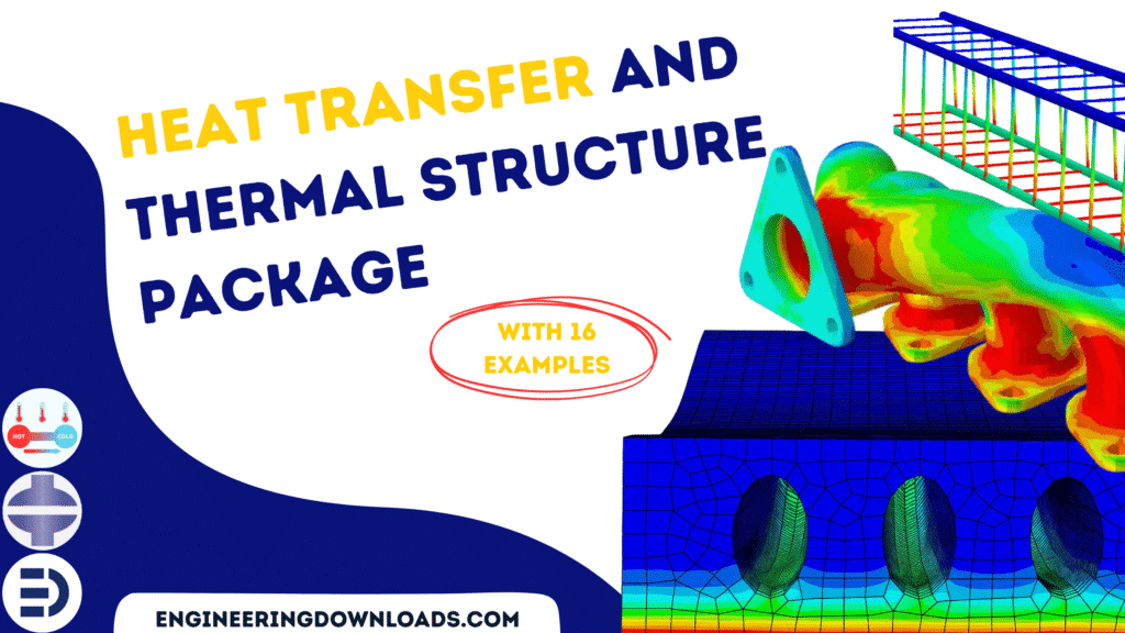
Heat Transfer and Thermal-Structure Package in Abaqus

178,00 320,00
178,00 320,00
20 people watching this product now!

Material Includes

  • 1- Abaqus Files+ Codes
  • 2- Paper+Document
  • 3- Tutorial Videos

Audience

  • 1- Mechanical Engineering
  • 2- Aerospace Engineering
  • 3- Civil Engineering
  • 4- CFD and FSI Engineering
  • 5- Manufacturing Engineering

What You Will Learn?

  • In this course, during 16 advanced tutorials, you'll learn all the details about Heat Transfer and Thermal-Structural analysis in Abaqus.

About Course

Heat transfer analysis is the study of how thermal energy moves from one place to another and the rate at which it occurs. It’s a cornerstone of engineering and science, because nearly every system,  from a coffee mug to a rocket engine, involves heat flow.

Here’s the big picture:


1. What Is Heat Transfer?

  • Heat is energy in transit due to a temperature difference.
  • Once temperatures equalize, there’s no net heat transfer — the system is in thermal equilibrium.
  • In analysis, we care about how much heat moves, how fast, and by what path.

2. The Three Modes of Heat Transfer

  1. Conduction – Heat moves through a solid or stationary fluid because particles or electrons pass along energy.
    • Governed by Fourier’s Law:

      where kk is thermal conductivity.

    • Example: A metal spoon heating up in a cup of tea.
  2. Convection – Heat transfer between a surface and a moving fluid (air, water, etc.).
    • Described by Newton’s Law of Cooling:

      where hh is the convection heat transfer coefficient.

    • Example: Wind cooling your skin.
  3. Radiation – Heat transfer via electromagnetic waves, no medium required.
    • Governed by the Stefan–Boltzmann Law:

      where ε\varepsilon is emissivity, σ\sigma is the Stefan–Boltzmann constant.

    • Example: The Sun warms the Earth.

3. Why We Do Heat Transfer Analysis

  • Design: Ensuring engines, electronics, and buildings operate safely and efficiently.
  • Energy efficiency: Minimizing losses in insulation, power plants, and thermal systems.
  • Temperature control: Preventing overheating or freezing in critical components.

4. How It’s Analyzed

Heat transfer problems can be:

  • Steady-state: Conditions don’t change with time (e.g., a wall at constant temperature difference).
  • Transient: Conditions change over time (e.g., cooling of hot metal in water).

Methods used:

  • Analytical equations (for simple shapes and conditions).
  • Numerical simulations like FEA/CFD for complex geometries.
  • Experimental measurements for real-world validation.

5. Key Parameters in Heat Transfer Analysis

  • Thermal conductivity (k) – material’s ability to conduct heat.
  • Heat transfer coefficient (h) – how well a surface and fluid exchange heat.
  • Thermal diffusivity (α\alpha) – how quickly temperature changes within a material.
  • Biot number, Fourier number, Nusselt number – dimensionless numbers that guide design and scaling.

In this package, you’ll learn all the heat transfer and thermal-structure analysis methods through 16 lectures.  
Course Content

Example-1: Thermal-structural analysis of a 3D cold extrusion process
In this section, the thermal-structural analysis of a 3D cold extrusion process of an aluminum rod in Abaqus is investigated. The cold extrusion process is a common way to reduce the diameter of the metal bar in manufacturing Engineering. The aluminum material is considered an elastic material with plastic data that depends on temperature. The conductivity, specific heat, expansion coefficient, and inelastic heat fraction are used because of the thermally coupled step which is used. A fully coupled temperature-displacement analysis is performed with the die kept at a constant temperature. In addition, an adiabatic analysis is presented using Abaqus/Standard without accounting for frictional heat generation.

  • Abaqus Files
  • Tutorial Video
    24:48

Example-2: Analysis of the steel joint with bolt connectors under fire conditions
In this lesson, the Analysis of the steel joint with bolt connectors under fire conditions is studied. Steel has been at the forefront of efficient construction in the last few years, where it has been widely used in the construction of high-rise buildings, industrial structures, and residential structures. What makes steel one of the most appealing materials in the construction industry is its engineering properties. The elastic-plastic material data depend on the temperature selected for both heat transfer and static analysis. First, the heat transfer model uses conduction and convection as the fire load is applied and the nodal temperatures are extracted. In the second model, the static analysis with bolt load as the pre-load is applied to the bolts, and the fire results from the previous model are considered as the initial state of the model.

Example-3: Thermal analysis of the chip forming process
In this case, the thermal analysis of the chip forming process is studied. Chip formation, a core aspect of machining, is the process by which material is removed from a workpiece in the form of chips during mechanical cutting. This process involves complex interactions of deformation and shearing within a localized area called the shear zone. The dynamic explicit step is coupled to temperature.

Example-4: Fire analysis of an RC beam(concrete+bar)
In this section, the fire analysis of an RC beam(concrete+bar) is studied. The concrete beam and the steel bars are modeled as a three-dimensional solid part. To model concrete behavior under fire conditions, the material should be appropriate, and for that purpose, the specific heat and conductivity depend on the temperature. For the steel bars, specific heat and conductivity are also used. The heat transfer step with a two-hour time duration of the fire is selected. The three types of heat transfer methods are applied. The film condition or fire condition, as a convection method with an amplitude to apply fire temperature, is selected. The radiation is applied to the surfaces of the concrete beam. The conduction is also considered among the steel bars and the concrete beam. The fixed boundary condition is assigned to the two ends of the beam, and the initial temperature to the whole of the model.

Example-5: Thermal and Structural analysis of a steel frame
In this lesson, the Thermal and Structural analysis of a steel frame is done. The steel beam is modeled as an I-shape three-dimensional part. The two boxes are modeled as three-dimensional parts. Steel has been at the forefront of efficient construction in the last few years, where it has been widely used in the construction of high-rise buildings, industrial structures, and residential structures. What makes steel one of the most appealing materials in the construction industry is its engineering properties. The most appealing properties of steel are its strength-to-weight ratio, ductility, and flexibility. Such properties allow designers to build structures such as skyscrapers, which certainly would not have been possible with any other material. Steel can also be prefabricated and shipped to construction sites easily, which is quite beneficial when it comes to meeting the ever-increasing demands of new buildings. Nevertheless, there is a huge downside to using steel as a construction material because of its low resistance to fire when compared to other construction materials such as concrete. Steel loses almost half of its strength when subjected to temperatures that are equal to or greater than 590 °C, which will eventually lead the structure to fail. There are three ways for heat transfer in the fire analysis: Conduction, Convection, and Radiation. All the methods are implied in this tutorial. The proper material data depends on the temperature in both the thermal and structural models used. Proper boundary conditions and mesh are assigned to all parts. In the first model, the fire effect is simulated by a heat transfer model; in the second stage, the static model with fire and mechanical load is considered.

Example-6: Fire and bending analysis of hollow-core concrete slab
In this case, the fire and bending analysis of hollow-core concrete slabs is investigated. Precast/prestressed concrete hollow core (PCHC) slabs with a reduction in self-weight due to longitudinal voids, and without shear reinforcement due to the extrusion method, are most susceptible to shear failure. When subjected to shears, hollow-core slabs commonly failed in a critically brittle manner with the formation of web-shear cracks. In the event of a fire, the shear behavior of PCHC slabs is governed by the temperature-reduced material properties of concrete and strands, and thermal stresses due to a temperature gradient over the depth of the hollow-core sections. All heat transfer methods, such as Conduction, Convection, and Radiation, are used. Both sequential and direct methods can be used to model fire analysis and the bending test. In this model, the direct method is selected.

Example-7: Analysis of RC Beams during Fire Events Using a Fully Coupled Thermal-Stress
In this section, the Analysis of RC Beams during Fire Events Using a Fully Coupled Thermal-Stress is studied. The concrete beam is modeled as a three-dimensional solid part. The steel reinforcements are modeled as wire parts. This tutorial mainly emphasizes the direct coupling technique (DCT), coupled elements, and how to apply it to fire events to fill the existing gap in the literature regarding DCT. As previously mentioned, most numerical simulations for structural elements under different fire scenarios implement either the sequential coupling technique (SCT) or simplified 2D models. This paper aims to study RC beams under fire conditions using DCT, and the same concept can be replicated with other research software packages, such as ANSYS. The proposed methodology was based on a detailed numerical finite element model developed with the ABAQUS program, and DCT was chosen to join the thermal and structural analysis. Generally, two types of coupling techniques are available to connect thermal and structural analyses: SCT or DCT. SCT is based on running a thermal analysis and implementing these results into a structural analysis. On the other hand, for DCT, one model can perform thermal and structural analysis, as coupled elements can express both the thermal and the structural degrees of freedom. Convection loads are used to apply fire loads on different areas of the beam with film coefficients to simulate the desired fire scenario and determine the surfaces in direct contact with the fire. The convection loads vary with time according to the applied fire curve.

Example-8: Thermal-mechanical simulation of Friction Stir Spot welding
In this lesson, the thermal-mechanical simulation of Friction Stir Spot welding by using the ALE method is done. In this simulation, Friction Stir Spot Welding by using the Arbitrary Lagrangian-Eulerian method has been investigated. Aluminium alloy is used as the base material, and the tool is modeled as a rigid body. A dynamic explicit step with some modification to consider the temperature variable has been used. The use of aluminum in the construction of automobiles is on the rise in order to reduce weight and improve fuel efficiency. This raises an important issue on how to join aluminum parts efficiently and economically, and also the need to characterize the mechanical properties of welds. There are many methods available to join aluminum: tungsten inert gas (TIG), metal arc welding (MIG), and resistance spot welding (RSW), to name a few. All the above methods require heating/melting of the aluminum alloy base metal. Other methods that do not require the melting of aluminum alloy base metal are self-piercing riveting (SPR), clinching, and bonding with structural adhesives, to name a few. Spot friction stir welding (SFW), also known as friction stir spot welding (FSSW), is a novel variant of the“linear” friction stir welding (FSW) process developed by Mazda Corporation and Kawasaki Heavy Industries in 2003 as a solid-state joining technique to join aluminum alloys. FSW, which was invented by The Welding Institute (TWI) in 1991, and SFW are promising joining processes that have shown potential practical applications for welding aluminum alloys in the automotive industry.

Example-9: Friction Stir Welding-SPH method
In this section, the analysis of the Friction Stir Welding-SPH method, considering the temperature variable, is studied. Friction Stir Welding (FSW) is a solid-state joining process that utilizes a rotating tool to generate heat and plasticize material, creating a weld without melting. Smoothed Particle Hydrodynamics (SPH) is a numerical method used to simulate the complex material flow and heat transfer involved in FSW. SPH, a mesh-free Lagrangian method, excels at handling large deformations and material mixing, making it suitable for modeling FSW's plastic deformation and bonding mechanisms. PC3DT element is not supported in Abaqus; to overcome that, there are some tricks in the step definition.

Example-10: Analysis of Ballistic Impact in ABAQUS-Thermal analysis
In this lesson, the Analysis of Ballistic Impact in ABAQUS-Thermal analysis of an aluminum plate is done. Ballistic Impact is the study of the behavior of ductile targets subjected to projectile impact. In this work, simulation and analysis are done by using Abaqus/Explicit. Ballistic impact is one of the special cases of impact problems. In such problems, a high force is applied over a short period (called shock loading) when two or more bodies collide. Such a force usually has a greater effect than a lower force applied over a proportionally longer period. This fact makes the study of ballistic impact an interesting and important subject with respect to the safe design of structures. Ballistic impact refers to the phenomenon of a high-velocity impact of a small mass. To have a better approach, the temperature analysis is considered through an Explicit step. The Johnson-Cook validated model is selected to define the aluminum behavior.

Example-11: Analysis of the Cold Spray process using the ALE method
In this case, the Analysis of the Cold Spray process using the ALE method is studied through a practical tutorial. In Cold Spray, powder particles (typically 10 to 40 µm) are accelerated to very high velocities (200 to 1200 m.s-1) by a supersonic compressed gas jet at temperatures below their melting point. Upon impact with the substrate, the particles experience extreme and rapid plastic deformation, which disrupts the thin surface oxide films that are present on all metals and alloys. This allows intimate conformal contact between the exposed metal surfaces under high local pressure, permitting bonding to occur and thick layers of deposited material to be built up rapidly. The deposition efficiency is very high, above 90% in some cases. Whilst thermal spray is widely used in many applications, it uses thermal energy to melt or soften the feedstock. This can cause thermal degradation and partial oxidation of the coating material, which may be undesirable. In this study particle is modeled as three-dimensional with a micrometer size and an AL material which selected for the particle and target. Dynamic Temp Explicit is appropriate for this type of analysis. During the analysis particle and target experienced a huge plastic deformation, and the temperature has proper adoption with experimental data.

Example-12: Thermal and Structural Analysis of the Exhaust Manifold
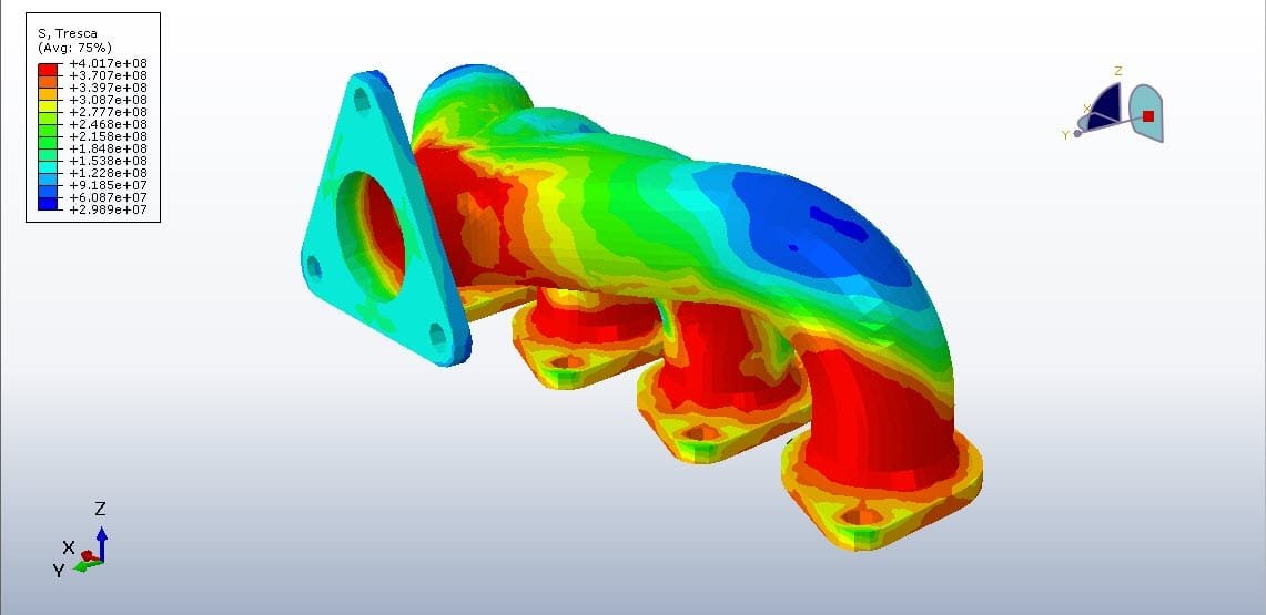
In this lesson, the Thermal and Structural Analysis of the Exhaust Manifold in Abaqus is done. The exhaust manifold is a very essential component of an engine in the field of automobiles, mounted on the cylinder of an internal combustion engine. The gases coming from the cylinder head at different exhaust strokes are collected with minimum backpressure for smooth exhaust. The gases coming from one cylinder at a particular stroke need to discharge smoothly before the gases from other strokes. From multiple pipes, gases were supplied into a common pipe before entering the muffler. The performance of an IC engine depends upon the design of the manifold and the effective emission of combustion products. The exhaust gases coming out of the engine cylinder have a temperature in the range of 800°C with a pressure range from 100kPa to 500 kPa, and the manifold surface experiences 250°C-300°C 300 °C. Therefore the manifold due to temperature gradients exerts a thermal load on the material and causes displacement of the material from the mounted position with the cylinder head. When this thermal load is mapped along with the structural load due to bolt pretension, the stresses will result in both the manifold as well as bolt materials. These stresses should be within the limit for safe design. It is necessary to do the thermo-mechanical analysis during. The simulation has two sections: the first, thermal analysis, and the second, stress analysis. In the first section, through a thermal step, Abaqus calculates the temperature and then, through a static step, Abaqus uses that temperature to consider thermal stress. Convection and Radiation properties are assigned to the internal surfaces. The proper boundary condition for both sections is considered. The mesh should be fine to obtain correct results.

Example-13: Thermal and stress analysis of an engine block
In the present example, the thermal and stress analysis of an engine block is studied. A coupled temperature-stress analysis of an engine block investigates how heat transfer and mechanical stress interact. This analysis is crucial for understanding how temperature variations within the engine affect its structural integrity and long-term performance. By simulating both the thermal and structural behavior, engineers can identify potential failure points due to thermal stress and optimize the engine's design for durability and reliability. In essence, a coupled temperature-stress analysis is a sophisticated simulation that helps engineers design more reliable and durable engine blocks by understanding the complex interplay between heat transfer and mechanical stress.

Example-14: Analysis of a Steel Beam Under Fire and Mechanical Load Conditions
In this model, the Analysis of a Steel Beam Under Fire and Mechanical Load Conditions is investigated. he steel beam is modeled as a three-dimensional solid part, and it can also be modeled as a shell part. Methods for assessing the fire resistance of steel structures are among the best reported in the literature, and they are generally focused on analytical methods. To model thermal behavior of the steel beam under fire conditions in the first analysis, the thermal properties such as specific heat depends on temperature, conductivity depends on temperature, and density are used. In the mechanical analysis, the density, elasticity, and plasticity data that depend on temperature are used. In the fire analysis, the heat transfer step with a long time step to apply the fire condition is selected. The fire condition is considered as a film surface condition, and to apply the fire curvature as a function of the time-temperature, a tabular amplitude is used. The radiation is also applied to the bottom surface of the steel beam. The nodal temperature after the first analysis is imported to the mechanical analysis as an initial condition, and that temperature causes the stress and strain in the steel beam. In the mechanical simulation, the static general step is selected, and mechanical pressure is applied to the top surface of the beam. In the

Example-15: Analysis of Thermal Mixing and Reverse Flow Characteristics in a T-junction using the CFD Model
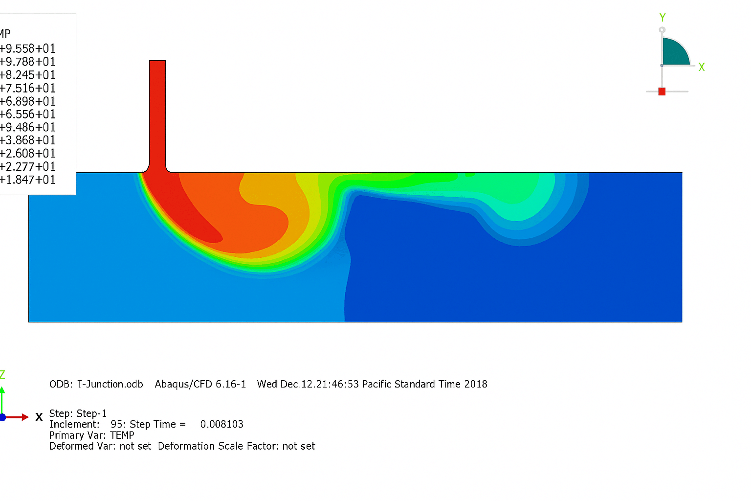
In this section, the Analysis of Thermal Mixing and Reverse Flow Characteristics in a T-junction using the CFD Model is done in Abaqus CFD. T-junctions are commonly used in piping systems and multi-channel networks in various industries, including petrochemical plants, electronic cooling applications, molecular biological processes, power plants, etc. It is crucial to comprehensively understand the thermal–hydraulic characteristics in a T-junction for piping design. Many simulations using computational fluid dynamics (CFD) with different turbulence models have been conducted to investigate the mixing characteristics of T-junctions. studied temperature fluctuations caused by thermal mixing in T-junctions using the large eddy simulation (LES) turbulence model. The results showed that the calculated maximum temperatures were somewhat higher than the measurements. In this simulation, Abaqus CFD has been used.

Example-16: Analysis of thermal stress analysis of arc welding
In this case, the Analysis of thermal stress analysis of arc welding between two pipes by using the DFLUX subroutine is studied. Arc welding is one of several fusion processes for joining metals. By applying intense heat, metal at the joint between two parts is melted and caused to intermix – directly, or more commonly, with an intermediate molten filler metal. Upon cooling and solidification, a metallurgical bond is created. Since the joining is an intermixture of metals, the final weldment potentially has the same strength properties as the metal of the parts. This is in sharp contrast to non-fusion processes of joining (i.e., soldering, brazing, etc.) in which the mechanical and physical properties of the base materials cannot be duplicated at the joint. In this tutorial, steel material for pipes and the DFLUX subroutine to create non-uniform heat distribution have been used. All material data depend on temperature, and for the analysis weld process Displacement Couple with Temperature step is used.

Reviews

Student Ratings & Reviews

No Review Yet
No Review Yet
178,00 320,00
20 people watching this product now!

Material Includes

  • 1- Abaqus Files+ Codes
  • 2- Paper+Document
  • 3- Tutorial Videos

Audience

  • 1- Mechanical Engineering
  • 2- Aerospace Engineering
  • 3- Civil Engineering
  • 4- CFD and FSI Engineering
  • 5- Manufacturing Engineering

Related  Products

See more

Want to receive push notifications for all major on-site activities?