Introduction to Fatigue and Cyclic Loading Modeling & Simulation
1. The Context
Many engineering components, from aircraft wings and automotive crankshafts to bridges and offshore structures — are subjected not to a single static load, but to repeated (cyclic) loads over their lifetime. Even if these loads are well below the material’s ultimate strength, they can cause progressive damage leading to fatigue failure.
This makes fatigue analysis a cornerstone of design for safety, durability, and life prediction.
2. The Concept of Fatigue
- Definition: Fatigue is the progressive structural damage that occurs when a material is subjected to fluctuating stresses and strains over time.
- Failure Mode: It’s typically brittle in appearance (even in ductile metals), initiated by microscopic cracks that grow with each load cycle until catastrophic failure.
- Stages of Fatigue:
- Crack initiation at stress concentrators (surface defects, notches, inclusions).
- Crack propagation under cyclic loading.
- Final fracture when remaining cross-section can no longer carry the load.
3. Cyclic Loading
- Loading Types: Can be fully reversed (tension-compression), pulsating, or random spectrum loading.
- Characterization: Cyclic loads are often described by stress amplitude, mean stress, and load ratio R=σmin/σmax
- Real-world Complexity: Load histories can be irregular (e.g., variable amplitude loading from road conditions or wind gusts), requiring cycle counting methods like Rainflow Counting.
4. Modeling Approaches
- Stress-Life (S–N) Approach
- Empirical relationship between cyclic stress amplitude and number of cycles to failure.
- Suitable for high-cycle fatigue (low stress, elastic deformation).
- Often uses Basquin’s equation and correction for mean stress (Goodman, Gerber).
- Strain-Life (ε–N) Approach
- Captures low-cycle fatigue (high stress, plastic deformation).
- Uses Coffin–Manson relation for plastic strain and Basquin for elastic strain.
- Fracture Mechanics Approach
- Models crack growth rate using Paris’ Law or similar relations.
- Useful for predicting remaining life after a crack is detected.
- Multiaxial and Variable Amplitude Loading Models
- More advanced methods account for multi-directional stresses and realistic service loading histories.
5. Simulation Tools & Techniques
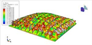
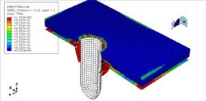
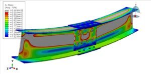
- Finite Element Analysis (FEA):
- Provides local stress/strain fields under cyclic loads.
- Often coupled with fatigue life prediction software (e.g., nCode, fe-safe, Ansys nCode DesignLife).
- Load Spectrum Simulation:
- Time histories from real-world measurements (road profiles, flight data) are processed into equivalent stress cycles.
- Damage Accumulation Models:
- The most common is Miner’s Rule (linear damage accumulation).
- Nonlinear models attempt to account for load sequence effects.
6. Purpose of Modeling & Simulation
- Predict component life before physical prototypes are built.
- Optimize design for weight, cost, and durability.
- Reduce the need for expensive full-scale fatigue testing.
- Ensure safety and regulatory compliance.
7. Challenges & Considerations
- Material variability and microstructure effects.
- Surface treatments, residual stresses, corrosion, and temperature influence.
- Accurate representation of load spectra and boundary conditions.
