Engineering Downloads

Let’s Learn and Collaborate

Engineering Downloads

Earthquake and Seismic Analysis Package

216,00 489,00
216,00 489,00
29 people watching this product now!

Material Includes

  • 1- Abaqus Files
  • 2- Document
  • 3- Tutorial Videos

Audience

  • 1- Civil Engineering
  • 2- Structural Engineering
  • 3- Soil and Geotechnical Engineering
  • 4- Mechanical Engineering

What You Will Learn?

  • During the earthquake and seismic analysis package, you'll learn everything that you need, such as seismic analysis for structures like tanks, vessels, dams, steel frames, steel buildings, dampers, airy containers, composite vessels, tunnels, Masonry walls, and many others, and besides them, you'll learn more about acoustic model, CEL method, ground motion, infinite element, and ...

About Course

Introduction to Earthquake and Seismic Analysis

An earthquake is the sudden release of energy stored in the Earth’s lithosphere, causing seismic waves that shake the ground. These events are usually triggered by the movement of tectonic plates along faults, volcanic activity, or other stress accumulations in the Earth’s crust. Depending on their magnitude and depth, earthquakes can cause significant damage to structures, lifelines, and communities.

The study of earthquakes involves understanding their generation, propagation, and impact. Seismologists analyze ground motion data, fault mechanics, and wave behavior to better predict earthquake risks and improve safety measures.

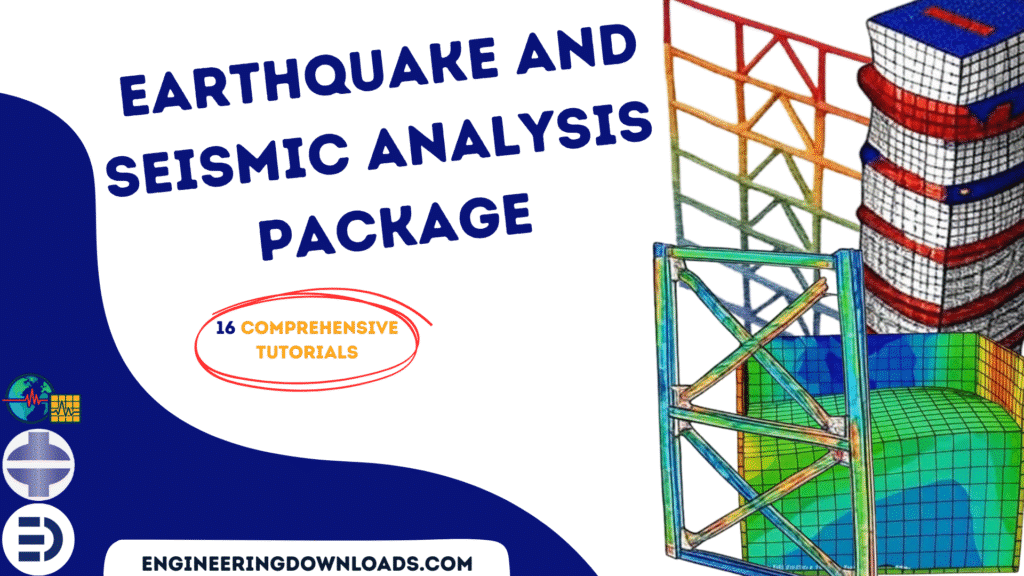
This package includes 16 tutorials that cover many subjects such as dam, foundation, column, beam, masonry wall, steel structure, steel frame, and …

Seismic Analysis

Seismic analysis refers to the process of evaluating how structures and systems respond to earthquake ground motions. It plays a critical role in earthquake engineering, ensuring that buildings, bridges, dams, and lifeline infrastructures remain safe and functional during and after seismic events.

There are several approaches to seismic analysis, including:

  • Equivalent static analysis – a simplified method suitable for regular, low-rise structures in regions of low-to-moderate seismicity.
  • Response spectrum analysis – evaluates structural response across different frequencies of vibration.
  • Time history analysis – involves direct simulation of structural response using recorded or synthetic ground motion data.

Seismic Simulation

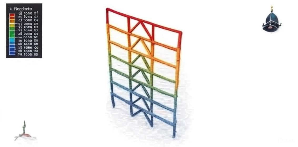
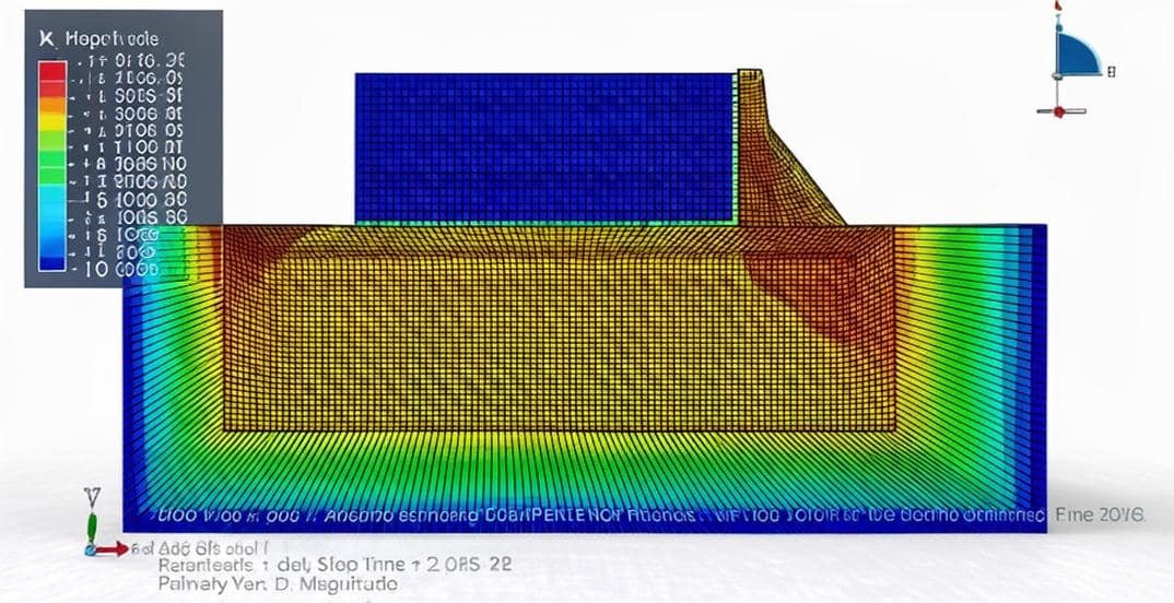
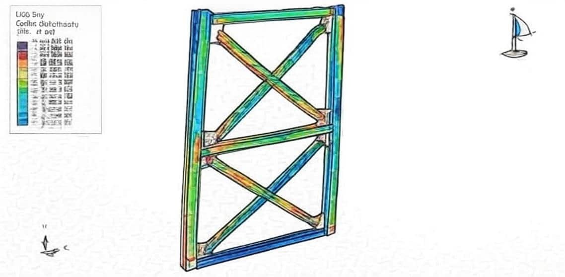
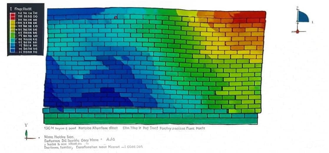
Seismic simulation uses computational tools to model and replicate the effects of earthquakes on structures and geotechnical systems. Advanced finite element software, such as Abaqus, is often used to carry out nonlinear dynamic simulations, soil-structure interaction studies, and performance-based earthquake engineering.

Key purposes of seismic simulation include:

  • Predicting the behavior of structures under real or hypothetical earthquake scenarios.
  • Identifying weak points and failure mechanisms.
  • Assisting in the design of earthquake-resistant systems.
  • Supporting disaster preparedness and mitigation strategies.

In modern engineering, earthquake analysis and simulation form the backbone of resilient infrastructure development. By integrating seismology, structural engineering, and computational modeling, researchers and engineers can reduce risks, enhance safety, and improve disaster response strategies.

Course Content

Example-1: Crack growth analysis in the Koyna dam under earthquake load
In this lesson, the crack growth analysis in the Koyna dam under earthquake load is studied. In this example, we consider an analysis of the Koyna dam, which was subjected to an earthquake of magnitude 6.5 on the Richter scale on December 11, 1967. The example illustrates a typical application of the concrete damage based on traction separation laws. The dam is modeled as a two-dimensional part with damaged material. Before the dynamic simulation of the earthquake, the dam is subjected to gravity loading and hydrostatic pressure. In the Abaqus/Standard analysis, these loads are specified in two consecutive static steps, using a distributed load with the load type labels GRAV (for the gravity load) in the first step and HP (for the hydrostatic pressure) in the second step. To model physical crack growth XFEM procedure has been selected

  • Abaqus Files
  • Tutorial Video
    00:00

Example-2: Water sloshing of the buried concrete tank in the soil subjected to earthquake loading
In this section, the water sloshing of the buried concrete tank in the soil subjected to earthquake loading is investigated. Earthquake brings huge losses in the development of human society repeatedly, which is one of the most serious natural disasters facing humanity. The world’s earthquake occurs about 500 million times every year, of which magnitudes 6 and above are about 100 to 200 times, and magnitudes 7 and above are about 18 times. Earthquake loads have usually been considered in their design, but the analyses have been based on a simplified theory developed for retaining walls with the wall top at the ground surface and the foundation assumed to be rigid. When the structure is constructed below the surface in deep soil layers, these simplified methods have obvious limitations. The tank, soil, and water are modeled as a three-dimensional solid part. To model soil behavior, Mohr-Coulomb plasticity and elasticity are used. For the water Us-Up equation of state and for the concrete CDP model are used. The dynamic explicit step is used to investigate water sloshing during an earthquake. The surface-to-surface contact between water and tank, without a zero value for the friction coefficient, is used. The contact between soil and concrete is assumed as a surface-to-surface contact with a contact property.

Example-3: Analysis of the Seismic Behavior of a Prefabricated Semirigid Steel Frame with an X-shaped Brace
In this case, the analysis of the Seismic Behavior of a Prefabricated Semirigid Steel Frame with an X-shaped brace is done. The steel column and beam are modeled as three-dimensional parts. The steel plate, as stiffeners and braces, is modeled as three-dimensional parts. Vigorously promoting and developing steel structure buildings can not only relieve the excess capacity of the steel industry but also promote the greening, industrialization, and informatization of buildings, thus realizing the transformation and upgradation of traditional industries. The development of steel structure houses is the key to promoting the application of steel structures. At present, the connections between beams and columns in steel frames all adopt either rigid connections or hinged connections. However, due to the limited stiffness of the connections used in actual engineering, it is difficult to form an ideal rigid or hinged connection, so a semirigid connection objectively exists. -The design concept of two seismic fortification lines is in line with the modern seismic design concept. Therefore, this type of structure has been widely used in multistory steel-structure buildings. By combining the X-shaped concentrically braced frame with the semirigid steel frame, it is possible to form a prefabricated semirigid steel frame with X-shaped concentric braces. Braces can compensate for the weakness of lateral stiffness in the semirigid steel frame and produce satisfactory ductility and energy dissipation capacity, which shows promise for use in engineering applications. The proper material model appropriate for cyclic and seismic loading for the steel material is selected. The general static step with some changes in the convergence model is selected. The weld connection between the column and stiffener plates is used. Contact property as friction is considered.

Example-4: Analysis of the CFRP for seismic strengthening of shear-controlled RC columns
In this lesson, the analysis of the CFRP for seismic strengthening of shear-controlled RC columns is studied. The concrete column is modeled as a three-dimensional solid part, the steel reinforcements are modeled as a three-dimensional wire part, and the CFRP is modeled as a shell part. Recent post-earthquake surveys revealed the high vulnerability of existing Reinforced Concrete (RC) structures, often designed for gravity loads only, even to moderate seismic events. Indeed, the lack of proper seismic detailing and a wrong shear-flexure hierarchy often leads to columns' brittle failures due to shear before attaining the flexural yielding. Furthermore, short and wall-like RC columns are commonly subjected to such a brittle failure, governed by concrete diagonal compression failure. To prevent premature brittle failures of existing RC columns, the use of Externally Bonded Reinforcement (EBR) made of Fibre Reinforced Polymer (FRP) strips has been recognized as a reliable and cost-saving strategy for increasing members' lateral strength capacity. Plenty of researchers focused attention on the shear strengthening of RC beams, mainly due to gravity loads. Even though post-earthquake observed shear failures in columns are more diffuse than shear failures of beams. To model seismic behavior of concrete, the Concrete Damaged Plasticity(CDP) material is selected to consider tension nd compression damage. The CFRP reinforcement is modeled as an elastic material that can be damaged model is also available. The general static step is appropriate for this type of analysis. All contact, constraints, cyclic loading boundary, and meshes are assigned

Example-5: Water sloshing modeling in the cylindrical tank under earthquake loading with the Acoustic method
In this section, the water sloshing modeling in the cylindrical tank under earthquake loading with the Acoustic method is investigated. Besides the seismic loading analysis, the frequency model is used to extract the frequency of the tank and the acoustic water part. The storage steel tank is modeled as a three-dimensional shell part. The water is modeled as a solid, and the water’s upper surface is modeled as a shell part. Sloshing is a violent, resonant fluid motion in a moving tank. When a fluid moves and interacts with its container, the dynamic pressures of such an interaction may cause large deformation in the container wall and supporting structure. Most of the work has been done on rectangular tanks. Both the dynamic explicit and implicit can be used. The proper interactions are considered among the parts. The mechanical boundary is assigned to the tank, and the acceleration is applied as a seismic load.

Example-6: Analysis of a steel building with axial dampers
In this lesson, the analysis of a steel building with axial dampers is studied. The steel building, including its beams, columns, and connectors, is modeled as wire parts. In the present scenario, the whole world is susceptible to the damaging effects of seismic hazards. Hence, a detailed study and investigation of the seismic behavior of structures is necessary throughout the construction process. In the case of high-rise buildings, the effect of lateral forces has to be given due consideration because the exceedance of the lateral loads could lead to undesirable vibrations, stress, and instability in the buildings. Steel dampers are components used in building structures to reduce vibration and energy generated by dynamic loads such as earthquakes. Several factors affect the effectiveness of steel dampers in reducing energy, including the cross-sectional area, mass distribution, cross-sectional geometry, and material stiffness. Earthquakes have always been taken into consideration when constructing an engineering structure; other branches of civil engineering have sprung up to study the effects of earthquakes and the best possible ways to prevent structural failure. The effects of an earthquake on a structure can cause loss of life and investment. An expensive engineering structure can be destroyed in an instant due to the occurrence of an earthquake. Therefore, engineers need to make structures resistant to earthquakes and other natural forces to prevent loss of life and investment. In seismic structure upgrading, one of the lateral force reductions caused by the earthquake is the use of dampers. During an earthquake, high energy is applied to the structure. This energy is applied in two types, kinetic and potential (strain), to the structure, and it is absorbed or amortized. The dynamic implicit step is selected to apply the earthquake load, the proper connection among all parts is considered, and he axial damper is generated on each floor

Example-7: Sequential embankment construction and earthquake analysis
In this section, the sequential embankment construction and earthquake analysis are investigated. The two-dimensional space is used. The model contains two parts, embankment and soil. The embankment was separated into some regions to make sequential construction, and the soil was separated into two sections: dry and saturated. The elastic-plastic material with permeability behavior is used for the soil. In this tutorial, eight steps are used. In the first step, the Geostatic step is implied to make equilibrium between the elements of the soil. In the next five steps, the soil step is used to make embankment construction. After the consolidation is considered a soil step with a long-term period. In the end, the dynamic implicit step to apply earthquake acceleration is used. In the interaction, the model change is used to apply the embankment layers in each step. The body force is applied to the dry and saturated soil in step one. The body force is considered for each layer of the embankment at the specific step. The proper boundary condition is assigned to the bottom and the sides of the soil, and these boundaries are edited in the earthquake step. The pore fluid boundary is applied to the dry soil with a zero value. The Geostatic stress, as the predefined field, is assigned to the dry and saturated soil. The earthquake load, as two vertical and horizontal accelerations, is applied to the model to investigate the stress distribution after embankment construction and the earthquake phenomenon.

Example-8: Earthquake analysis of a concrete tunnel
In this case, the earthquake analysis of a concrete tunnel is done. The tunnel industry has considered that tunnels, especially tunnels in rock, are naturally resistant to earthquake action, including faulting, shaking, deflection, and ground failure. As the number of case histories of tunnels subject to earthquake action has increased, the industry has started to recognize that, although tunnels in rock have good resistance against earthquakes generating peak ground accelerations (PGA) lower than 0.5 g, it is important to include the dynamic forces and displacements generated by seismic ground motions in the design process to obtain a more reliable design. The soil and concrete tunnel are modeled as a two-dimensional part. CDP(concrete damage plasticity) for concrete and Mohr-Coulomb plasticity for soil have been used. This simulation has been done in three stages. In the first stage the the soil weight is assigned to the soil part. In the second step, the gravity is assigned to all parts, and in the third step, the earthquake acceleration is applied to the assembled part. Geo stress is the other parameter which assigned to the soil by using predefined field

Example-9: Analysis of the masonry wall under seismic load
In this lesson, the analysis of the masonry wall under seismic load is studied. The recent rise in terrorist activities around the globe has attracted the attention of engineers and scientists towards the vulnerability of buildings and infrastructure to blast loads. The consequent effects of these loads may range from minor damage to structural collapse, accompanied by huge loss of life. The masonry, which is the oldest and the most widely used building material, either in masonry buildings or in the form of infill walls in reinforced concrete (RC) framed buildings, suffers the most damage. Even if there is no complete damage or structural collapse, the flying debris may cause significant loss of life or injuries. As a result, efforts were made by several investigators to examine feasible methods for strengthening masonry walls in order to enhance their resistance to blast loads. Although several techniques have been tried but one of the most popular methods of retrofitting unreinforced masonry (URM) walls is the application of fiber-reinforced polymers (FRP) to its surface. As the blast causes a pressure to be exerted on the surface of a wall, the flexural resistance of the wall needs to be enhanced. In this simulation, two cases have been investigated: the first simulation of earthquake load over the masonry wall, and the second simulation masonry wall under pressure and transverse load.

Example-10: Sloshing analysis of a tank containing water under earthquake load
In this section, the sloshing analysis of a tank containing water under earthquake load is investigated. The water and tank are modeled as three-dimensional deformable parts. Elastic plastic material for a concrete tank and viscosity with the Us-Up equation for water has been used. Earthquake load is applied as a dynamic explicit step with a fifty-five-second duration. To model water sloshing Lagrangian approach is implemented. During the earthquake, water began sloshing and a water wave collided with the tank wall and causing stress in it.

Example-11: Water sloshing in the concrete tank under earthquake load
In this case, the water sloshing in the concrete tank under earthquake load is presented. Concrete tank is modeled as a three-dimensional shell with elastic material and water as an Eulerian part with the Us-Up equation. An explicit procedure is appropriate, and a fifty-five-second time period has been applied. To define the water initial volume, the volume fraction tool has been implemented. During the analysis, water goes through the vessel, and sloshing occurs under earthquake load.

Example-12: Earthquake analysis of the airy water container
In this section, the earthquake analysis of the airy water container is investigated. The container is modeled as three three-dimensional shells with steel material, and for modeling the legs beam element with steel material has been used. Water is modeled as a three-dimensional Eulerian part, and for modeling its behavior Us-Up equation has been implemented. An explicit procedure is appropriate for this type of analysis and earthquake load, as horizontal acceleration is applied for one and a half seconds to the base of the structure.

Example-13: Two-dimensional tunneling and earthquake analysis
In this lesson, the two-dimensional tunneling and earthquake analysis are studied. In geomechanics and structural engineering, tunneling analysis refers to simulating the excavation of underground tunnels and their interaction with the surrounding soil or rock. A two-dimensional (2D) model simplifies the problem by considering either: Plane strain conditions (most common): assumes the tunnel extends infinitely in the longitudinal direction, so deformation is only in the cross-sectional plane. Axisymmetric conditions: used for circular tunnels around a central axis (e.g., shafts, bored tunnels). This makes 2D tunneling a computationally efficient first step before moving to 3D models. Two-dimensional tunneling analysis in Abaqus involves creating a cross-sectional model of the tunnel under plane strain or axisymmetric assumptions, applying geostatic stresses, simulating staged excavation with possible lining installation, and analyzing the soil–structure interaction.

Example-14: Sloshing analysis of an airy CFRP composite tank
In this case, the sloshing analysis of an airy CFRP composite tank is done. Airy Carbon Fiber Reinforced Polymer (CFRP) composite tanks are widely used in aerospace, automotive, and energy storage applications due to their high strength-to-weight ratio, corrosion resistance, and durability. However, when these tanks contain liquids (such as fuel or cryogenic fluids), they are subjected to dynamic loads from seismic activity and fluid sloshing, which can affect structural integrity. Seismic and sloshing analysis of an airy CFRP composite tank requires a multidisciplinary approach combining structural dynamics, fluid mechanics, and material science. Advanced simulation techniques (CEL, SPH, Acoustic CFD), along with experimental validation, are essential for ensuring safety and performance in critical applications

Example-15: Analysis of the gravity dam in interaction with water and soil under earthquake load
In this section, the analysis of the gravity dam in interaction with water and soil under earthquake load is investigated. All parts are modeled as two-dimensional, and for dam CDP material, for soil Mohr-Coulomb, and for water Acoustic property as Bulk Modulus, has been used. An infinite element for soil far from the foundation was created. A dynamic implicit step is appropriate for this type of analysis, and the time of this simulation was 10 seconds, and the acceleration that comes from the earthquake was applied to the depth of the soil.

Example-16: Seismic analysis of geosynthetic-reinforced soil
In this case, the seismic analysis of geosynthetic-reinforced soil in Abaqus is presented. The soil is modeled as a two-dimensional part. The geosynthetic is modeled as a wire part. Geosynthetic-reinforced soil (GRS) structures perform well during strong earthquakes due to their flexibility and integrity. This is evident from the 1994 Mw 6.8 Northridge earthquake, with recorded peak ground acceleration (PGA) values greater than 0.60 g. The variables associated with seismic ground motions, soil properties, and reinforcement parameters are full of uncertainties and bring threats to the dynamic stability of GRS structures. In the first model, the geosynthetic is placed in the soil, and in the second model, the earthquake load is applied to the soil with geosynthetic reinforcement. In the first model, the general static step is considered, and in the second model, the implicit step is considered.

Reviews

Student Ratings & Reviews

No Review Yet
No Review Yet
216,00 489,00
29 people watching this product now!

Material Includes

  • 1- Abaqus Files
  • 2- Document
  • 3- Tutorial Videos

Audience

  • 1- Civil Engineering
  • 2- Structural Engineering
  • 3- Soil and Geotechnical Engineering
  • 4- Mechanical Engineering

Related  Products

See more

Want to receive push notifications for all major on-site activities?