Engineering Downloads

Let’s Learn and Collaborate

Engineering Downloads

DEM and SPH Analysis Package

218,00 497,00
218,00 497,00
19 people watching this product now!

Material Includes

  • 1- Abaqus Files
  • 2- Documents
  • 3- Tutorial Videos

Audience

  • 1- Mechanical Engineering
  • 2- Civil Engineering
  • 3- Structural Engineering
  • 4- Aerospace Engineering

What You Will Learn?

  • During this course, you'll learn all about DEM and SPH analysis and modeling in Abaqus through 20 practical and comprehensive tutorials. The subjects, like Impact analysis using the DEM method, non-Newtonian water flow, granite stone, hydroforming process, cold spray, waterjet cutting, abrasive waterjet, explosion, bird strike, concrete, ceramics, composites, soil, FSW, and many other controversial things.

About Course

Introduction to DEM and SPH Analysis

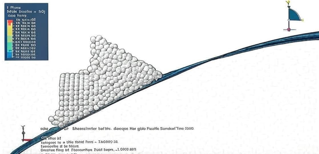
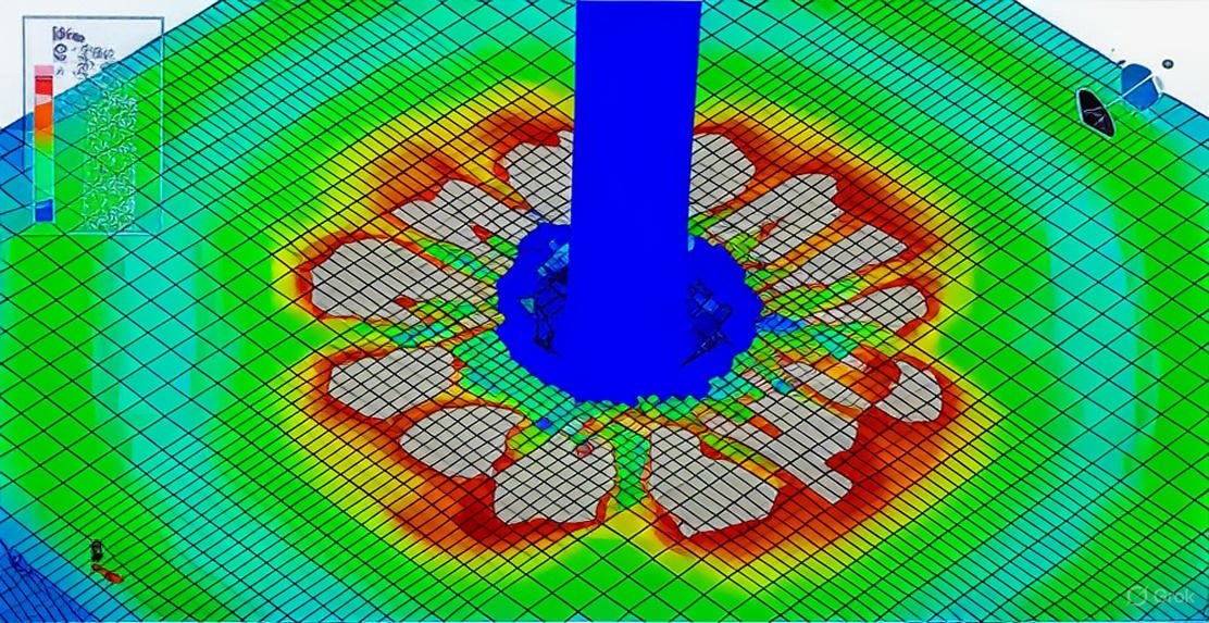
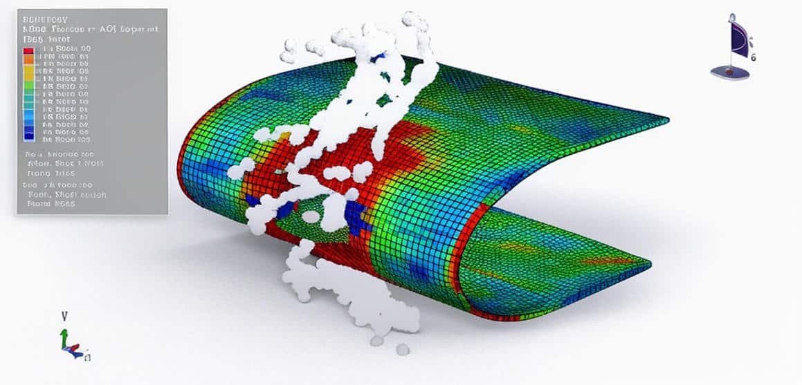
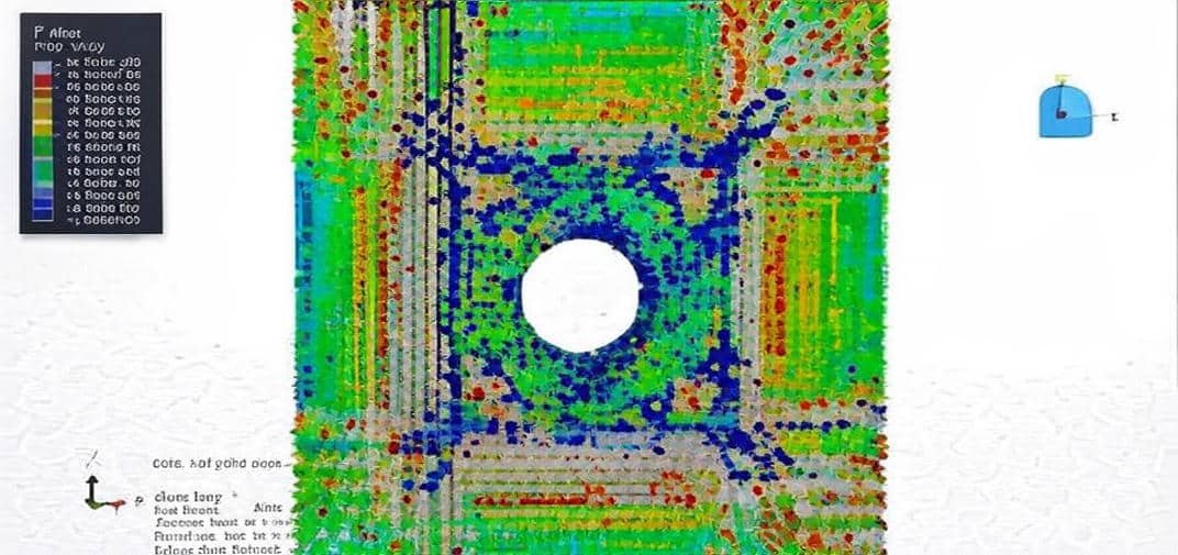
The Discrete Element Method (DEM) and Smoothed Particle Hydrodynamics (SPH) are powerful numerical methods used to simulate and analyze systems involving discrete particles, fluid flows, and their interactions with solid structures. These methods have become essential tools in engineering, geomechanics, materials science, and Multiphysics research.

This package includes 20 tutorials that cover the DEM and SPH analysis in Abaqus. The examples include impact, explosion, non-Newtonian flow, waterjet, hydroforming, cold spray, bird strike, and FSW simulation.

  1. Discrete Element Method (DEM)

    • DEM is used to model the motion and interaction of a large number of particles, such as powders, grains, rocks, or pellets.
    • Each particle is treated as a discrete entity, and Newton’s laws of motion govern their dynamics.
    • DEM captures contact forces, friction, cohesion, and breakage, making it ideal for simulating granular flow, soil mechanics, rock mechanics, and bulk material handling.
  2. Smoothed Particle Hydrodynamics (SPH)

    • SPH is a mesh-free, particle-based method for simulating fluids and highly deformable continua.
    • Instead of solving fluid equations on a fixed grid, SPH uses particles that carry mass, momentum, and energy.
    • It is widely used for problems involving free surfaces, multiphase flows, large deformations, fragmentation, and fluid–structure interaction.
  3. Coupled DEM–SPH Simulation

    • Many real-world problems involve both granular particles and fluids (e.g., slurry transport, landslides, debris flows, and powder-liquid mixing).
    • Coupling DEM with SPH allows for accurate modeling of particle-fluid interactions, where DEM tracks the solid particles and SPH simulates the surrounding fluid.
  4. Simulation in Abaqus

    • Abaqus provides integrated DEM and SPH packages that allow engineers and researchers to perform advanced Multiphysics simulations.
    • DEM in Abaqus captures particle interactions and dynamics.
    • SPH in Abaqus allows mesh-free modeling of fluids and deformable solids.
    • Together, they enable comprehensive simulation of complex processes such as erosion, wear, impact, fluidization, and multiphase material behavior.

In summary, DEM and SPH simulation and analysis provide robust tools for studying complex particle and fluid systems that are difficult or impossible to capture with traditional continuum or grid-based methods. Their integration in software such as Abaqus makes them highly accessible for practical engineering and scientific applications.

Course Content

Example-1: Analysis of the sand impact on the aluminum plate using the DEM method
In this lesson, the analysis of the sand impact on the aluminum plate using the DEM method is studied. The sand part is modeled as a three-dimensional solid part with the DEM formulation that is available through the input file. The Discrete Element Method is a numerical technique designed to simulate the behavior of a system composed of a large number of distinct particles or elements. Unlike continuum-based methods such as the Finite Element Method (FEM), DEM treats each particle as an independent body and tracks its motion and interaction over time. The dynamic explicit step with a general contact is selected to demonstrate the behavior of the particles.

  • Abaqus Files
  • Tutorial Video
    00:00

Example-2: Steel projectile impact on the sand using the DEM model
In this section, the steel projectile impact on the sand using the DEM model is investigated. The sand part is modeled as a three-dimensional solid part with the DEM formulation that is available through the input file. In Abaqus/Explicit, DEM can be used to represent granular assemblies. Contact interactions between particles and structures can be fully coupled with finite element models of equipment, structures, or boundaries. When combined with SPH, DEM allows simulation of particle–fluid systems like slurry erosion, sediment transport, and debris flows. The Discrete Element Method is a numerical technique designed to simulate the behavior of a system composed of a large number of distinct particles or elements. Unlike continuum-based methods such as the Finite Element Method (FEM), DEM treats each particle as an independent body and tracks its motion and interaction over time. The dynamic explicit step with a general contact is selected to demonstrate the behavior of the particles.

Example-3: Analysis of the non-Newtonian water flow impact on the rigid barrier
In this case, the analysis of the non-Newtonian water flow impact on the rigid barrier is presented using the smooth particle hydrodynamics method. The water is modeled as a three-dimensional solid part with non-Newtonian behavior. A non-Newtonian fluid is a fluid that does not follow Newton’s law of viscosity, that is, it has variable viscosity dependent on stress. In particular, the viscosity of non-Newtonian fluids can change when subjected to force. In this example, the Us-Up equation of state and definition of the non-Newtonian model in the edit input are selected to consider water behavior. The dynamic explicit step is appropriate for this type of analysis because of the SPH method of water. The proper interactions and boundary conditions are used. The mesh should be fine enough to have many nodes that represent the water behavior

Example-4: Rigid impact analysis of the granite stone with the SPH method
In this model, the rigid impact analysis of the granite stone with the SPH method is studied. The material constitutive relationship is not only the conclusion of some regulations summarized from experimental data, but also plays an important role in numerical simulations. It reflects the realistic physical and mechanical properties of materials as much as possible to improve the accuracy of numerical results. At present, various kinds of constitutive models for materials are being developed and optimized constantly, along with an increasing need for numerical simulations. Especially for those materials under the loading conditions of large strains, high strain rates, and high pressures (LHH), dynamic constitutive models usually contain more complicated parameters of physical properties and some sensitive coefficients such as various rate effects and strength coefficients, so that the parameter determination becomes an increasingly difficult problem. Therefore, accurate parameter determination for material constitutive models, which may directly affect the reliability and validity of the analytical results in numerical simulations, has become a significant task. The material model used in this simulation has good performance to show the damage variable for granite. Dynamic explicit is appropriate for this analysis. In this case, the JH2 material model is selected for stone behavior under high-velocity impact to demonstrate the full damage model.

Eample-5: Hydroforming process using the SPH method
In this lesson, the hydroforming process using the SPH method is done. Hydroforming is a metal fabricating and forming process that allows the shaping of metals such as steel, stainless steel, copper, aluminum, and brass. This process is a cost-effective and specialized type of die molding that utilizes highly pressurized fluid to form metal. Generally, there are two classifications used to describe hydroforming: sheet hydroforming and tube hydroforming. Sheet hydroforming uses one die and a sheet of metal; the blank sheet is driven into the die by high-pressure water on one side of the sheet, forming the desired shape. Tube hydroforming is the expansion of metal tubes into a shape using two die halves, which contain the raw tube. Hydroforming is used to replace the older process of stamping two-part halves and welding them together. It is also used to make parts both more efficiently by eliminating welding, as well as creating complex shapes and contours. Parts created in this method have a number of manufacturing benefits, including seamless bonding, increased part strength, and the ability to maintain high-quality surfaces for finishing purposes. When compared to traditional metal stamped and welded parts, hydroformed parts are lightweight, have a lower cost per unit, and are made with a higher stiffness-to-weight ratio. The processes can also be utilized in the single-stage production of components, saving labor, tools, and materials.Aluminium material is used for the sheet, and water is modeled as the Us-Up equation of state. A dynamic explicit step with surface-to-surface contact has been used. In this simulation, Smooth Particle Hydrodynamic(SPH) is used to model water behavior. During the simulation, the punch moved into the water, and the water moved to the sheet and causing huge pressure over it, and after a moment, the forming of the sheet is obvious

Example-6: Analysis of the cold spray process using the SPH method
In this case, the analysis of the cold spray process using the SPH method is investigated. In Cold Spray, powder particles (typically 10 to 40 µm) are accelerated to very high velocities (200 to 1200 m.s-1) by a supersonic compressed gas jet at temperatures below their melting point. Upon impact with the substrate, the particles experience extreme and rapid plastic deformation, which disrupts the thin surface oxide films that are present on all metals and alloys. This allows intimate conformal contact between the exposed metal surfaces under high local pressure, permitting bonding to occur and thick layers of deposited material to be built up rapidly. The deposition efficiency is very high, above 90% in some cases. Whilst thermal spray is widely used in many applications, it uses thermal energy to melt or soften the feedstock. This can cause thermal degradation and partial oxidation of the coating material, which may be undesirable. For metallic materials that are very prone to oxidation, thermal spray needs to be conducted under a protected atmosphere or a vacuum, introducing extra cost. The heat input of thermal spray processes introduces residual stress into the coatings, which can limit the thicknesses that can be attained. Furthermore, the thermal balance has to be carefully managed through part cooling and gun manipulation to avoid excessive internal stresses and, in the case of thermally sensitive substrates, potential substrate degradation. With cold spray, however, materials can be deposited without high thermal loads, producing coatings with low porosity and oxygen content. SPH formulation with a dynamic explicit procedure has been used, and some changes were made in the step to consider thermal variables at outputs because the SPH element does not consider temperature. High initial velocity is applied to the particle, and during the simulation, a large plastic stain happens in the parts, and the temperature is far from the melting temperature and which is a proper result for the cold spray process.

Example-7: Waterjet penetration into the stone piece using the SPH model
In this section, the waterjet penetration into the stone piece using the SPH model is modeled. The stone is modeled as a three-dimensional solid part. The water column is modeled as a three-dimensional solid part. To model water behavior, the Us-Up equation of state is used. The sound velocity in the water and the dynamic viscosity are considered. To model stone behavior under severe pressure load, Abaqus has some material models that can be implemented by using input capability or a subroutine. The proper material should be defined to obtain damage and cracks during the water jet penetration. The dynamic explicit step is appropriate for this type of analysis. The general contact algorithm with the contact property is used. The boundary condition is assigned to the two bottom sides of the stone. The initial velocity is applied to the water column nodes. The mesh should be fine at the contact zone for the stone, so some partitions are needed to make a good mesh. To define particles from the water column, the Abaqus cae option and input file capability can be used. During the simulation, the water jet column penetrated into the stone, and it made a hole.

Example-8: Internal explosion modeling using the SPH method
In this lesson, the internal explosion modeling using the SPH method is investigated. The outer part is modeled as a three-dimensional solid part, and the explosive part is modeled as a three-dimensional solid part. The TNT is placed inside the outer shell part, and during the explosion, it expands and causes damage to the outer part. Two main mechanisms can cause the fracture of a ductile metal: ductile fracture due to the nucleation, growth, and coalescence of voids; and shear fracture due to shear band localization. Based on phenomenological observations, these two mechanisms call for different forms of the criteria for the onset of damage. In this tutorial, steel material is used for the outer part, and ductile and shear damage to predict failure are used based on the Abaqus documentation. To model explosive material, the JWL equation of state is selected. The Jones-Wilkins-Lee (or JWL) equation of state models the pressure generated by the release of chemical energy in an explosive. This model is implemented in a form referred to as a programmed burn, which means that the reaction and initiation of the explosive is not determined by shock in the material. Instead, the initiation time is determined by a geometric construction using the detonation wave speed and the distance of the material point from the detonation points. The dynamic explicit step is appropriate for this type of analysis.

Example-9: Analysis of the SPH explosion near the RC slab
In this section, the analysis of the SPH explosion near the RC slab is investigated. The RC slab is modeled as a three-dimensional solid part. The steel bars are modeled as three-dimensional wire parts. The TNT is modeled as a three-dimensional solid sphere. The damage-plastic constitutive behavior of concrete is represented by the Concrete Damaged Plasticity (CDP) model. Arguably, the CDP model is one of the most popular concrete damage-plasticity models in the literature and engineering practices. It is one of the most promising concrete constitutive models used for the simulation of concrete damage and failure. The tensile and compression data depend on strain to consider the rapid deformation is considered. To model steel bars, the elastic-plastic material that depends on strain rate is selected. To model TNT, the JWL equation of state has been used. The Jones-Wilkens-Lee (or JWL) equation of state models the pressure generated by the release of chemical energy in an explosive. This model is implemented in a form referred to as a programmed burn, which means that the reaction and initiation of the explosive is not determined by shock in the material. The dynamic explicit step is appropriate for this type of analysis. The embedded region constraint is considered for the steel bars inside the concrete slab. The general contact capability is selected to consider all contacts in the contact domain.

Example-10: Bird strike analysis using the SPH method on the composite blade
In this case, the bird strike analysis using the SPH method on the composite blade is presented. The bird is modeled as a three-dimensional solid part. The composite blade with eight layers is modeled as a three-dimensional shell part. A bird strike is strictly defined as a collision between a bird and an aircraft that is in flight or on a takeoff or landing roll. Bird strikes are common and can be a significant threat to aircraft safety. For smaller aircraft, significant damage may be caused to the aircraft structure, and all aircraft, especially jet-engined ones, are vulnerable to the loss of thrust, which can follow the ingestion of birds into engine air intakes. This has resulted in several fatal accidents. Bird strikes may occur during any phase of flight, but are most likely during the take-off, initial climb, approach, and landing phases due to the greater numbers of birds in flight at lower levels. Since most birds fly mainly during the day, most bird strikes occur in daylight hours as well. The nature of aircraft damage from bird strikes, which is significant enough to create a high risk to continued safe flight, differs according to the size of the aircraft. Small, propeller-driven aircraft are most likely to experience the hazardous effects of strikes as structural damage, such as the penetration of flight deck windscreens or damage to control surfaces or the empennage. Larger jet-engined aircraft are most likely to experience the hazardous effects of strikes as a consequence of engine ingestion. To define the bird behaviour Us-Up equation of state is used. To model a composite under impact load, a lamina elastic model with Hashin damage criterion is selected. The dynamic explicit step with a general contact algorithm to consider all contacts in the contact domain is considered.

Example-11: Modeling of the ceramic plates as shielding for concrete blocks against projectile penetration
In this lesson, the use of ceramic plates as shielding for concrete blocks against projectile penetration is studied. The ceramic plate and Ultra-High-Performance-Concrete are modeled as three-dimensional solid parts. The bullet is modeled as a solid part. In civilian and military applications, over the years, concrete has been used as a construction material for the construction of protective structures. Great demand exists for designing nuclear plants, power plants, military structures, water retaining structures, highway barriers, etc., to resist the penetration and perforation of concrete structures against kinetic projectiles, generated both accidentally and deliberately, in various impact and blast scenarios. When a hard projectile impacts with concrete target, the critical impact energy of the projectile is the main reason that makes the concrete target deform. Therefore, critical impact energy, which can cause penetration and perforation in concrete structures, is also noteworthy in determining the dynamic response of concrete structures against the penetration and perforation of hard projectiles. In this example, a numerical simulation study is conducted to show the effect of using ceramic plates as a reinforcement to concrete targets. The efficient and accurate numerical prediction of kinetic energy penetrator impacts on the concrete structure requires three basic components: appropriate numerical techniques, a set of constitutive laws, and material data input to the constitutive laws. Here is a description of a combined mesh and meshfree approach developed in the Abaqus software, and used for the simulation of projectile impacts onto plain and shielded concrete. The concrete target is represented numerically by a mesh-based Lagrangian technique except in the regions where high deformations are expected. Here, a mesh-free Lagrangian technique (SPH) is used to overcome problems of mesh tangling and remove the requirement for the use of erosion algorithms. A technique for representing continuous joins between mesh and meshfree Lagrangian techniques is presented. Ceramic is represented explicitly through a mesh-free Lagrangian technique (SPH) element formulation. The concrete region local to the penetrator, which experiences large deformation, is represented using the SPH solver. The modeled penetrator and the concrete, further away from the impact, were observed to undergo little or no deformation by using the Lagrange solver.

Example-12: Analysis of the SPH explosion near a composite column(Steel cover-Concrete-CFRP I-shape beam)
In this section, the analysis of the SPH explosion near a composite column(Steel cover-Concrete-CFRP I-shape beam) is investigated. The steel cover and CFRP I-shaped beam are modeled as three-dimensional shell parts. The concrete and TNT are modeled as three-dimensional solid parts. To model steel box behavior under severe load, the Johnson-Cook hardening and damage model is selected. The Johnson-Cook model is a plasticity model that is based on Mises plasticity with closed-form analytical equations specifying the hardening behavior and the strain-rate dependence of the yield stress. The Jones-Wilkins-Lee (JWL) equation of state (EOS) has long been used to accurately calculate the Chapman–Jouguet (C-J) state of condensed phase explosive detonation waves and the subsequent expansion of the reaction products as they do work on surrounding materials. This material model is selected to convert chemical energy during the explosion to mechanical pressure. In solid mechanics, the Johnson–Holmquist damage model is used to model the mechanical behavior of damaged brittle materials, such as ceramics, rocks, and concrete, over a range of strain rates. Such materials usually have high compressive strength but low tensile strength and tend to exhibit progressive damage under load due to the growth of microfracture. The JH2 model is used to define concrete in this tutorial. The Hashin criterion identifies four different modes of failure for the composite material. The four modes are tensile fiber failure, compressive fiber failure, tensile matrix failure, and compressive matrix failure. To model the CFRP I-shaped beam, the Hashin damage model is considered.

Example-13: Simulation of the waterjet cutting process
In this case, the simulation of the waterjet cutting process is presented. Waterjet cutting is a versatile and precise machining process that uses a high-pressure jet of water, sometimes combined with an abrasive material, to cut a wide range of materials. It is considered a non-thermal cutting process, which means it does not generate heat-affected zones (HAZ) or alter the material’s mechanical properties. The water column is modeled as a three-dimensional solid part with SPH formulation to consider water particles. Waterjet cutting is a highly flexible, precise, and clean material-cutting technology. With its ability to cut a wide variety of materials without thermal distortion, it has become an essential manufacturing method across industries ranging from aerospace and automotive to construction and food processing.

Example-14: High-velocity impact in fluid-filled containers using smoothed particle hydrodynamics
In this lesson, the high-velocity impact in fluid-filled containers using smoothed particle hydrodynamics is studied. All the parts are modeled as three-dimensional parts, and for the projectile steel material, and for the container, aluminium has been used. To predict damage propagation, Johnson-Cook plasticity and damage for two metal parts are used. Water is modeled as the Us-Up equation of state, and the SPH model to predict water behavior is implemented. An explicit procedure is appropriate for high-velocity impact analysis.

Example-15: Simulation of the water-filled X65 steel pipes under bending impact load
In this section, the simulation of the water-filled X65 steel pipes under bending impact load is investigated. Offshore pipelines are frequently subjected to accidental impact loads, e.g., from anchors or trawl gear. A lot of parameters, including the pipe geometry, material properties, pipeline content, impact velocity, etc. This video presents Impact Simulation against water-filled X65 steel pipes in ABAQUS by using SPH(Smooth Particle Hydrodynamics). An explicit procedure is appropriate for this type of analysis. During the impact bending of the pipe causes water to move outside of it.

Eample-16: Modeling of the high-speed waterjet impact on the PMMA plate
In this lesson, the modeling of the high-speed waterjet impact on the PMMA plate is studied. The usage of water jets has spread into numerous fields and for multifaceted purposes such as cleaning, cutting, and punching various materials. Because the impact occurs over an extremely short period, the target may deform elastically or plastically at high rates of strain. The dynamics of this process are complex and not fully understood. This paper applies a numerical method to simulate the phenomenon. A water jet with a spherical head was used at a speed of 570 m/s to impact on a structure, which was a flat plate made of Polymethyl-Methacrylate (PMMA).

Example-17: Analysis of the Simulation bird strike using the SPH method
In this model, the analysis of the Simulation bird strike using the SPH method is presented. Bird strikes, collisions between birds and aircraft, are a critical safety concern in aviation. They can cause significant structural damage, engine failure, and in severe cases, catastrophic accidents. With the increasing air traffic and environmental regulations limiting bird population control, the need for reliable prediction and mitigation strategies has become essential. A bird strike typically occurs at speeds ranging from 150–250 m/s (540–900 km/h). Birds are considered soft bodies (mainly water and organic tissue). When they collide with a rigid aircraft structure, they behave like deformable projectiles. Impact effects can include dents, cracks, penetration, delamination (in composites), or engine fan blade failure. Bird is modeled as a collection of particles (Smoothed Particle Hydrodynamics – SPH) or a fluid-like material (Coupled Eulerian–Lagrangian – CEL).

Example-18: Soil impact analysis of the metal plate using SPH
In this section, the soil impact analysis of the metal plate using SPH is investigated. The soil is modeled as a three-dimensional part with elastic–plastic behavior and smooth particle hydrodynamic formulation. Coulomb-Mohr plasticity is implemented for soil. To define a particle element, the edit input file capability has been used to change the continuum element to a particle element. During explicit dynamic analysis, soil causes deformation in the plate, and after that, the particles of soil separate from each other.

Example-19: Simulation of the friction stir welding using the SPH method
In this model, the simulation of the friction stir welding using the SPH method is done through a comprehensive tutorial. The friction stir welding (FSW) process is quickly becoming the joining method of choice for aluminum alloys. The solid-state process is able to form high-fidelity welds at excellent throughput rates. Because of the solid-state nature of the method, many types of defects that are associated with melting and solidification in conventional fusion welding processes. Nevertheless, depending on the process parameters, FSW joints can have volumetric defects that are detrimental to the ultimate strength of the joint. In this video, Simulation Friction Stir Welding by using the SPH method in Abaqus-Thermal analysis has been investigated. Abaqus doesn’t support SPH element coupled with temperature degree, ie, PC3DT element, so by changing some points, temperature has been applied to this type of element.

Example-20: Analysis of the cylindrical steel drums under blast loading with the SPH method
In this case, the analysis of the cylindrical steel drums under blast loading with the SPH method is presented. In the last few decades, a number of major industrial accidents have occurred around the world. The blast wave of detonation has a sudden rise in pressure above atmospheric conditions to a peak overpressure (free-field or side-on). The peak overpressure gradually decays to ambient pressure, followed by a small negative phase. Deflagration typically produces a blast wave with a gradual overpressure rise to peak value, followed by a decay and a negative phase with a similar scale to the incident positive phase. Generally, detonation produces a blast wave with a higher peak overpressure but shorter positive duration than in a deflagration case. Deflagration is able to transform into detonation within a highly congested region. When a detonation blast wave impinges on a surface, it is reflected. The magnitude of reflected overpressure depends on the peak incident value and angle of incidence. For deflagration, the reflected overpressure is more closely related to the parameters of the incident wave and dimensions of the target. It does not have a significant enhancement as normally expected from a detonation blast wave at the same level of peak incident overpressure. During the analysis blast wave pressure causes a huge deformation on the drum, and because of this it the water inside the tank was wavy like a sloshing phenomenon. To model drum behavior under blast load, Johnson-Cook plasticity and damage, and for water Us-Up linear form has been used.

Reviews

No Review Yet
No Review Yet
218,00 497,00
19 people watching this product now!

Material Includes

  • 1- Abaqus Files
  • 2- Documents
  • 3- Tutorial Videos

Audience

  • 1- Mechanical Engineering
  • 2- Civil Engineering
  • 3- Structural Engineering
  • 4- Aerospace Engineering

Related  Products

See more

Want to receive push notifications for all major on-site activities?