Engineering Downloads

Let’s Learn and Collaborate

Engineering Downloads

Crack and fatigue analysis package

179,00 388,00
179,00 388,00
27 people watching this product now!

Material Includes

  • 1- Tutorial videos
  • 2- Abaqus files
  • 3- Related Documents

Audience

  • 1- Mechanical Engineering
  • 2- Civil Engineering
  • 3- Welding Engineering
  • 4- Material Engineering

What You Will Learn?

  • Participants will learn how to model and simulate the initiation and growth of cracks, explore the mechanics of fatigue under various loading conditions, and gain the ability to assess the structural integrity of complex systems using computational tools. By the end, they will have both the theoretical foundation and practical modeling skills to apply fracture mechanics in real-world engineering contexts.

About Course

Crack and Fatigue package

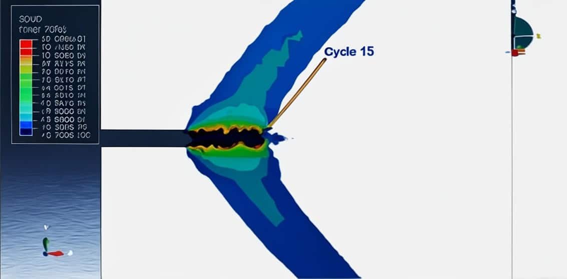
This course provides a comprehensive study of fatigue, fracture mechanics, and crack propagation, with emphasis on computational modeling and simulation. Students will learn how cracks initiate, grow, and interact with different loading conditions and materials, from metals to concrete and composite structures.

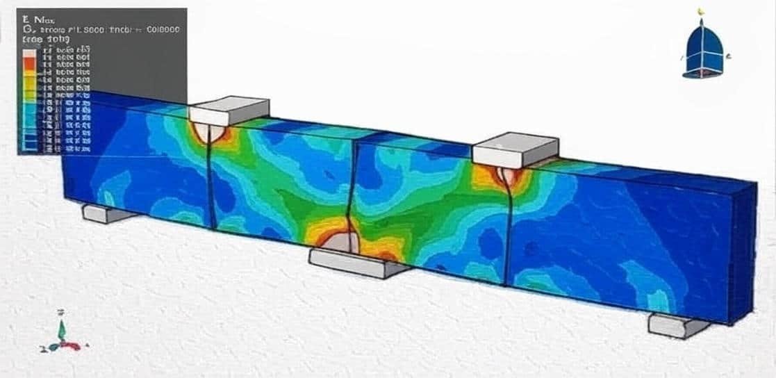
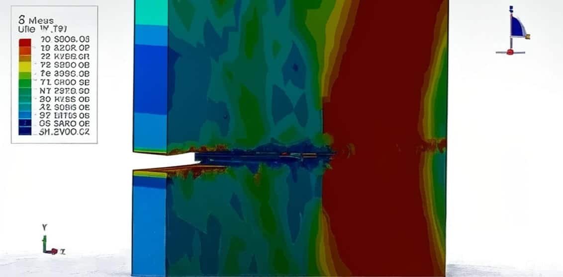
The curriculum progresses from fundamental fatigue and crack growth analyses in steel plates and pressure vessels to advanced XFEM-based simulations for concrete, wood, and reinforced structures. Key applications include bending tests, crack growth in reinforced concrete beams and walls, and large-scale fracture scenarios such as dam failure under pressure and load.

By combining theory, fracture mechanics principles, and simulation techniques, participants will develop the ability to:

  • Analyze fatigue life and crack growth in metals and reinforced materials.

  • Apply extended finite element methods (XFEM) to model crack propagation.

  • Evaluate structural safety under axial, bending, and pressure loads.

  • Simulate large-scale fracture processes in engineering structures.

This course equips learners with the analytical and practical skills needed to model, predict, and assess structural integrity across a wide range of engineering applications.

Course Content

Example 1: Fatigue phenomenon analysis of a 2D steel plate
In this lesson, the fatigue phenomenon analysis of a 2D steel plate is studied. A two-dimensional part for the steel and wire part to define the initial crack length has been used. An elastic material coupled with a traction separation law to consider the fracture and crack growth in the plate has been implied. It is well known that after several repetitive loading cycles, the response of an elastic-plastic structure, such as an automobile exhaust manifold subjected to large temperature fluctuations and clamping loads, may lead to a stabilized state in which the stress-strain relationship in each successive cycle is the same as in the previous one. The classical approach to obtain the response of such a structure is to apply the periodic loading repetitively to the structure until a stabilized state is obtained. This approach can be quite expensive, since it may require the application of many loading cycles before the stabilized response is obtained. To avoid the considerable numerical expense associated with a transient analysis, a direct cyclic analysis can be used to calculate the cyclic response of the structure directly.

  • Abaqus files
  • Video
    23:38

Example 2: Modeling of the 3D fatigue phenomenon
In this section, the modeling of the 3D fatigue phenomenon by using the Paris law is investigated. Metal fatigue is the process by which a material is slowly damaged by stresses and strains that are less than those needed to actually break the material apart. For example, a steel wire might be used to suspend weights that are less than the amount needed to cause the wire to break apart (its tensile strength). Over time, however, those weights might slowly cause defects to develop in the steel. These defects might occur as scratches, notches, particle formation, or other abnormalities. At some point, these defects may become so great that the steel wire actually breaks apart even though its tensile strength had never been exceeded. The process of metal fatigue varies considerably from one material to another. In some cases, defects show up almost as soon as stresses and strains are applied to the material and grow very slowly until total failure occurs. In other cases, there is no apparent damage in the material until failure almost occurs. Then, in the very last stages, defects appear and develop very rapidly prior to complete failure. The amount of stress or strain needed to bring about metal fatigue in a material—the fatigue limit or fatigue strength of the material—depends on several factors. First is the material itself. In general, the fatigue limit of many materials tends to be about one-quarter to three-quarters of the tensile strength of the material itself. Another factor is the magnitude of the stress or strain exerted on the material. The greater the stress or strain, the sooner metal fatigue is likely to occur. Ultimately, environmental factors contribute to metal fatigue. A piece of metal submerged in a saltwater solution, for example, is expected to exhibit metal fatigue sooner than the same piece of metal tested in air. Similarly, materials that have undergone some oxidation tend to experience metal fatigue sooner than unoxidized materials.

Example 3: Analysis of the Half-Elliptical Crack in a Pressurized Vessel
In this case, the analysis of the Half-Elliptical Crack in a Pressurized Vessel is done through a comprehensive tutorial. In this case, to model the load changing with elevation, the DLOAD subroutine is selected. The analysis of half-elliptical cracks in pressurized vessels involves determining stress intensity factors (SIFs) and fracture parameters to predict crack growth and prevent catastrophic failure. This is achieved through methods like Finite Element Analysis (FEA) or boundary element methods, which model the crack's geometry, material properties, and applied pressure to calculate stresses. Key factors influencing crack behavior include crack depth, aspect ratio, material properties, and the level of stress constraint, which affects the location of fracture initiation and the overall safety assessment of the vessel.

Example 4: XFEM Crack Growth Modeling in a Pressure Vessel

Example 5: 2D XFEM Crack Growth Simulation in Concrete
In this lesson, the 2D XFEM Crack Growth Simulation in Concrete is studied. To model crack growth, the fracture law as a material property is considered. Growth simulation in concrete encompasses two main phenomena: the early-age hydration of C-S-H (Calcium Silicate Hydrate) gel and the crack growth that occurs due to damage accumulation. Hydration simulation focuses on the microscopic processes of C-S-H development and its impact on concrete porosity and shrinkage, while crack growth simulation uses advanced numerical methods like the Extended Finite Element Method (XFEM) to analyze fracture propagation in concrete structures under various loads.

Example 6: Crack and fracture analysis on the four-point bending test
In this case, the crack and fracture analysis on the four-point bending test is done. The piece has a cracked edge with a three mm length under the bending load. In this example two-dimensional part has been used, and the pieces are modeled with steel material, and the contour integration procedure is suitable for this analysis.

Example 7: Crack propagation in a reinforced concrete beam under bending Load
In this lesson, the crack propagation in a reinforced concrete beam under bending Load is studied. The concrete part is modeled as a three-dimensional part with traction separation behavior, which is defined in the material property. To model crack growth under static load XFEM procedure with a planar crack has been selected. During the analysis crack began to initiate, and after that, concrete fractures occurred.

Example 8: Crack growth in the Koyna dam under earthquake load
In this section, the crack growth in the Koyna dam under earthquake load is investigated. This example is considered an analysis of the Koyna dam, which was subjected to an earthquake of magnitude 6.5 on the Richter scale on December 11, 1967. The example illustrates a typical application of the concrete damage based on traction separation laws. The dam is modeled as a two-dimensional part with damaged material. Before the dynamic simulation of the earthquake, the dam is subjected to gravity loading and hydrostatic pressure. In the Abaqus/Standard analysis, these loads are specified in two consecutive static steps, using a distributed load with the load type labels GRAV (for the gravity load) in the first step and HP (for the hydrostatic pressure) in the second step. To model physical crack growth XFEM procedure has been selected.

Example 9: XFEM crack growth in concrete containing wood as aggregates
In this case, the XFEM crack growth in concrete containing wood as aggregates is done. The critical mechanical characteristics governing the usability of concrete containing wood shavings as aggregates are mechanical strength and durability. There is a renewed interest in the use of wood-based composite materials because of their ability to regulate indoor climate. Numerous studies have shown that the hygroscopic behavior of materials of vegetable origin makes it possible to regulate ambient humidity. The shavings were waste from the wood industry, and they came from spruce species wood, which belongs to the category of softwood. This timber is widely used in construction thanks to its rapid growth and low price. The extended finite element method was used in this simulation. It is based on the concept of partition of unity, which allows the presence of discontinuities in a finite element by enriching degrees of freedom using special displacement functions.

Example 10: Crack growth modeling of the concrete wall under normal and transverse load
In this lesson, the crack growth modeling of the concrete wall under normal and transverse load is studied. The concrete wall is modeled as a three-dimensional part, and the crack plane as a shell part. For the concrete traction separation law, the maximum principal stress, with fracture energy, has been used. It is an important point to use that material model to observe the crack propagation physically. The general static step is appropriate for this type of analysis. The XFEM crack growth procedure is used to model crack propagation inside the concrete wall by defining the crack plane as the initial crack location.

Example 11: Analysis of the crack growth in the RC beam under five-point bending
In this lesson, the analysis of the crack growth in the RC beam under five-point bending is studied. The concrete beam is modeled as a three-dimensional solid part. The bars and strips are modeled as three-dimensional wire parts. The rigid bodies as supporters and hydraulic jacks, are modeled as three-dimensional rigid shell parts. Traction-separation law is used to model concrete behavior and crack growth. The response of cohesive behavior in the enriched elements in the model is specified. The maximum principal stress failure criterion is selected for damage initiation, and an energy-based damage evolution law based on a power-law fracture criterion is selected for damage propagation. The steel material with elastic-plastic data is used for the bars and strips. The general static step with some changes in the convergence algorithm is applied. The steel members are embedded inside the concrete host, and the surface-to-surface contact with friction as a contact property is used among all rigid bodies and the concrete beam. The XFEM procedure to study crack growth is used to monitor crack propagation in the RC beam.

Example-12: Analysis of low cyclic fatigue damage based on hysteresis energy
In this section, the analysis of low cyclic fatigue damage based on hysteresis energy in Abaqus software is investigated. It is well known that after several repetitive loading cycles, the response of an elastic-plastic structure, such as an automobile exhaust manifold subjected to large temperature fluctuations and clamping loads, may lead to a stabilized state in which the stress-strain relationship in each successive cycle is the same as in the previous one. The classical approach to obtain the response of such a structure is to apply the periodic loading repetitively to the structure until a stabilized state is obtained. This approach can be quite expensive, since it may require the application of many loading cycles before the stabilized response is obtained. To avoid the considerable numerical expense associated with a transient analysis, a direct cyclic analysis can be used to calculate the cyclic response of the structure directly. In the direct cyclic analysis, the Fourier representation of the solution and the residual vector are used to obtain the stabilized cyclic response directly. The damage initiation criterion is a phenomenological model used to predict the onset of damage due to stress reversals and the accumulation of inelastic strain in low-cycle fatigue analysis. Once the damage initiation criterion is satisfied at a material point, the damage state is calculated and updated based on the accumulated inelastic hysteresis energy density per cycle, Δw, for a stabilized cycle. The rate of damage in a material point per cycle is given by dD/dN=c3(deltaW/deltaW0)/L Abaqus uses the above damage initiation and evolution based on Hysteresis energy in the direct cyclic loading. Damage evolution for ductile materials can be defined for any element that can be used with the damage initiation criteria for a low-cycle fatigue analysis in Abaqus/Standard

Example-13: Simulation of the Kalthoff–Winkler experiment crack growth using a peridynamic model
In this case, the simulation of the Kalthoff–Winkler experiment crack growth using a peridynamic model under low velocity impact in Abaqus is studied. Both two- and three-dimensional models can be used to model the plate. Fracture and failure analysis has always been one of the major concerns in theoretical studies and engineering applications. For mode II dynamic loading conditions with high rates, experiments have demonstrated that failure in shear form can be easily obtained if suitable fixtures are applied. The technique of loading edge cracks by edge impact (LECEI) introduced by Kalthoff provides such a fixture, in which a loosely positioned flat plate (target) with two parallel notches is impacted by a projectile. During the impact process, a compressive stress wave is triggered, and the displacement associated with this stress wave creates a pure shear mode II loading condition in a very short period, and an effective mode II crack propagation path can then be observed. The Kalthoff-Winkler experiment is a benchmark dynamic fracture problem for predicting crack propagation in an impact-loaded pre-notched plate. In this tutorial, three cases are investigated. The crack angle in all three cases is matched with the experiment.

Reviews

Student Ratings & Reviews

No Review Yet
No Review Yet
179,00 388,00
27 people watching this product now!

Material Includes

  • 1- Tutorial videos
  • 2- Abaqus files
  • 3- Related Documents

Audience

  • 1- Mechanical Engineering
  • 2- Civil Engineering
  • 3- Welding Engineering
  • 4- Material Engineering

Related  Products

See more

Want to receive push notifications for all major on-site activities?