Engineering Downloads

Let’s Learn and Collaborate

Engineering Downloads

Coupled Eulerian Lagrangian and Eulerian analysis Package

269,00 540,00
269,00 540,00
16 people watching this product now!

Material Includes

  • 1- Abaqus files+ Codes
  • 2- Documents
  • 3- Tutorial Videos

Audience

  • 1- Mechanical Engineering
  • 2- Civil Engineering
  • 3- Structural Engineering
  • 4- Aerospace Engineering

What You Will Learn?

  • During this course, you’ll learn all about CEL and Eulerian analysis in Abaqus through 24 tutorials. The course covers a wide range of topics, including FSW, pile–soil interaction, sloshing, subsurface explosions, bird strikes, cold spray, water jetting, spot welding, orthogonal cutting, impacts, collisions, water column collapse, explosive forming, atomic bomb explosions, elevated composite tanks, and many other subjects.

About Course

Coupled Eulerian Lagrangian (CEL) and Eulerian Analysis

In computational mechanics, two common descriptions are used to model how materials move and deform:

  • Lagrangian description: The mesh moves with the material. Each element tracks the same set of particles over time. This is well-suited for solids and structures where deformations are relatively small to moderate. However, when materials undergo very large deformations (e.g., impact, penetration, or fragmentation), Lagrangian meshes can become highly distorted and unstable.
  • Eulerian description: The mesh is fixed in space, and material flows through it. This is ideal for modeling fluids or materials with extreme flow or mixing (e.g., explosions, fluid-structure interaction, soil or sand flow). However, it is less efficient for pure solid mechanics since the mesh does not follow the material.

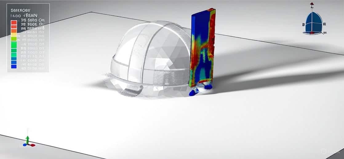
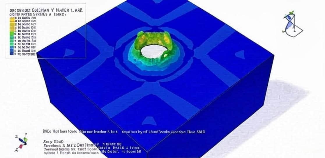
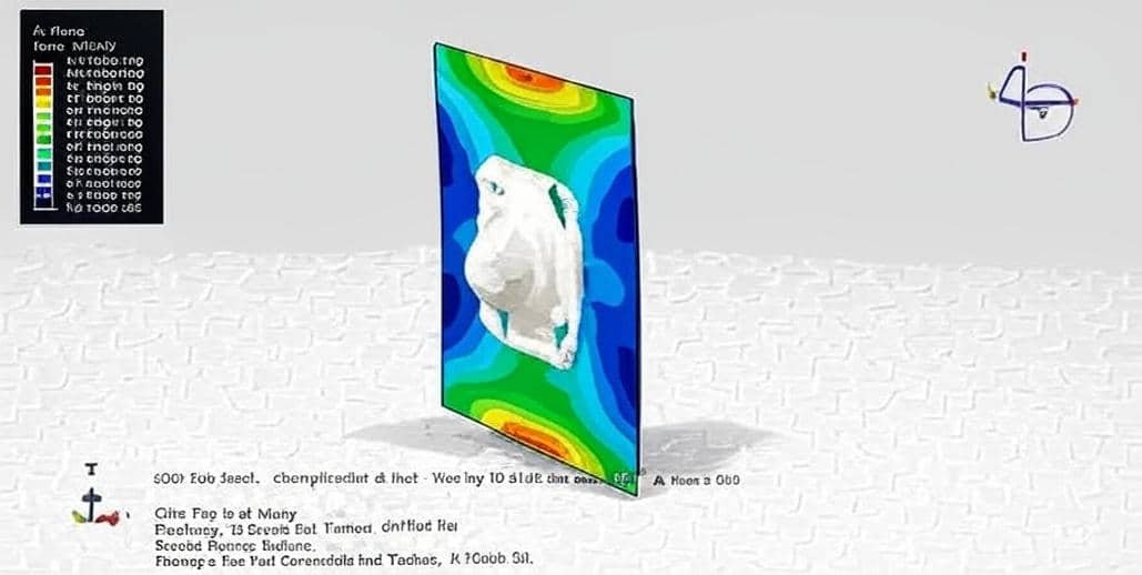
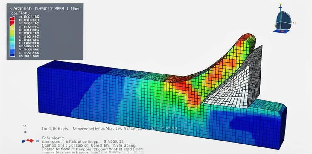
This package includes 24 tutorials that cover all about Euelrian and CEL analysis on Abaqus software. The examples like welding, water sloshing, explosion, impact, forming, spray, soil, water wave, TNT detonation, UNDEX, and many other models.

Coupled Eulerian Lagrangian (CEL) Method

The CEL approach combines the strengths of both frameworks by allowing Eulerian materials (fluid-like or highly deformable materials) to interact with Lagrangian structures (solids) in the same simulation.

  • Eulerian domain: Represents fluids, gases, or deformable materials (e.g., water, soil, explosive gases).
  • Lagrangian domain: Represents solid structures or rigid bodies (e.g., projectiles, barriers, armor).
  • Coupling: Contact algorithms allow interaction between the two domains, enabling accurate modeling of fluid-structure interaction and extreme events.

Applications of CEL Analysis in Abaqus

CEL simulations are widely used in engineering problems where fluids and solids interact dynamically under extreme conditions. Common applications include:

  • Impact and penetration problems (e.g., bullets into armor, spacecraft shielding).
  • Explosion and blast simulations (air blast waves impacting structures).
  • Soil and granular flow (penetration of foundations, landslides).
  • Hydrodynamic phenomena (slamming of ships, water entry problems).
  • Manufacturing processes (metal forming, high-speed machining).

Eulerian Analysis Alone

Pure Eulerian simulations (without coupling) are generally used when:

  • Only fluid/gas/material flow is of interest.
  • No major solid structural response needs to be tracked.
  • Examples include fluid mixing, shockwave propagation in air, or detonation modeling.

In summary:

  • Lagrangian = best for solids, small-to-moderate deformation.
  • Eulerian = best for fluids and extreme flow.
  • CEL = best for fluid–structure interaction and problems with both solid and highly deformable/fluid materials.

Course Content

Example-1: Friction Stir Welding of Aluminium Plates using the CEL method
In this lesson, the Friction Stir Welding of Aluminium Plates using the CEL method is studied. The FSW problem is a multi-physics problem that includes excessive material deformation and heat flow. In the current work, a coupled Eulerian Lagrangian (CEL) model is developed using the Abaqus environment to simulate the two phases of the FSW process (plunging and welding). This file contains CAE and an English video file, step by step, of the FSW of two Aluminium plates. During the analysis tool moves and rotates in the plates and creates heat in them. Friction stir welding (FSW) is a solid-state welding process, which is recognized as a better process for joining similar and dissimilar metals and alloys with different physical, chemical, and mechanical properties. Friction stir welding is a complex process that involves the interaction of thermal and mechanical phenomena: excessive material deformation around the pin tool, accompanied by a large heat flow. Finite element modelling (FEM) of the FSW process leads to a better understanding of the effect of the process parameters on the welding process and the weld seam properties. Nowadays, FSW finite element models can be classified into three types: thermal, thermo-mechanical non-flow base, and thermo-mechanical flow-based models. The aluminum workpiece is modeled as a three-dimensional Eulerian part with Johnson-Cook plastic behavior.

  • Abaqus Files
  • Tutorial Video
    00:00

Example-2: Pile penetration into the soil using the CEL method
In this section, the pile penetration into the soil using the CEL method is investigated. Pile foundations are widely used to transfer structural loads into deeper, more stable soil layers. Understanding pile penetration is critical for predicting load-bearing capacity, soil resistance, and displacement behavior. Traditional modeling approaches often face limitations because of the large soil deformations and contact interaction between the pile and soil. Conventional Lagrangian methods struggle because soil elements become highly distorted as the pile penetrates. Eulerian methods alone are not efficient for solids like piles, since they deform very little compared to soil. This is where the Coupled Eulerian–Lagrangian (CEL) method becomes powerful. Soil has been modeled as Eulerian part with Coulomb-Mohr material. Pile has been modeled as a 3-dimensional Lagrangian part of concrete material. An explicit procedure is appropriate for this analysis, and two steps have been defined: in the first step, soil body force was applied, and in the second step pile penetrated the soil.

Example-3: Analysis of the elevated water container under earthquake load
In this case, the analysis of the elevated water container under earthquake load is presented. Elevated water tanks, sometimes called “airy water containers”, are widely used in urban and rural infrastructure for storing and supplying water. They are usually supported by a tower or staging system, which makes them slender and flexible structures. Because of their elevation and the presence of a water mass, these tanks are particularly vulnerable to seismic excitation. Past earthquakes (e.g., Bhuj 2001, Nepal 2015) have shown that elevated tanks often suffer severe damage or collapse, which can disrupt emergency water supply and pose a risk to nearby communities. The container is modeled as a three-dimensional shell with steel material, and for modeling the legs beam element with steel material has been used. Water is modeled as a three-dimensional Eulerian part, and for modeling its behavior Us-Up equation has been implemented. An explicit procedure is appropriate for this type of analysis and earthquake load, as horizontal acceleration is applied

Example-4: Water sloshing analysis in the concrete tank under earthquake load
In this lesson, the water sloshing analysis in the concrete tank under earthquake load is studied. Concrete water tanks are critical infrastructure used for the storage and distribution of water in urban, industrial, and emergency applications. During earthquakes, these tanks are subjected to strong dynamic forces, not only from ground shaking but also from the interaction between the contained water and the tank walls. One of the most important phenomena that governs seismic performance is water sloshing—the oscillatory motion of the free water surface caused by ground excitation. Concrete tank is modeled as a three-dimensional shell with elastic material and water as an Eulerian part with the Us-Up equation. An explicit procedure is appropriate, and 55 seconds has been applied. To define the water initial volume, the volume fraction tool has been implemented. During the analysis, water goes through the vessel, and sloshing occurs under earthquake load

Example-5: Analysis of the buried steel pipelines against Eulerian-Lagrangian subsurface explosion
In this section, the analysis of the buried steel pipelines against Eulerian-Lagrangian subsurface explosion is investigated. Buried pipelines are among the most important elements of lifelines used for the distribution of water, gas, oil, etc. Buried pressurized gas pipelines are likely to be endangered by accidental explosions in process industries, explosives factories, open pit mines, quarries, public works, or even intentional explosions near a pipeline. Multiple explosions on the route of oil and gas transmission pipelines during recent years demonstrate that terrorist attacks and sabotage have unfortunately increased. In this tutorial CEL explosion has been modeled. For this purpose, a fully coupled 3D finite element model was developed using a combined Eulerian-Lagrangian method. The simplified Johnson-Cook material model, the JWL equation of state, and the ideal gas equation of state were employed for modeling the pipe material behavior, charge detonation, and air, respectively. In addition, soil mass behavior was modeled applying a Coulomb-Mohr plasticity.

Example-6: Bird strike modeling using a hybrid Eulerian–Lagrangian formulation
In this case, the bird strike modeling using a hybrid Eulerian–Lagrangian formulation is done. The work presented in this paper deals with the application of explicit finite element analyses in order to predict bird strike-induced impact damage on A very common example of foreign object impact in air transport is a bird strike. Due to the increased density of air transport and changing migration routes of flocking birds Aluminium wall. This impact loading still presents a significant threat to the safety of airplanes and needs to be accounted for in the certification phase of certain aircraft components. Accurate simulation of the bird strike is still a challenge when applying numerical methods due to the complex physical phenomena that need to be correctly simulated in order to predict the response of the impacted structure. This formulation offers the ability to simulate fluid–structure interaction in which the structure is formulated by a traditional Lagrangian formulation, whereas the fluid is modelled as an Eulerian material. The Eulerian finite element model in CEL analyses is represented by a stationary cube containing multi-material EC3D8R volume elements, which may be completely or partially occupied by material. As the bird strike usually occurs at higher velocities, very high stresses are generated in the bird material.

Example-7: Modeling of the cold spray particle deposition process using the CEL method
In this lesson, the modeling of the cold spray particle deposition process using the CEL method is studied. In recent years, a significant number of studies have been dedicated to the modeling of impact dynamics. For very low-speed impact, such as in the shot peening metal working process, the semi-analytical method can be used for the modeling of both thick (half-space assumption) and thin (finite-depth) structures. In the case of higher-speed impact, such as in the cold spray particle deposition process, three explicit finite element analysis codes, ABAQUS, LS-DYNA, have been used to investigate the whole deformation history of materials. The cold gas dynamic spray process, often called simply “cold spray,” was initially developed in the mid-1980s. In this deposition process, the spray particles (1–۵۰ micro meter) are accelerated to a high velocity (300–1200m/s) by a high-speed gas flow so as to form a dense and high-quality coating thanks to the plastic deformation of the particles impinged upon the solid surface of the substrate. Due to the presence of highly transient nonlinear and dynamic phenomena with contact, the interactions between the particles are. The substrate during cold spray deposition is very difficult to analyze experimentally. Microstructural and microanalytical studies offer little help in identifying the relative contributions of the various bonding mechanisms. Therefore, numerical simulation of the particle/substrate interaction has played a major role in understanding the cold spray bonding mechanism. So we shall start with a brief description of the fundamental concepts of the numerical methods used in this study. The aluminium material for the target and spray is considered as the Johnson-Cook model. Dynamic Temp explicit is appropriate for this type of analysis.

Example-8: Waterjet spot welding analysis using the CEL method
In this model, the waterjet spot welding analysis using the CEL method is presented. Spot welding is one of the most convenient processes to create a quick and permanent joint between lightweight industrial metallic parts and is an integral part of manufacturing processes, especially in the automotive industry. Currently, electrical resistance welding is the most applied method in spot welding. However, it has some limitations. For instance, the welding of metals with far higher melting points and the oxidation of surfaces. Alternative methods such as explosive welding, laser spot welding, and impact spot welding have been introduced to overcome the limitations of conventional methods of spot welding. The latter proposes high quality, steady, and reliable connection between parts by creating solid-phase bonding and interlocking between surfaces. For this purpose, a high velocity projectile or slug of water impacts a predetermined point, and a permanent connection would be created in the neighboring zone. The high pressure produced by the impact of a liquid jet with solid surfaces lasts for very short intervals of time and is followed by a rapid radial flow of the liquid at speeds which may be several times higher than the impact speed itself . Eulerian analysis is a suitable technique for problems in which the material undergoes extreme deformations, especially in the modeling of fluid flow. Through an Eulerian analysis in FEM, the nodes are completely fixed in space, and the material flows through elements that will remain undeformed during the analysis. This advantage would allow the material to experience extreme deformations and strain rates, with the elimination of the possibility of element distortion. On the other hand, in Lagrangian analysis, nodes are fixed within the material, and the material boundary coincides with element boundaries. Therefore, the elements would deform as the material deforms. The Lagrangian technique is well-suited for problems in which the material is in a solid state. Nevertheless, in case of problems in which the strain rate in the solid medium is too high and the material acts like a fluid medium. A dynamic explicit step, surface-to-surface contact with frictional behavior, has been used to define the real behavior between two plates. Uniform material assignment is used to model water as an Eulerian part with an initial velocity.

Example-9: Orthogonal cutting analysis using the CEL method
In this case, the orthogonal cutting analysis using the CEL method is done. Most of the current finite element models of cutting concern the 2D plane strain orthogonal cutting configuration, which, although of valuable interest to study the fundamental phenomena of the process, is still far from most practical cutting operations. The 3D models on the other side usually concern a 2D tool path with a cutting edge that is not straight anymore. The step just after 2D orthogonal cutting is almost not addressed; it is the 3D orthogonal cutting. Due to its high complexity and the large amount of phenomena it involves, the process is mostly studied in orthogonal cutting to mainly reduce the geometrical difficulties and the number of degrees of freedom of the models. The physical coupled phenomena (large strains, strain rates, at high temperatures and temperature gradients, friction, and so on) must still, however, be considered and addressed, which leads to many publications. The well-known, in metal cutting modelling, Johnson-Cook constitutive model is adopted to describe the behavior of the workpiece material, the Ti6Al4V titanium alloy. The Johnson-Cook material model is appropriate for high-strain analysis with rapid speed loading. In the present study, the Johnson-Cook equation with temperature has been considered. Dynamic Temp Explicit is proper for this type of analysis, and the Volume Fraction method has been used to define the initial volume of the workpiece.

Example-10: Numerical modeling of the water impact of a 3D body using the CEL method
In this lesson, the numerical modeling of the water impact of a 3D body using the CEL method is studied. Ocean waves are a significant source of inexhaustible, non-polluting energy. Waves are caused by the wind blowing over the surface of the ocean. In many areas of the world, the wind blows with enough consistency and force to provide continuous waves. A variety of technologies have been proposed to capture the energy from waves, and they differ in their orientation to the waves with which they are interacting and in the manner in which they convert the energy of the waves into other energy forms. Wave energy converters provide a means of transforming wave energy into usable electrical energy. Point absorbers are one type of wave energy converters that have small dimensions relative to the incident wave length. They can capture wave energy from a wave front that is larger than the dimensions of the absorber. The hydrodynamic problem of the water impact of three-dimensional buoys is investigated by the explicit finite element method with a CEL solver. The fluid is solved by using an Eulerian formulation, while the structure is discretized by a Lagrangian approach. In this work, different kinds of three-dimensional structures, including a hemisphere, are considered. Us-Up equations for water and ideal gas formulation for air have been used to define material behavior. During the analysis projectile penetrated the water, and the water splash was obvious.

Example-11: Explosive forming analysis using the CEL method
In this section, the explosive forming analysis using the CEL method is investigated. A food processing equipment using the underwater shock wave has been developed in Japan. The processing mechanism is crushed with the spalling phenomenon of the shock wave. The effect is extraction improving, softening, sterilizing, etc., with non-heating. The pressure vessel for crushing for the processing of a variety of foods has been designed and manufactured. We need a pressure vessel for food processing by underwater shock waves. Therefore, we propose making the pressure vessel by explosive forming. Only a few of these pressure vessels will be made. One design suggestion for the pressure vessel made of stainless steel was considered. The steel plate is modeled as a three-dimensional shell with Johnson-Cook plasticity, TNT as an Eulerian part with the JWL material model, and water with the Us-Up equations. A dynamic explicit procedure is appropriate for this type of analysis. The interaction between the die and plate, holder and plate is considered as surface-to-surface contact. The volume fraction method is used to define the Eulerian material link between the TNT and water.

Example-12: Analysis of the CEL explosion near a metal tube at the depth of water
In this case, the analysis of the CEL explosion near a metal tube at the depth of water is presented. An underwater explosion can be divided into two stages: the shock wave and the bubble pulse. Although both inflict severe damage to the adjacent structure, their damage mechanisms are different. Generally, the pressure caused by the shock wave is very high, but the duration is very short. On the other hand, the pressure caused by the bubble pulse is lower (only 10%–2o% that of the shock wave) but is of a much longer duration, resulting in a force of comparable momentum. Therefore, both the shock wave and the bubble pulse should be considered when examining a near-field underwater explosion. The shock wave causes great damage to a structure whose natural period is of the order of milliseconds and, therefore, usually causes only local damage to a ship. However, the bubble pulse can cause global damage to a ship following an explosion, resulting in a whipping motion if the frequency approaches the eigenfrequency of the ship. In recent years, there has been considerable interest in evaluating the role of the fluid-structure interaction (FSI) in the blast response of a structure. Taylor was among the first to study the momentum transferred to a freestanding plate from a pressure wave with an exponential profile. A dynamic explicit procedure is appropriate for this type of analysis. General contact with the default property has been selected. To define air property ideal gas data, TNT JWL data, water Us-Up parameter, and for aluminum tube, Johnson-Cook plasticity data have been used.

Example-13: Underwater explosion near a concrete dam using the CEL method
In this model, the underwater explosion near a concrete dam using the CEL method is studied. The dam is modeled as a three-dimensional part. The TNT, water, and air are modeled as the Eulerian part. The dam is modeled as a three-dimensional part. The TNT, water, and air are modeled as the Eulerian part. To model air behavior, an ideal gas formulation with viscosity is used. Water is modeled as the Us-Up equation of state, TNT is modeled as the JWL equation to convert chemical energy release from the explosion process to mechanical pressure. To model concrete behavior, Abaqus gives some material models, like CDP and Brittle, which are not suitable to model progressive damage under detonation pulse. The dynamic explicit step with general contact as interaction is used. To model the Eulerian material, there are two ways: Volume fraction and uniform material. In this tutorial, uniform material is used to specify the water, the TNT, and the air amount and location. At the first of the analysis, each material has to fix location, but during the simulation, the volumes of the Eulerian parts mix.

Example-14: Analysis of the CEL explosion near a composite foam-insulated concrete sandwich panel
In this section, the analysis of the CEL explosion near a composite foam-insulated concrete sandwich panel is investigated. Two concrete layers at the front and back are modeled as a three-dimensional solid part. The foam inside those two layers is modeled as a three-dimensional part, and the beam as reinforcement inside the concrete is modeled as a wire part. The TNT is modeled as a sphere, and the Eulerian domain as an Eulerian part. To model the TNT behavior JWL equation of state is used. The Jones-Wilkens-Lee (or JWL) equation of state models the pressure generated by the release of chemical energy in an explosive. This model is implemented in a form referred to as a programmed burn, which means that the reaction and initiation of the explosive are not determined by shock in the material. Instead, the initiation time is determined by a geometric construction using the detonation wave speed and the distance of the material point from the detonation points. To model foam behavior, crashable foam plasticity with hardening is used. The crushable foam model with volumetric hardening uses a yield surface with an elliptical dependence of deviatoric stress on pressure stress. It assumes that the evolution of the yield surface is controlled by the volumetric compacting plastic strain experienced by the material. To model concrete behavior under a massive pressure load, the Johnson-Holmquist model is used, and for a steel beam, Johnson-Cook plasticity and damage are used. The dynamic explicit step is appropriate for this type of analysis. The interaction between concrete slabs and foam is considered as perfect contact, and for all parts in the Eulerian domain, the general contact with property has been selected. The beam parts are embedded inside the concrete's host. The fixed boundary is assigned to the foam and concretes out surfaces.

Example-15: Modeling of the CEL explosion near a steel column and concrete foundation in interaction with soil
In this case, the modeling of the CEL explosion near a steel column and concrete foundation in interaction with soil is presented. The steel column and steel plate are modeled as a three-dimensional solid part. The TNT and soil are modeled as a three-dimensional part. The embedded beam inside the concrete is modeled as a wire part. The Eulerian part is modeled as a three-dimensional part. The steel material is used as an elastic-plastic material with ductile and shear-damaged data. The ductile criterion is a phenomenological model for predicting the onset of damage due to nucleation, growth, and coalescence of voids. The shear criterion is a phenomenological model for predicting the onset of damage due to shear band localization. For the TNT, the JWL equation of state is used. The Jones-Wilkens-Lee (or JWL) equation of state models the pressure generated by the release of chemical energy in an explosive. This model is implemented in a form referred to as a programmed burn, which means that the reaction and initiation of the explosive are not determined by shock in the material. Instead, the initiation time is determined by a geometric construction using the detonation wave speed and the distance of the material point from the detonation points. The soil material is modeled as elastic-plastic behavior. The dynamic explicit method is appropriate for this type of analysis. The general contact capability is used to consider all contacts in the domain. The perfect contact between the column and the steel plate, the steel plate and the concrete foundation, is assumed. The proper boundary conditions are assigned to the concrete foundation and Eulerian domain. The volume fraction technique is used to calculate the amount of soil and TNT inside the domain.

Example-16: Investigation of the CEL large-scale bomb explosion(Nuclear detonation)
In this lesson, the investigation of the CEL large-scale bomb explosion(Nuclear detonation) is studied. A nuclear explosion releases vast amounts of energy in the form of blasts, heat, and radiation. An enormous Shockwave reaches speeds of many hundreds of kilometers an hour. The blast kills people close to ground zero and causes lung injuries, ear damage, and internal bleeding further away. In this tutorial, the bomb, air, soil, and concrete building are modeled as three-dimensional solid parts. To model bomb behavior with its huge detonation pressure, the Jones-Wilkins-Lee (or JWL) equation of state models the pressure generated by the release of chemical energy in an explosive. This model is implemented in a form referred to as a programmed burn, which means that the reaction and initiation of the explosive are not determined by shock in the material. Instead, the initiation time is determined by a geometric construction using the detonation wave speed and the distance of the material point from the detonation points. To model, the Ideal gas equation of state is selected. To model soil, the More-Coulomb plasticity is selected. To model a concrete structure with a five-meter thickness, the Johnson-Holmquist model is considered. The dynamic explicit step is appropriate for this type of analysis. The general contact and proper boundary conditions are assigned to all parts. The uniform material format is selected to define the bomb mass and its location near the ground and building.

Example-17: Water column collapsing analysis using Eulerian approach
In this section, the water column collapsing analysis using the Eulerian approach is investigated. The collapse of a water column is a classical fluid dynamics problem that provides insight into free-surface flows, transient hydrodynamic pressures, and impact forces. The setup typically involves a sudden removal of a barrier that initially confines a column of water, allowing it to fall and spread under the influence of gravity. This problem is widely studied in both theoretical and numerical contexts because it represents a simplified model for complex real-world phenomena such as dam-break flows, wave run-up, and liquid sloshing in tanks. Eulerian Framework: Describes fluid motion in a fixed spatial domain, with the governing Navier–Stokes equations solved at discrete grid points. In Eulerian analysis, the free surface is captured using methods such as the Volume of Fluid (VOF), Level Set, or Marker-and-Cell techniques. This example illustrates the pure Eulerian analysis to consider the volume fraction method of water.

Example-18: Eulerian approach to soil impact analysis for crashworthiness application
In this case, the Eulerian approach to soil impact analysis for crashworthiness application is presented. The primary motivation of this study was the development and implementation of an explicit nonlinear dynamic finite element-based methodology for investigating the crashworthiness of small lightweight rigid impacting into soft soil. The crash dynamics of aircraft are highly dependent on the characteristics of the impact terrain, as different terrains produce different structural responses. The technique used to characterise and validate a numerical model for soft soil as an impact terrain is the focus of this paper. The technique used was primarily based on the use of a time-explicit Eulerian-based FE analysis code, and this technique was demonstrated through the FEA of penetrometer drop tests into soft soil. The Eulerian-based FE approach was considered rather than the more commonly used Lagrangian-based FE approach in order to reduce numerical instabilities, which often occur with the use of Lagrangian solvers when considering problems with large deformations, which is a characteristic of crash analyses. These numerical instabilities may prematurely terminate analyses and compromise results. Explicit FE codes have been extensively employed in nonlinear transient dynamic analyses. In this simulation projectile was modeled as a rigid body and the soil as an Eulerian part. During the analysis projectile penetrated into the soil and created a hole in the soil.

Example-19: Analysis of the water mitigation effects on the blast wave using the Eulerian method
In this lesson, the analysis of the water mitigation effects on the blast wave using the Eulerian method is studied. The erection of a water wall around an explosive is an effective method of mitigating the effect of the shock wave and blast pressure of an accidental explosion. Essentially, the high-pressure shock wave produced by detonation aerosolizes the water placed close to the explosive and causes both a phase change of water and the redistribution of internal and kinetic energy over the detonation gases, the blast wave, and barrier material. In view of its effectiveness in attenuating explosions, the water mitigation concept is beginning to attract much attention in both defense and commercial applications for the storage of energetic materials. An explosion is a phenomenon resulting from a sudden release of energy. Usually, after detonation, the solid explosive is transformed into gaseous products, which initially are at extremely high pressure, which may exceed a hundred thousand atmospheres. This pressure is transformed into mechanical work by momentum transfer in the form of pressure waves, which propagate into the surrounding medium. Here, the pressure–volume–energy behavior of the detonation product gases of TNT is modeled with the standard Jones–Wilkins–Lee (JWL) equation of state and a detonation velocity of 6,930 m/s.

Example-20: Modeling of the underwater explosion based on the Eulerian approach
In this section, the modeling of the underwater explosion based on the Eulerian approach is investigated. The main phenomena of underwater explosion include shock wave formation and propagation, bubble pulsation, and migration. Generally, considering the differences of time sequence and time scale, the process of underwater explosion is usually divided into two stages, i.e., the shock wave stage and bubble pulsation stage, and studied individually. At the former stage, the duration of the shock wave is in milliseconds, and the peak pressure can be up to the level of GPa.This stage is usually featured by strong nonlinearity, and the compressibility of the fluid should be considered. TNT behavior is modeled as JWL material, which can convert chemical energy released from the explosion process to mechanical pressure. Water is modeled as the Us-Up equation of state, and air is modeled as an ideal gas. A dynamic explicit step is appropriate for this type of analysis, and proper boundary conditions are assigned to the part. To use the Eulerian procedure, it is necessary to use the volume fraction method or the uniform material method to locate the Eulerian material. In this tutorial uniform material procedure is used. The mesh quality has a huge effect on the wave propagation, so using a small mesh is necessary

Example-21: Bullet penetration models using large deformation explicit finite element simulations of rapid penetration in soil
In this case, the bullet penetration models using large deformation explicit finite element simulations of rapid penetration in soil are done through a comprehensive tutorial. The bullet is modeled as a three-dimensional part, and the soil as an Eulerian model. Bullet penetration in soil depends on several factors, including bullet type, velocity, soil composition, and moisture content. Soil acts as an effective bullet stopper over sufficient depth, but penetration varies widely based on bullet energy and soil properties. Wet, compacted soils generally resist deeper penetration compared to dry, loose soils.

Example-22: Analysis of the shock pressure and shock-wave attenuation near a blast hole in rock
In this lesson, the analysis of the shock pressure and shock-wave attenuation near a blast hole in rock is studied. The CEL approach is selected to model the blast load in the borehole. The Johnson-Holmquist material model is selected to demonstrate the rock brittle damage under the explosion. The JWL equation of state is considered to model the TNT or explosive charge behavior. When an explosive detonates in a blast hole, it generates an extremely high-pressure shock wave propagating radially into the surrounding rock. Understanding shock pressure and attenuation helps optimize blast design for efficient rock fragmentation while minimizing damage to surrounding structures.

Example-23: Seismic and Sloshing analysis of the elevated CFRP composite tank
In this section, the seismic and sloshing analysis of the elevated CFRP composite tank is investigated. Airy Carbon Fiber Reinforced Polymer (CFRP) composite tanks are widely used in aerospace, automotive, and energy storage applications due to their high strength-to-weight ratio, corrosion resistance, and durability. However, when these tanks contain liquids (such as fuel or cryogenic fluids), they are subjected to dynamic loads from seismic activity and fluid sloshing, which can affect structural integrity. Seismic and sloshing analysis of an airy CFRP composite tank requires a multidisciplinary approach combining structural dynamics, fluid mechanics, and material science. Advanced simulation techniques (CEL, SPH, Acoustic CFD), along with experimental validation, are essential for ensuring safety and performance in critical applications

Example-24: Analysis of the subsurface UHPC tunnel with GFRP protection against internal blast using the CEL method
In this case, the analysis of the subsurface UHPC tunnel with GFRP protection against internal blast using the CEL method is presented. The increasing threat of blast loads on critical underground infrastructure has necessitated advanced protective measures for tunnels. Ultra-High Performance Concrete (UHPC) has emerged as an excellent material for blast-resistant structures due to its superior strength and energy absorption capacity. When combined with Glass Fiber-Reinforced Polymer (GFRP) protection, UHPC tunnels can exhibit enhanced resistance to internal explosions. Numerical simulations using the Coupled Eulerian-Lagrangian (CEL) method in Finite Element (FE) analysis provide an efficient way to model the complex interactions between blast waves, tunnel structures, and protective linings. The CEL approach is particularly suitable for blast simulations as it avoids excessive mesh distortion by treating the explosive and air as Eulerian materials while modeling the tunnel structure as a Lagrangian domain. This study investigates the non-linear dynamic response of a subsurface UHPC tunnel reinforced with GFRP protection under internal blast loading using the CEL method. Key aspects include. This study contributes to the design of blast-resistant underground structures, offering insights into the performance of advanced composite materials under extreme loading conditions. The CEL-based FE approach provides a robust framework for future safety assessments of critical infrastructure

Reviews

No Review Yet
No Review Yet
269,00 540,00
16 people watching this product now!

Material Includes

  • 1- Abaqus files+ Codes
  • 2- Documents
  • 3- Tutorial Videos

Audience

  • 1- Mechanical Engineering
  • 2- Civil Engineering
  • 3- Structural Engineering
  • 4- Aerospace Engineering

Related  Products

See more

Want to receive push notifications for all major on-site activities?