Engineering Downloads

Let’s Learn and Collaborate

Engineering Downloads

Concrete Slabs Analysis Package in Abaqus

249,00 489,00
249,00 489,00
11 people watching this product now!

Material Includes

  • 1- Abaqus Files+ Codes
  • 2- Documents
  • 3- Tutorial Video

Audience

  • 1- Civil Engineering
  • 2- Structural Engineering
  • 3- Mechanical Engineering

What You Will Learn?

  • During this course, you'll learn all about concrete and composite slabs through 20 advanced tutorials. Topics include three- and four-point bending, RC slabs with PET foam cores, bolted shear connectors, shear–bending failure modeling, CONWEP air blasts, CEL explosions, fire behavior, low-energy impacts, voided RC slabs, steel–concrete composite slabs, aluminum–concrete beams, and more.
  • You'll also explore advanced material models such as Concrete Damaged Plasticity, Johnson–Holmquist, Ductile Damage, and Johnson–Cook hardening and damage. The course covers materials like normal concrete, high-strength concrete, UHPC, UHPFRC, CFRP, BFRP, GFRP, steel, aluminum, TNT, and others.

About Course

Introduction to Concrete Slabs Analysis and Simulation

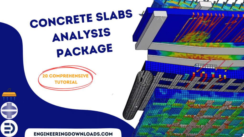
Concrete slabs are fundamental structural elements used in buildings, bridges, pavements, and industrial floors. They are designed to resist loads through a combination of bending, shear, and axial forces while ensuring adequate stiffness and serviceability. Because slabs are often subjected to complex loading and boundary conditions, analytical solutions can be difficult to obtain. As a result, numerical simulation has become an essential tool in the design and performance evaluation of concrete slabs.

This package includes 20 tutorials that cover all about concrete slabs, such as bending, four-point bending, bolted shear connectors in composite slab, concrete ribbed slab,  blast loading,  fire analysis, sequential CEL explosion, low-energy impact,  interior voided RC slab,  air blast, SPH explosion, UHPC slab, profiled steel deck composite slab, low-velocity impact, steel-concrete slab, and …

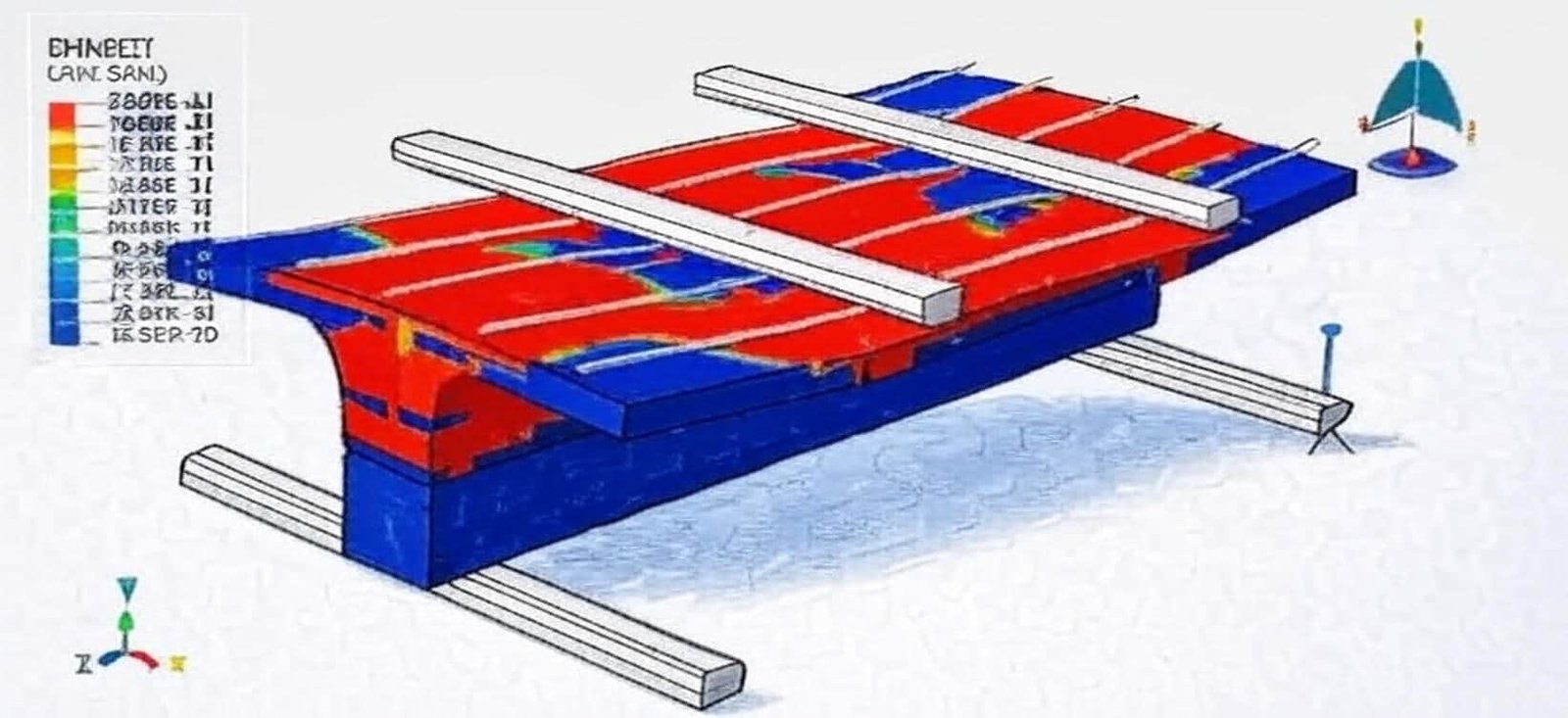
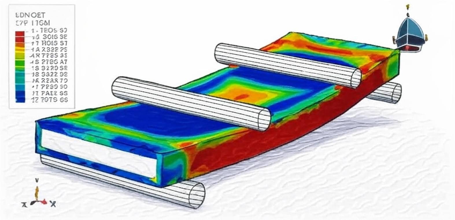
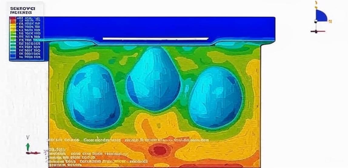
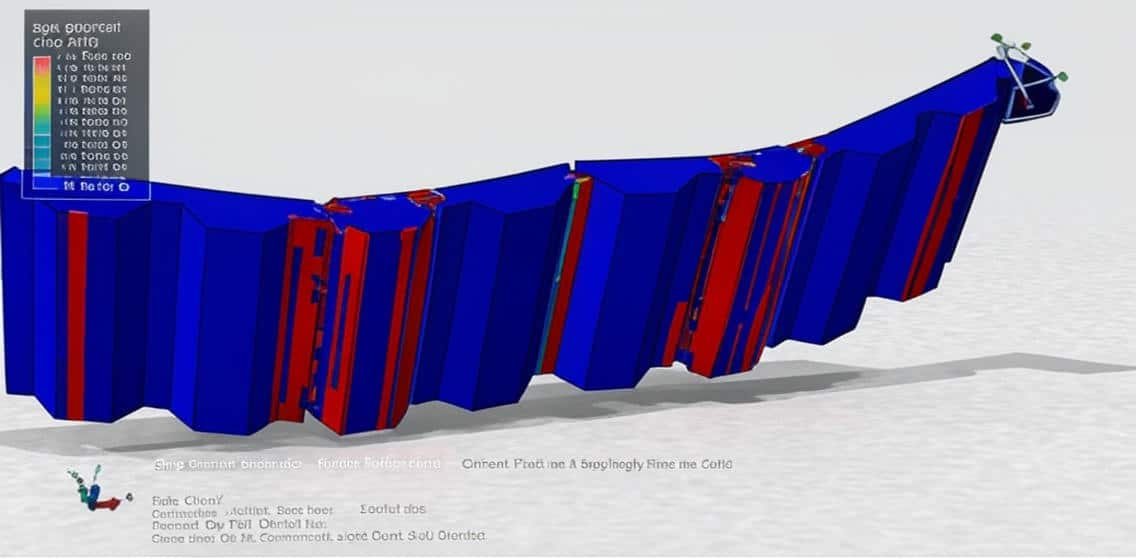
Finite Element Analysis (FEA), implemented in software such as Abaqus, enables engineers to model the nonlinear behavior of concrete, including cracking, crushing, creep, and reinforcement interaction. These simulations provide insights into stress distribution, deflection patterns, and failure mechanisms that are difficult to observe experimentally. Using the Concrete Slab Package in Abaqus, users can simulate various slab configurations—such as one-way or two-way slabs, flat plates, and ribbed slabs—under static, dynamic, or thermal loads.

Key objectives of concrete slab analysis and simulation include:

  • Evaluating load-bearing capacity and deflection performance.

  • Studying crack propagation and reinforcement effects.

  • Optimizing material usage and slab thickness for economy and sustainability.

  • Validating designs against relevant codes and standards (e.g., ACI, Eurocode).

Concrete slab analysis and simulation represent a crucial part of structural engineering research and design. By using advanced software like Abaqus, engineers can accurately model complex slab behaviors, reduce experimental costs, and improve design reliability. The integration of FEA results into design processes allows for the creation of more efficient, safe, and sustainable structures, aligning with modern engineering standards and sustainability goals.

Course Content

Example-1: Analysis of an RC slab with PET foam core under four-point bending
In this lesson, the analysis of an RC slab with PET foam core under four-point bending is studied. The concrete and PET foam are modeled as three-dimensional solid parts. The steel reinforcements are modeled as wire parts. The appropriate choice of material model, being suitable for the description of stress-strain relation in a foam, is important. However, various foams have extremely different properties; thus, the task is not so simple, and each type of foam needs to be carefully analyzed. Usually, experimental identification of the material properties of the foam is done. Procedures exist, according to for example ISO or ASTM standards, that enable the determination of elastic and strength properties of the core, which are valid for PET foams as well. What is more, technical data sheets are provided for foams that are available on the market, which include information on the most important material properties declared by producers and identified according to the aforementioned standards. In such a case, it seems that the description of material behavior should be easier. Nevertheless, the standards give recommendations that can be helpful only when the elastic response of the core is considered. Furthermore, the fact that the foam can be generally anisotropic is not mentioned. For these reasons, some difficulties can be encountered when detailed analyses of sandwich response are conducted, and the identification of foam core material properties according to standards seems to be insufficient in such situations. Both dynamic and static are selected to demonstrate the bending load.

  • Abaqus Files
  • Document
  • Tutorial Video
    27:57

Example-2: Modeling of the bolted shear connectors in composite slabs with steel deck
In this section, the modeling of the bolted shear connectors in composite slabs with steel deck is investigated. The steel beam, concrete, and bolts are modeled as a three-dimensional solid part. The steel deck is modeled as a shell part. Over the past few years, more concerns related to the building environments have been greatly addressed to enhance the current building environment and empower future generations to benefit from an ideal life and adequate resources to meet their needs. These concerns include sustainability, energy conservation, construction materials, building deconstruction systems, and recycling/reusing building materials. As far as we know, construction significantly affects the living environment, in particular, the management and demolition of building structures after their intended design service life. The steel-concrete composite structures are widely used nowadays. in bridges and high-rise buildings. For achieving the composite action between the composite concrete slabs and steel beams, the welded shear connectors are used in many composite systems due to their shear loading resistance. Consequently, such welded shear connectors make it almost impossible to dismantle, alternate, and deconstruct the composite structures after their design service life To model steel behavior under large deformation, Johnson-Cook hardening and damage are selected. The concrete damaged plasticity is a good material model for concrete. A dynamic explicit step with the mass scale technique is selected for this analysis.

Example-3: Shear-bending failure modeling of cracked concrete ribbed slabs strengthened with UHPFRC
In this case, the shear-bending failure modeling of cracked concrete ribbed slabs strengthened with UHPFRC is presented. The slab has three sections: untracked concrete, cracked concrete, and UHPFRC. All three parts are modeled as three-dimensional solid parts. The steel reinforcements are modeled as wire parts. The preservation of historical buildings, or landmark structures, usually requires interventions to comply with the character of the building, but additionally to satisfy the demands of future use. Structural safety demands might call for strengthening measures, or, in some cases, even partial replacement. However, further to structural requirements, rehabilitation may also be necessary for cases of a switch in the building use, expectations of increased loadings, or expansions. After thoroughly evaluating candidate solutions, it was decided to employ Ultra High Performance Fiber Reinforced Composite material (UHPFRC) atop the slabs to increase the strength capacity of the sections. The use of UHPFRC for structural rehabilitation has been increasingly expanding in the past decades. To model cracked concrete, untracked concrete, and UHPFRC, the Concrete Damaged Plasticity is selected. Both dynamic and static steps are used to model the flexural behavior of the slab.

Example-4: Analysis of a new type of reinforced concrete composite slab with a joint
In this lesson, the analysis of a new type of reinforced concrete composite slab with a joint is studied. The precast plank concrete and in-situ concrete topping are modeled as three-dimensional solid parts. The steel reinforcements are modeled as wire parts. Precast concrete (PC) structures can be seen in buildings throughout the world due to their advantages of better construction quality, lower labor costs, and shorter construction times. Composite slab, as one of the most commonly used elements in floor systems of PC residential buildings, is formed by bottom precast planks and a cast-in-situ concrete topping. To improve the flexural stiffness of the bottom precast plank and increase the bonding performance between the precast plank and the cast-in-situ concrete topping, lattice girders are usually installed in the precast plank. However, due to the limitation of the thickness of the composite slab with lattice girders used in China, the height of the lattice girder is usually small. As a result, the improvement in stiffness of the precast plank by the lattice girder is limited, which requires the erection of vertical supports during the construction process, increasing the construction cost and prolonging the construction period. Composite slabs, consisting of a precast plank and a cast-in-situ concrete topping, are the most commonly used horizontal structural components in prefabricated buildings. To solve the problem that the precast plank of the composite slab is easy to crack and a lot of vertical supports are needed in its construction, this study proposes a new type of composite slab with a joint. The precast plank of this novel composite slab is fully prefabricated in the midspan area, and concrete is poured on-site only at the surrounding joints.

Example-5: Dynamic response of a concrete slab sandwich plate under close-range blast loading based on the CEL method
In this section, the dynamic response of a concrete slab sandwich plate under close-range blast loading based on the CEL method is investigated. The concrete slab, TNT, and Eulerian domain are modeled as three-dimensional parts. The steel beams are modeled as shell parts. The steel bars are modeled as wire parts. In recent years, there has been a rise in bombing terrorist bombings and accidental explosions worldwide. Recently, a new type of building Concrete slab-steel beam, has been proposed. The Coupled Eulerian-Lagrangian (CEL) method is a numerical approach that combines the Eulerian and Lagrangian finite element methods to address fluid-structure problems. By leveraging the strengths of both methods, the CEL method effectively models the motion and interaction of objects within a flow field. It excels in handling complex solid surfaces, fluid-structure interfaces, and multi-physics field coupling problems, accurately describing object shapes, boundary conditions, large deformations, and displacements. Moreover, the CEL method is proficient in simulating material deformation processes and can effectively tackle coupled fluid flow and solid mechanics problems, capturing diverse fluid behaviors like turbulence and vortices. Employing high-precision numerical algorithms, the CEL method ensures the stability and accuracy of numerical solutions in solving fluid and solid mechanics equations. To model steel parts' behavior, the Johnson-Cook hardening and damage model is used. The Johnson-Holmquist brittle model is considered to define concrete behavior under severe load. The JWL equation of state is used to define the TNT explosive material. Dynamic explicit steps with general contact capability and some to perform this simulation are considered.

Example-6: Modeling of the hollow-core slabs under fire conditions and four-point bending
In this case, the modeling of the hollow-core slabs under fire conditions and four-point bending is presented. Precast/prestressed concrete hollow core (PCHC) slabs with a reduction in self-weight due to longitudinal voids, and without shear reinforcement due to the extrusion method, are most susceptible to shear failure. When subjected to shears, hollow-core slabs commonly failed in a critically brittle manner with the formation of web-shear cracks. In the event of a fire, the shear behavior of PCHC slabs is governed by the temperature-reduced material properties of concrete and strands, and thermal stresses due to a temperature gradient over the depth of the hollow-core sections. All heat transfer methods, such as Conduction, Convection, and Radiation, are used. Conduction heat transfer is the transfer of heat through matter (i.e., solids, liquids, or gases) without bulk motion of the matter. In another ward, conduction is the transfer of energy from the more energetic to the less energetic particles of a substance due to interaction between the particles. Convection. Convective heat transfer is heat transfer between two bodies by moving gas or fluid currents. In free convection, air or water moves away from the heated body as the warm air or water rises and is replaced by a cooler parcel of air or water. Radiation heat transfer is the energy that is emitted by matter in the form of photons or electromagnetic waves. Radiation can be important even in situations in which there is an intervening medium. An example is the heat transfer that takes place between a living entity with its surroundings. Both sequential and direct methods can be used to model fire analysis and the bending test. In this model, the direct method is selected. All proper boundaries and contacts are assigned to all parties

Example-7: Fire analysis of a composite beam(RC concrete slab-steel beam)under bending load
In this lesson, the fire analysis of a composite beam(RC concrete slab-steel beam)under bending load is studied. The concrete slab is modeled as a three-dimensional solid part. The steel reinforcements are modeled as wire parts. The steel beam is modeled as a three-dimensional solid part, and a rigid body to apply a load is also used. Steel–concrete composite beams are often employed in office and industrial buildings or bridges and viaducts for fast and economic erection. Most usually, they comprise a steel girder and a reinforced concrete slab interconnected by shear connectors (fasteners). The number of shear connectors largely determines whether the composite cross-section behaves as compact or partially connected. In any case, the deformation of the beam causes some relative tangential displacement (slip) between the steel girder and the concrete slab. While usually being very small, slip can have a substantial effect on the overall ductility of the beam, which indicates that it should be taken into account in the analysis. The issue that plays an important role in the concrete and composite steel–concrete beams' response due to fire is the effect of moisture transport on the temperature and stress distribution histories in the concrete part of the cross-section. In the composite beam context discussed here, we are particularly interested in assessing these effects quantitatively. To model the fire analysis, first fire simulation through a heat transfer model is considered, and the nodal temperatures are extracted from the model as an input for the structural model. In the second stage, the static model is performed bending is applied to the top surface of the concrete slab, and the fire results are implied as the initial situation.

Example-8: Analysis of the sequential CEL explosion in the depth of soil near the RC slab
In this section, the analysis of the sequential CEL explosion in the depth of soil near the RC slab is investigated. The concrete slab is modeled as a three-dimensional solid part, and the steel reinforcement is modeled as a wire part. The Soil and TNT are modeled as three-dimensional solid parts. The surrounding is modeled as a three-dimensional Eulerian part. We first consider an ideal representation of underground explosions. Explosions are a common source of seismic waves and span a range of sizes. Small explosions are used for mining, quarrying, road excavating, and other construction applications, as well as in natural resource exploration and active-source seismic lithospheric study. Large explosions include underground nuclear tests, which produce waves strong enough to be observed on the opposite side of the Earth. Natural explosive or implosive sources are rare, but some may occur as a result of metastable mineralogical phase transitions or magmatic processes. The Concrete Damaged Plasticity is selected for the concrete slab under a massive blast wave. The model is a continuum, plasticity-based, damage model for concrete. It assumes that the two main failure mechanisms are tensile cracking and compressive crushing of the concrete material. The JWL equation of state is used to model the bomb's behaviour underground. The Jones-Wilkins-Lee (or JWL) equation of state models the pressure generated by the release of chemical energy in an explosive. This model is implemented in a form referred to as a programmed burn, which means that the reaction and initiation of the explosive is not determined by shock in the material. Instead, the initiation time is determined by a geometric construction using the detonation wave speed and the distance of the material point from the detonation points. The Mohr-Coulomb plastic model is selected to model soil behavior. The elasto-plastic material model is also used for the steel reinforcements. The dynamic explicit step with general contact capability is selected for this analysis. The TNT parts are placed in the three locations with detonation times for the explosion. Proper boundary conditions are assigned to the RC slab and Eulerian domain. To use the Eulerian materials, the uniform or volume fraction method should be used.

Example-9: Low-energy impact analysis on the concrete slab with pre-tensioned bars reinforced with GFRP
In this case, the low-energy impact analysis on the concrete slab with pretensioned bars reinforced with GFRP is presented. A concrete slab is modeled as a three-dimensional solid part. The GFRP part is modeled as a planar shell part. The steel bars are modeled as three-dimensional wire parts, and the projectile as a discrete rigid part. The model is a continuum, plasticity-based, damage model for concrete. It assumes that the two main failure mechanisms are tensile cracking and compressive crushing of the concrete material. To model concrete behavior under impact load, the CDP model is selected. Damage initiation refers to the onset of degradation at a material point. In Abaqus, the damage initiation criteria for fiber-reinforced composites are based on Hashin’s theory. These criteria consider four different damage initiation mechanisms: fiber tension, fiber compression, matrix tension, and matrix compression. Hashin damage criterion is selected for the GFRP with 8 different layers to consider the damage during the impact. The elastic-plastic property is also used to model the steel bars' behavior. A dynamic explicit step with a mass scale to make acceleration in the simulation has been considered. The general contact algorithm with the contact property is defined for all parts. The steel bars are embedded inside the concrete slab, and a tie constraint is used between the concrete slab and the GFRP plate. The boundary condition is assigned to the concrete slab, and the velocity to the projectile. The stress is applied to steel bars to be pre-tensioned. This can be done with temperature or stress.

Example-10: Modeling of the rigid body impact on the interior voided RC slab
In this lesson, the modeling of the rigid body impact on the interior voided RC slab is studied. The RC voided slab is modeled as a three-dimensional solid part. The steel bars are modeled as three-dimensional wire parts. The rigid impactor is modeled as a three-dimensional shell part. In recent modern buildings, voided slabs have been extensively employed because of the high reduction in their self-weight up to 35%. Limited studies have been conducted on such slabs, and no significant drop in the flexural strength was reported due to introducing voids. The Concrete Damaged Plasticity Model (CDPM) was used for defining the two main mechanisms of concrete failure: tensile cracking and compressive crushing. The CDPM was fed stress-strain values in compression and tension, relying on the test compressive strength of concrete. The CDP model is not appropriate for the impact, especially high-velocity impact, and instead, the Johnson-Holmquist model is more suitable. The JH2 model can consider concrete failure and damage during the impact, and it can be used through code or input modifications. The dynamic explicit step is selected for this analysis. The general contact capability with the contact property is used to consider all contacts in the contact domain. The steel reinforcements are embedded inside the concrete slab. The fixed boundary condition is assigned to two sides of the slab, and the initial velocity is assigned to the rigid impactor.

Example-11: Air blast resistance analysis of a composite slab(UHPC-Steel) using cohesive interaction
In this section, the air blast resistance analysis of a composite slab(UHPC-Steel) using cohesive interaction is investigated. The two steel covers are modeled as a three-dimensional solid part. The Ultra-High-Performance concrete is modeled as a three-dimensional solid part. improve the blast resistance of structural panels. The material properties of UHPC, such as super-high tensile and compressive strengths, ductility, and good durability, make UHPC attractive for various engineering structures, especially in bridge engineering. The popularly employed Concrete Damaged Plasticity (CDP) . The model is a continuum, plasticity-based, damage model for concrete. It assumes that the two main failure mechanisms are tensile cracking and compressive crushing of the concrete material. To model the UHPC slab, the CDP model is selected, and it can predict the tensile and compressive damage. To model steel behavior, the elastic and plastic material model is used. The dynamic explicit step is appropriate for this type of analysis. The cohesive interaction by using stiffness, fracture stress, and energy is assigned to the steel- concrete surfaces as a contact property to investigate the separation during the blast. The CONWEP blast technique is used to model TNT and its location.

Example-12: Air blast modeling near a UHPC slab reinforced with BFRP
In this case, the air blast modeling near a UHPC slab reinforced with BFRP is done through a comprehensive tutorial. The Ultra-High-Performance-Concrete is modeled as a three-dimensional solid part. The Basalt fiber reinforced plastic(BFRP) is modeled as a shell part with four layers. and compression data are defined separately, and also tensile and compression damage can be used. Laminated fiber reinforced composite materials are increasingly used in various industries such as aerospace, military, marine, car manufacturing, etc, due to their superior specific strength and stiffness, convenient fabrication of complicated products and structures, corrosion and environmental resistance, as well as their competitive cost for fabrication. The elastic model lamina type and Hashin’s damage criterion are used to model BFRP behavior under the blast load. The dynamic explicit step is appropriate for this type of analysis. The ideal contact is selected between the UHPC surface and the BFRP composite parts. The COWEP blast explosion procedure is considered. In this way, the amount of the TNT and its locations should be defined.

Example-13: SPH explosion modeling near an RC slab using the CDP model coupled with strain rate
In this lesson, the SPH explosion modeling near an RC slab using the CDP model coupled with strain rate is studied. The RC slab is modeled as a three-dimensional solid part. The steel bars are modeled as three-dimensional wire parts. The TNT is modeled as a three-dimensional solid sphere. (CDP) model. Arguably, the CDP model is one of the most popular concrete damage-plasticity models in the literature and engineering practices. It is one of the most promising concrete constitutive models used for the simulation of concrete damage and failure. The tensile and compression data depend on strain to consider the rapid deformation is considered. To model steel bars, the elastic-plastic material that depends on strain rate is selected. To model TNT, the JWL equation of state has been used. The Jones-Wilkens-Lee (or JWL) equation of state models the pressure generated by the release of chemical energy in an explosive. This model is implemented in a form referred to as a programmed burn, which means that the reaction and initiation of the explosive is not determined by shock in the material. The dynamic explicit step is appropriate for this type of analysis. The embedded region constraint is considered for the steel bars inside the concrete slab. The general contact capability is selected to consider all contacts in the contact domain.

Example-14: Four-point bending analysis of a UHPC slab reinforced with steel bars and GFRP sheet
In this section, the four-point bending analysis of a UHPC slab reinforced with steel bars and GFRP sheet is investigated. The UHP concrete slab is modeled as a three-dimensional solid part. The steel bars are modeled as three-dimensional wire parts. The GFRP sheet with eight layers is modeled as a three-dimensional shell part. The rigid bodies, as supporters and force bodies, are modeled as a three-dimensional rigid shell. slab behavior under bending load. The steel material with elastic-plastic behavior is selected to model bars. The GFRP sheet is modeled as an elastic material with engineering constant data, and Hashin’s damage criterion is used to investigate the damage propagation during the bending test. A generic static step with some changes to the convergence model is considered to avoid early non-convergence. The surface-to-surface contact with the contact property is used among the rigid bodies with the UHPC slab and the GFRP sheet. The steel bars are embedded inside the concrete host. The perfect contact is assumed between the UHPC slab and the GFRP sheet. The fixed boundary condition is assigned to the two bottom rigid bodies, and the displacement boundary is assigned to the two top rigid bodies with smooth amplitude to apply a smooth load.

Example-15: Simulation of the profiled steel deck composite slab system under four-point bending
In this case, the simulation of the profiled steel deck composite slab system under four-point bending is presented. Composite slabs comprised of cold-formed profiled steel sheet and structural concrete topping are commonly used nowadays for the construction of buildings. In this system, the steel deck serves as a permanent formwork for supporting the concrete and also acts as tensile reinforcement. The strength and performance of the composite slab is also influenced by other factors such as profile geometry, thickness of steel sheeting, concrete types/compressive strength, span, embossments/shear connectors, and steel-concrete interface shear bond controlling the composite action. By adopting suitable profile geometry with or without embossments, sufficient resistance against steel-concrete vertical separation and horizontal slippage can be achieved. The interfacial shear depends on several parameters, including the height, shape, and orientation of the embossment pattern and other shear connectors The concrete is modeled as a three-dimensional part, the steel deck as a shell part, bars as wires, and the connectors between the concrete and deck are modeled as a beam element. under bending. The steel material is defined as elastic elastic-plastic material with ductile damage data. A dynamic explicit step with smooth amplitude to apply the smooth load has been selected. Surface-to-surface contact among rigid bodies and deformable parts has been selected. The bar and connectors are used as embedded parts in the concrete host. The contact between the deck and concrete is assumed as ideal contact.

Example-16: Low-velocity impact behaviour of RC slab strengthening with CFRP strips
In this lesson, the low-velocity impact behaviour of RC slab strengthening with CFRP strips is studied. Reinforced concrete slabs are structural members that are commonly used in construction. Slabs are designed by considering the effects of both vertical static and dynamic loads. Impact load is a kind of impulsive dynamic load, which is ignored in the design process of a slab, like other structural members. The behaviour of reinforced concrete slabs under impact loading is an area of research that is still not well understood; however, work in this area continues to be motivated by a broad range of applications. Examples include reinforced concrete structures designed to resist accidental loading scenarios such as falling rock impact; vehicle or ship collisions with buildings, bridges, or offshore facilities; and structures that are used in high-threat or high-hazard applications, such as military fortification structures or nuclear facilities. As a result, considerable work has been undertaken in an effort to develop impact-resistant design procedures and to improve the performance of reinforced concrete structures subjected to impact loads. The concrete slab is modeled as a three-dimensional part with CDP material model, and the CFRP is modeled as a three-dimensional shell part with elastic property coupled with Hashin’s damage, and the bars are modeled as a wire part with elastic-plastic material model.

Example-17: Bending test analysis of an aluminum-concrete beam
In this case, the bending test analysis of an aluminum-concrete beam is presented. Contemporary designers should look for new solutions supporting sustainable construction. Aluminium-concrete composite structures have a lot of applications thanks to the corrosion-resistance and lightness of the aluminum beam. They may be used in composite bridges and in structures that are difficult to access or are located in corrosive or humid environments. Multiple problems inherent in aluminum-concrete structures remain to be solved. Numerical calculations may be a good alternative to laboratory tests, but only if the numerical model is verified. The aluminum beam is modeled as a three-dimensional shell part. The bolt and concrete are modeled as a three-dimensional solid part. The aluminum material is used as an elastic-plastic material for the beam, and the steel material is used as an elastic-plastic material for the bolt. The concrete is modeled as a concrete damaged plasticity material model to observe the tensile and compressive damage during the bending process. Two analyses have been selected for this simulation. In the first analysis, the static stimulation, and in the second analysis, the explicit simulation. The contact between rigid bodies with the beam and the concrete slab is assumed as a surface-to-surface contact with the property of a friction coefficient. The bolts are embedded inside the concrete host.

Example-18: Analysis of the stud-connected steel-UHPC composite girders subjected to four-point bending
In this section, the analysis of the stud-connected steel-UHPC composite girders subjected to four-point bending is done. The performance of steel-concrete composite (SCC) girders for static and dynamic loads depends significantly on the force transfer mechanism at the interface between the steel beam and concrete. Stud-connected SCC girders consist of an effective mechanism to resist the shear force at the interface between the concrete slab and steel beam. Stud connectors significantly increase the shear resistance of the interface and hence assist in increasing the load-carrying capacity of the SCC girder through dowel action. The ultra-high-performance concrete part is modeled as a three-dimensional solid part. The steel beam and stud are modeled as three-dimensional solid parts. To consider the force body and boundary parts, for shell rigid bodies are created. To model concrete material, UHPC material is used. The CDP damaged plasticity is considered for to use of compression and tension stress separately. The data for the UHPC are extracted from the reference paper. The steel material with elastic-plastic behavior, coupled with a ductile damage criterion to consider damage and failure, is used for the steel beam and studs. The static and dynamic solvers can be used for this type of simulation. The static simulation needs plenty of time, so the dynamic explicit is a better way to overcome this issue. The dynamic explicit step with a smooth step amplitude for the load is similar to a quasi-static simulation. The perfect or ideal contact is considered for the contact between the studs and the UHPC part. The surface-to-surface contact algorithm with contact property is applied to the other contacts in the contact domain.

Example-19: Bending test modeling of a steel-concrete(foamed concrete) composite beam
In this lesson, the bending test modeling of a steel-concrete(foamed concrete) composite beam is studied. The foamed concrete ( containing partial cement replacement) is modeled as a three-dimensional solid part. The steel beam is modeled as a three-dimensional shell part. The steel reinforcement is modeled as a three-dimensional wire par and some rigid parts. Construction materials using concrete are the primary building element of structures worldwide at present. The application of concrete in civil engineering is vast, ranging from the construction of bridges, dams to roads and tall buildings. Ever since the development of concrete, many types of concrete have been manufactured. One of them is foamed concrete. It is a type of lightweight concrete whose dry density ranges from 300 to 1800 kg/m 3, which is up to 87% lighter than the normal weight concrete. The Concrete Damaged Plasticity is used to model the non-linear behavior of the foamed concrete slab. Composite beams with solid or composite slabs have disadvantages in relation to the high operational cost of welding the shear connector on site, the curing time of wet concrete in cold climates, and short spans corresponding to the floor height. The steel material with elastic and plastic behavior with ductile damage criterion is selected. The general static step with some changes in the convergence model is used. The surface-to-surface contact with friction as contact behavior is used to model the interaction between the concrete slab and rigid bodies. The embedded region constraint is selected for the steel reinforcements, which are embedded inside the concrete host. The perfect contact is assumed between the steel beam and the concrete part.

Example-20: Three-point bending analysis of a concrete slab reinforced with FRP
In this section, the three-point bending analysis of a concrete slab reinforced with FRP is investigated. The widespread successful use of composite materials in the automotive, naval, and sporting goods industries has resulted in a technology transfer to civil infrastructure applications. Fiber-reinforced polymers (FRP) are impacting the international concrete industry. FRP combines high-strength glass, carbon, and aramid fibers with polymer resins, and can be used as both internal and external reinforcement for concrete members. FRP provides an alternative to steel reinforcement in areas where seawater, deicing salts, and corrosives can destroy the structural integrity of a concrete member due to deterioration of the steel reinforcement. The design philosophy for FRP-reinforced concrete is based on principles of equilibrium, compatibility of strains, and the stress-strain characteristics of the materials involved. The brittle behavior of both FRP reinforcement and concrete must be considered. Crushing of the concrete or FRP rupture is the mechanisms that control the failure of the section. For concrete crushing, the Whitney rectangular stress block is used to approximate the concrete stress distribution at ultimate strength conditions. For FRP reinforcement, the linear-to-failure stress-strain relationship must be used. The concrete slab is modeled as a three-dimensional part with CDP material to observe damage propagation under bending load, and epoxy-glass fiber as reinforcement is modeled as a three-dimensional shell part with elastic material coupled with a failure stress to check the fiber damage on the visualization.

Reviews

No Review Yet
No Review Yet
249,00 489,00
11 people watching this product now!

Material Includes

  • 1- Abaqus Files+ Codes
  • 2- Documents
  • 3- Tutorial Video

Audience

  • 1- Civil Engineering
  • 2- Structural Engineering
  • 3- Mechanical Engineering

Related  Products

See more

Want to receive push notifications for all major on-site activities?