Engineering Downloads

Let’s Learn and Collaborate

Engineering Downloads

Composite Analysis and Simulation Package

279,00 598,00
279,00 598,00
22 people watching this product now!

Material Includes

  • 1- Abaqus Files
  • 2- Paper and Document
  • 3- Tutorial Videos

Audience

  • 1- Mechanical Engineering
  • 2- Composite Material Engineering
  • 3- Aerospace Engineering

What You Will Learn?

  • During this course, you'll learn all about composite materials like CFRP, GFRP, BFRP, AFRP, Green composite, banana-epoxy, jute-epoxy, and bamboo fiber. Besides them, you will have concrete, steel, aluminum, silicon carbide, gelatine, PEEK, foams, masonry wall, UHPC, and many other materials through a bunch of examples like eploxion, air blast, low and high-velocity impact, bending, compression, cyclic loading, and ...
  • This package will make you a master in the composite field.

About Course

Introduction to Composite Material Analysis and Simulation

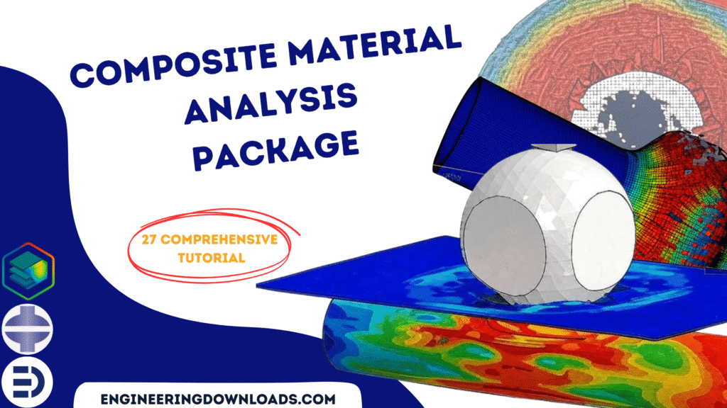
Composite materials are engineered by combining two or more constituent materials with different physical and chemical properties to achieve superior performance compared to their individual components. Typically, composites consist of a matrix material (such as a polymer, metal, or ceramic) reinforced with fibers or particles (such as carbon, glass, or aramid). The result is a lightweight yet strong material with enhanced stiffness, durability, and resistance to fatigue, making composites widely used in aerospace, automotive, marine, wind energy, and civil engineering applications.

This course includes 27 tutorials that cover all about composite materials like CFRP, GFRP, BFRP, AFRP, Banana-epoxy, jute-epoxy, green composite, bamboo fiber, and… in many simulations like high and low-velocity impact, blast, CEL explosion, bending, compression, cyclic loading, and …

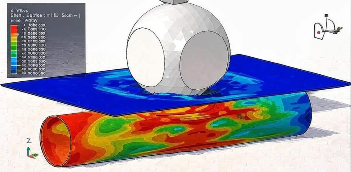
Because of their heterogeneous and anisotropic nature, the behavior of composites under mechanical, thermal, and environmental loads is complex. Traditional analytical methods are often insufficient to capture these complexities. Therefore, numerical simulation tools—most notably the Finite Element Method (FEM)—are essential for understanding and predicting the performance of composite structures.

Composite material analysis and simulation involves:

  • Micro-scale analysis: studying the behavior of fibers, matrix, and their interfaces.
  • Meso-scale analysis: examining representative volume elements (RVEs) to capture ply-level properties.
  • Macro-scale analysis: modeling the performance of entire composite laminates or structures.

Modern simulation software, such as Abaqus with the Composite Package, provides powerful tools for:
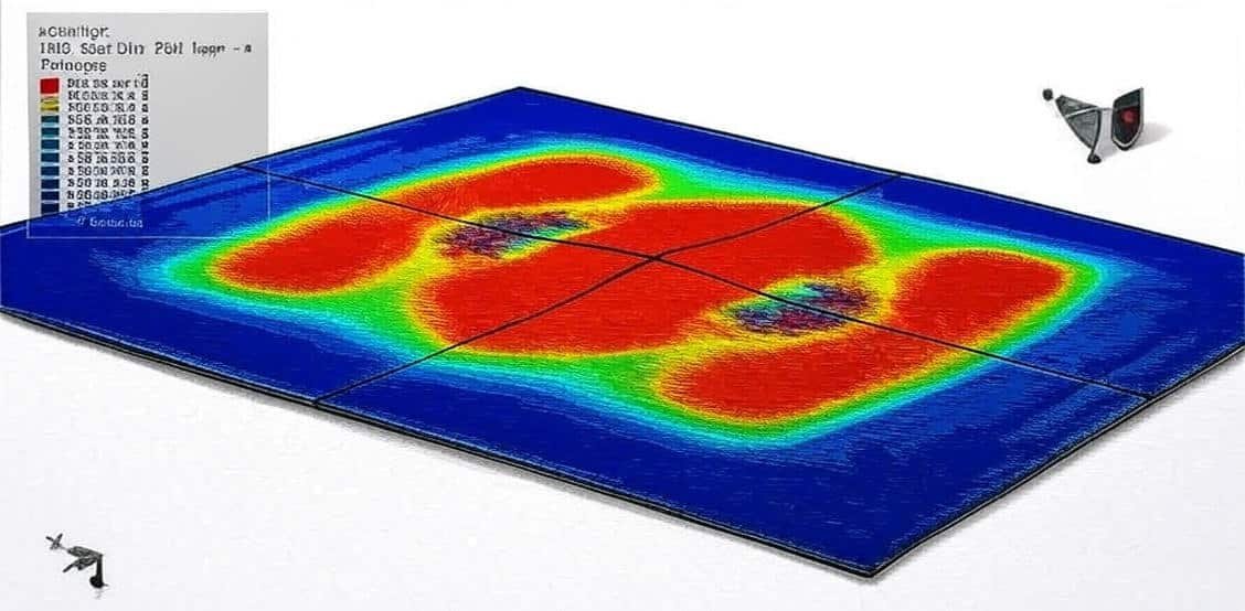
  • Defining complex layups and fiber orientations.
  • Evaluating stiffness, strength, and failure modes (e.g., delamination, matrix cracking, fiber breakage).
  • Simulating progressive damage and fatigue.
  • Optimizing composite designs for weight reduction and performance improvement.

Summary:
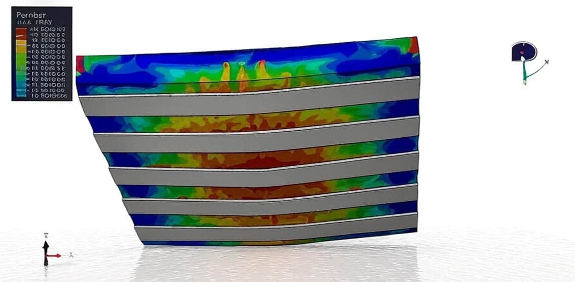
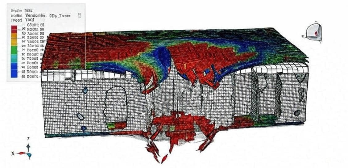
In Abaqus, the method for composite material analysis involves defining anisotropic properties, building the ply layup, using appropriate elements, applying loads and failure criteria, and running progressive damage simulations. This allows engineers to predict the strength, stiffness, delamination, and ultimate failure of composite structures with high accuracy.

By integrating material modeling, structural mechanics, and computational simulation, engineers and researchers can design safer, lighter, and more cost-efficient composite structures while minimizing the need for expensive experimental testing.

Course Content

Example-1: Finite element analysis of the seismic behavior of a CFRP-strengthened seismic-composite steel-concrete column
In this lesson, the finite element analysis of the seismic behavior of a CFRP-strengthened seismic-composite steel-concrete column is studied. The concrete and steel columns are modeled as three-dimensional solid parts. The steel reinforcements are modeled as wire parts. The CFRP box is modeled as a shell part. The frame column structure is composed of sections of steel-reinforced concrete and has been widely used in super-high building structures and large-span structures due to its high load-carrying capacity, good seismic performance, and other advantages. In practical engineering, the carbon fiber sheet has received considerable attention due to its high strength, lightweight, high corrosion resistance, ease of fabrication, etc. This effective strengthening method using composite steel-concrete structures has become more and more widely used in the United States, Canada, Japan, and, recently, Europe. In China, the research and application of carbon fiber reinforced polymer (CFRP) for strengthening reinforced concrete structures began in 1997. In this study, cyclic loading tests were performed on composite steel-concrete columns to investigate the effect of the strengthening of seismic-damaged composite steel-concrete with CFRP on the performance of frame columns. The tests included horizontal load testing, horizontal displacement testing, and recording of the load-displacement hysteresis loops of the specimen

  • Abaqus Files
  • Document
  • Tutorial Video
    29:29

Example-2: High velocity impact on CFRP-Aluminum foam-Aluminum honeycomb-CFRP panel
In this section, the high velocity impact on CFRP-Aluminum foam-Aluminum honeycomb-CFRP panel is investigated. The CFRP parts are modeled as three-dimensional parts with sixteen layers. The aluminum foam is modeled as a three-dimensional solid part. The aluminum honeycomb is modeled as a shell part. Fiber-reinforced composite sandwich structures have been increasingly used in many advanced engineering applications, from aircraft bodies, sports cars, ships, bridge decks, and piers, to beams and columns of buildings, due to their high specific strength, high stiffness, lightweight, and corrosion resistance. However, accumulated evidence shows their vulnerability when impacted by heavy objects, bird strikes, tool drops, and loadings due to collision incidents. Impact loads cause severe damage to sandwich structures internally and externally in terms of substantial reduction in the tensile, compressive, shear, and bending strength since the event is instantaneous and the corresponding load magnitude can be many times that of its static counterpart. equivalent. Therefore, new strategies and designs to improve the impact resistance of such structures have been continually proposed and refined, rendering them an active research topic. The Crushable foam and damage criterion are considered to model metal foam, like aluminum foam. The Johnson-Cook hardening and dynamic failure are used to model honeycomb behavior under severe load. The elastic and damage models are selected to define CFRP composite behavior.

Example-3: Analysis of the CFRP blanket effect on reducing the deformation of buried pipelines exposed to the subsurface explosion
In this case, the analysis of the CFRP blanket effect on reducing the deformation of buried pipelines exposed to the subsurface explosion is presented. The air, soil, and TNT are modeled as three-dimensional parts inside an Eulerian part. The steel pipe is modeled as a three-dimensional part. The CFRP blanket is modeled as three three-dimensional parts with some layers. Buried pipelines are vital arteries used to transport water, oil, and similar substances. Unfortunately, there have been different terrorist attacks against oil and gas pipelines in the last 28 years. This has highlighted the necessity of analyzing and designing pipelines that can 29 withstand such blast loads. The estimation of pipeline damage is a very complex work 30 because different factors, such as explosion, the transmission of energy to the soil and air, soil pipeline interaction, and pipeline behavior, affect the final results. Although analytical and empirical approaches have been widely used in explosion problems, numerical methods provide us with valuable information about the behavior of structural members with sophisticated behaviors. This study adopts the ideal gas equation of state to simulate air. The shaped charge is modeled using the Jones-Wikens-Lee (JWL) equation of state. This equation models the pressure induced by the release of the chemical energy of an explosion. This model is implemented using the so-called scheduled combustion structure in the sense that the explosion is not triggered via stressing explosive substances. Rather, the time traveling the explosion wave to each point is defined by the velocity of the explosion wave and the distance of each point from the explosion center. JWL equation of state can be written under the internal energy per unit mass of an explosive substance. Blast loads cause severe strains in pipes. Therefore, any model used for pipeline modeling should take strain rate into account. Johnson-Cook is a fit model for simulating the behavior of many materials, especially metals, under severe strain deformations. FRP is made of high-strength fibers inlaid in an epoxy resin substrate. GFRP is a conventional FRP composite produced as strips, sheets, tendons, or reinforcing columns. In addition to cost-effective execution advantage, FPRs show high strength, high formability, and remarkable energy absorption, before the failure point, behavior.

Example-4: Forming process of the steel-CFRP-steel composite
In this lesson, the forming process of the steel-CFRP-steel composite is studied. The two steel plates are modeled as a three-dimensional shell part. The CFRP core is modeled as a three-dimensional shell part with four layers. The die and punch are modeled as analytical rigid parts. The elastic-plastic material model is selected for the steel parts, and the lamina elasticity with Hashin’s damage criterion is selected to model the CFRP material. The dynamic explicit step with the mass scale technique is used to consider the dynamic process of forming. The surface-to-surface contact with the property is selected for the punch, die, and steel plates. The perfect contact is among the plates. The proper boundary conditions are assigned to the die and punch. In the context of scarcer fossil raw materials and rising fuel prices, lightweight designs are increasingly entering the automotive industry. One of the key objectives in the development of future car generations is the reduction of fuel consumption and, concomitantly, the reduction of pollutant and CO2 emissions. A reduction in the vehicle weight leads to a greater ratio of payload to deadweight and, in addition, functions such as acceleration and driving dynamics are better met. A lower mass results in lower acceleration, ascent, and rolling resistances. A common approach is the substitution of high-density materials, such as steel, with lighter, low-density materials with high strength, such as CFRP. Significant weight advantages can be realized by using composite materials. However, the high material costs and the necessity of employing manual manufacturing processes limit the use of just composites to the high-priced car segment. One promising approach is structural components in a multi-material design, such as hybrid parts made of high-strength steel with local CFRP reinforcements. Such hybrid components have cost advantages compared with exclusively CFRP components and can be reinforced in a load-adapted manner. An alternative, promising approach for the economic, automated mass production of lightweight structures with a high stiffness-to-weight ratio is the combination of high-strength steel alloys and CFRP prepregs in a special hybrid material – fiber-metal laminate (FML), which can be further processed by forming processes such as deep drawing. FML consists of metal sheet top layers with a CFRP core. The CFRP patches are chambered within the sheet metal layers and are not in direct contact with the tool surfaces. Compared to the forming of just composites, the forming process can be simplified, and the process chain gets shorter, which is significantly more economic. Fiber metal laminates also have the particular advantage that the mechanical properties of the components produced can be adjusted by the number of CFRP layers and the fiber orientation of the individual patches within the layers

Example-5: Blast explosion analysis of the composite panel(Steel-Aluminum-Ceramic-CFRP)
In this section, the blast explosion analysis of the composite panel(Steel-Aluminum-Ceramic-CFRP) is investigated. The steel and aluminum plates are modeled as a three-dimensional solid part. The silicon carbide or ceramic is modeled as a three-dimensional solid part. The CFRP is modeled as a three-dimensional solid part with four layers. The study of blast load, known as blast or explosion dynamics or terminal ballistics, has many crucial applications. An in-depth understanding of the deformation behavior of materials under blast loading helps not only in designing better products but, more importantly saving human life. Knowledge of material response under blast loading will help in estimating, enhancing, and extending the life and performance of any structure. The response of metals to applied loading not only depends on strain but also on other parameters such as temperature, pressure, strain rate, etc. To model steel and aluminum behavior under blast load, the Johnson-Cook plasticity and damage model is used. The Johnson-Cook (JC) model is a phenomenological model commonly used to predict the material response of metals subjected to high strain rate and impact loading. To model CFRP behavior elastic model as a lamina and Hashin’s damage criterion is selected. To model ceramic behavior under impact or severe blast load, Abaqus recommends some material models that are available in Abaqus CAE or through a code. The dynamic explicit step is appropriate for this type of analysis, and the mass scale technique is used to reduce the time of the simulation and create stability in the model. The perfect contact model is used to define interaction among the surfaces of the parts. The CONWEP blast load procedure is selected to define the blast load condition.

Example-6: Low-energy impact on a concrete slab with pre-tensioned bars reinforced with GFRP
In this case, the low-energy impact on a concrete slab reinforced with pre-tensioned bars and GFRP is presented. Concrete is modeled as a three-dimensional solid part. The GFRP part is modeled as a planar shell part. The steel bars are modeled as three-dimensional wire parts, and the projectile as a discrete rigid part. The model is a continuum, plasticity-based, damage model for concrete. It assumes that the two main failure mechanisms are tensile cracking and compressive crushing of the concrete material. To model concrete behavior under impact load, the CDP model is selected. Damage initiation refers to the onset of degradation at a material point. In Abaqus, the damage initiation criteria for fiber-reinforced composites are based on Hashin’s theory. These criteria consider four different damage initiation mechanisms: fiber tension, fiber compression, matrix tension, and matrix compression. Hashin damage criterion is selected for the GFRP with 8 different layers to consider the damage during the impact. The elastic-plastic property is also used to model the behavior of steel bars. A dynamic explicit step with a mass scale to make acceleration in the simulation has been considered. The general contact algorithm with contact property is defined for all parts; the steel bars are embedded inside the concrete slab, and a tie constraint is used between the concrete slab and the GFRP plate. The boundary condition is assigned to the concrete slab, and the velocity to the projectile. The stress is applied to steel bars to be pre-tensioned. This can be done with temperature or stress.

Example-7: Dynamic bending analysis of a UHPC beam reinforced with GFRP bars
In this lesson, the dynamic bending analysis of a UHPC beam reinforced with GFRP bars is studied. The Ultra-High-Performance concrete beam is modeled as a three-dimensional solid part. The cohesive layer as an interface between UHPC and GFRP bar is modeled as a three-dimensional solid part. The GFRP is modeled as a three-dimensional solid part, and the two rigid parts have been used to apply the load. To model UHPC material, the Concrete Damaged Plasticity model is used. This hardening model is used both compression and tension data to simulate the UHPC behavior under dynamic bending load. To model the cohesive layer, the elastic data type traction, and also the traction-separation law to consider failure are used. To model GFRP behavior, the elastic data as an engineering constant is selected. The dynamic explicit step is appropriate for this type of analysis because of the large deformation and separation that happen during the bending between the UHPC and the GFRP bars. The general contact algorithm with friction as a contact property is selected to consider all contacts. The perfect or ideal contact is applied to the surface of the concrete and the cohesive layer of GFRP and cohesive layer.

Example-8: Modeling of the reinforced brick masonry beams using GFRP sheet
In this section, the modeling of the reinforced brick masonry beams using GFRP sheet is investigated. The bricks are modeled as three-dimensional solid parts, and GFRP sheets are modeled as three-dimensional shell parts. Natural stone structures represent the largest part of the construction heritage in the world, such as bridges, civil and worship buildings, or historical monuments. The natural stone is preferred for many reasons, such as beauty, accessibility, hardness, durability, strength, and sustainability. It is necessary to have a good understanding of the mechanical behavior of stone structures. Their main characteristics are high compressive strength and almost null tensile strength due to the joints. Therefore, in historical structures, the use of stone is mostly restricted to members mainly working in compression. The reinforcement of masonry structures is one of the most frequently used practices in the restoration of historical buildings to enhance their resistance. It can be performed using steel bars, rings, and/or composite materials. In the last two decades, composite materials, like FRP, have been increasingly considered for strengthening and repairing both modern and historic masonry constructions. FRP is are excellent candidate for strengthening because of the high tensile strength they provide, their resistance to corrosion, and their easy handling. Several papers have addressed the strengthening of masonry with carbon and glass fiber-reinforced composites. The elastic behavior with Concrete Damaged Plasticity is used for the bricks. The elastic behavior lamina type with Hashin’s damage criterion is used for the GFRP sheets. The explicit step with general contact is used. The contact between blocks and the GFRP sheet is assumed to be a perfect contact. The mortar is used as a cohesive surface interaction by using cohesive behavior and damage parameters.

Example-9: Blast load analysis of a sandwich panel(GFRP+Foam)
In this case, the blast load analysis of a sandwich panel(GFRP+Foam) is done through a comprehensive tutorial. Sandwich panels based on two relatively stiff face sheets separated by a foam core are commonplace in the marine industry, for example, in surfboard and yacht construction. Lightweight sandwich materials are attractive options for the transport industry, which is seeking to improve fuel economy and speed whilst reducing harmful emissions. At the same time, there is a competing requirement for vehicles to be protected from explosions, which traditionally involves the use of strong, relatively ductile metals such as armour steel. To model GFRP, Hashin’s damage criterion and for foam Crushable material model have been used. A dynamic explicit procedure is appropriate for this type of analysis. For modeling the detonation behavior of TNT, the CONWEP procedure is selected, and during the analysis blast wave creates damage over the facial composite layouts, but after that, the foam core absorbs the detonation energy, and the back plate composites stay intact. The foam has a large deformation because of absorbs energy

Example-10: Durability analysis of the GFRP-SFRSC concrete adhesively bonded connection
In this lesson, the durability analysis of the GFRP-SFRSC concrete adhesively bonded connection is studied. The GFRP beam and the steel fiber-reinforced self-compacting concrete (SFRSCC) are modeled as three-dimensional solid parts. Fiber-reinforced polymer (FRP) materials are becoming increasingly considered as an alternative to traditional materials for civil engineering structural applications, due to their high strength, low self-weight, ease of installation, electromagnetic transparency, and good chemical and corrosion resistance. With low maintenance requirements, these materials offer a promising alternative for the development of more durable and sustainable structures. Pultruded glass-fiber reinforced polymer (GFRP) profiles combine the above-mentioned advantages with moderately low manufacturing costs. However, GFRP profiles present low elasticity and shear moduli, being relatively deformable and prone to instability phenomena. To overcome those limitations, several hybrid structural solutions have been proposed, combining GFRP profiles with concrete elements. In some hybrid solutions, adhesively bonded (epoxy) connections are used to enhance the composite action, thus preventing the occurrence of interconnection slip at the GFRP-concrete interface. In some cases, adhesive bonding is complemented with mechanical connection systems, which generally provide a negligible contribution to the stiffness, but can act as a redundant (“backup”) connection in case of adhesive failure or long-term degradation. An example of such a hybrid system is the São Silvestre footbridge, which comprises two pultruded GFRP girders adhesively bonded (with epoxy) and bolted to a very thin deck made of steel-fibre reinforced self-compacting concrete (SFRSCC). The Concrete Damage Plasticity material model is a good choice to define the non-linear behavior of the SFRSCC slab. To define GFRP, the elastic data as an engineering constant is considered. The dynamic explicit step with cohesive interaction as the behavior of the interface between concrete and GFRP is selected.

Example-11: Four-point bending modeling of a concrete beam reinforced with steel bar and BFRP
In this section, the four-point bending modeling of a concrete beam reinforced with steel bar and BFRP is investigated. The concrete beam is modeled as a three-dimensional solid part. The Basalt Fiber reinforced Plastic(BFRP) is modeled as a shell part with four layers. The strips and bars are modeled as three-dimensional wire part. Some rigid bodies also used as hydraulic jack to apply load. The Concrete Damaged Plasticity is used to model concrete beam behavior. The model is a continuum, plasticity-based, damage model for concrete. It assumes that the main two failure mechanisms are tensile cracking and compressive crushing of the concrete material. The steel material with elastic and plastic models is selected for the strips and bars. To model the BFRP composite, elastic data lamina type and Hashin’s Damage criterion is used. Damage initiation refers to the onset of degradation at a material point. In Abaqus the damage initiation criteria for fiber-reinforced composites are based on Hashin’s theory. These criteria consider four different damage initiation mechanisms: fiber tension, fiber compression, matrix tension, and matrix compression. The general contact capability with some changes in the convergence model to avoid early not convergence is selected. The surface-to-surface contact algorithm is selected to define contact between rigid bodies and a concrete beam. The embedded region constraint is used for the steel bars and strips. The perfect contact is assigned to the interface zones between concrete and BFRP.

Example-12: Air blast analysis of the UHPC slab reinforced with BFRP composite
In this case, the air blast analysis of the UHPC slab reinforced with BFRP composite is presented. The Ultra-High-Performance-Concrete is modeled as a three-dimensional solid part. The Basalt fiber reinforced plastic(BFRP) is modeled as a shell part with four layers. The Concrete-Damaged Plasticity is used to model the non-linear behavior of the UHPC. In this model, the tensile and compression data are defined separately, and tensile and compression damage can be used. Laminated fiber reinforced composite materials are increasingly used in various industries such as aerospace, military, marine, car manufacturing, etc, due to their superior specific strength and stiffness, convenient fabrication of complicated products and structures, corrosion and environmental resistance, as well as their competitive cost for fabrication. The elastic model lamina type and Hashin’s damage criterion are used to model BFRP behavior under the blast load. The dynamic explicit step is appropriate for this type of analysis. The ideal contact is selected between the UHPC surface and the BFRP composite parts. The COWEP blast explosion procedure is considered. In this way, the amount of the TNT and its locations should be defined.

Example-13: Bending test analysis of the UHPFRC beam reinforced with BFRP lamina
In this section, the bending test analysis of the UHPFRC beam reinforced with BFRP lamina is investigated. The UHPFRC beam is modeled as a three-dimensional solid part. The BFRP lamina with eight layers is modeled as a shell part. The steel bars and strips are modeled as a three-dimensional wire part. The model is a continuum, plasticity-based, damage model for concrete. It assumes that the two main failure mechanisms are tensile cracking and compressive crushing of the concrete material. The concrete damaged plasticity model provides a general capability for modeling concrete and other quasi-brittle materials in all types of structures. The CPD model can also consider the tension and compression damage for the UHPFRC beam. The steel material with elastic and plastic behavior is selected for the bars and strips. The BFRP lamina is modeled as a conventional shell section with eight layers and the elastic material lamina type, and also Hashin’s damage criterion is used. The general static step is appropriate for this type of analysis. The bars and strips are embedded inside the concrete beam. The perfect contact is assumed between the BFRP parts and the concrete. The surface-to-surface contact with friction as a contact property is selected to define the contact between the rigid body and the concrete beam.

Example-14: Blast resistance analysis of an RC slab strengthened with AFRP
In this lesson, the blast resistance analysis of an RC slab strengthened with AFRP composite is studied. The concrete slab is modeled as a three-dimensional solid part, the AFRP is modeled as a four-layer composite with a shell part, and the embedded beam inside the concrete host is modeled as a wire part. Due to the increase of terrorist attacks and accidental explosions in current society, the RC structure, which is the principal construction of civilian buildings and military construction, tends to be exposed to blast loadings. The short-duration and high magnitude of blast loading can induce severe damage to the RC structure. Generally, it’s known that concrete has a relatively high capacity to resist blast loads. In recent decades, the external bonding of fiber-reinforced polymer (FRP) strips to improve the blast resistance has received great interest. The technique of external bonding FRP has many advantages, such as high strength, lightweight, lower cost, excellent corrosion resistance, convenient construction, etc. Aramid Fiber Reinforced Plastic (AFRP) is a relative newcomer to FRP composites, compared with CFRP and GFRP. Besides the common properties of all the FRP materials, it has some other unique features such as superior dielectric properties, high heat and flame resistance, better corrosion, impact, and fatigue resistance, short curing time, etc. To model steel behavior, elastic and Johnson-Cook plasticity and damage data were used. The AFRP is modeled as a lamina with Hashin’s damage criterion. To model concrete behavior under massive pressure like detonation, the JH2 material model, instead of CDP or Brittle cracking, was used. The JH2 model can predict damage propagation in good order, and the result of that is reliable. The dynamic explicit step is appropriate for this type of analysis. The beam is used as an embedded region inside the concrete. The CONWEP blast load procedure is used to define the TNT explosion near the concrete slab. To define concrete-AFRP interaction, cohesive surface behavior with damage data is used.

Example-15: High-velocity impact of a steel rod on the composite panel(Steel-Ceramic-AFRP)
In this case, the high-velocity impact of a steel rod on the composite panel(Steel-Ceramic-AFRP) is presented. The steel rod and steel cover are modeled as a three-dimensional solid part. The ceramic part is modeled as a three-dimensional solid part. The Aramid Fiber Reinforced Plastic(AFRP) is modeled as a three-dimensional solid part with four layers. The steel material with Johnson-Cook plasticity and damage is used to model the projectile and the steel cover layer. The Johnson-Cook plasticity model is a particular type of Mises plasticity model with analytical forms of the hardening law and rate dependence. It is suitable for high-strain-rate deformation of many materials, including most metals, and is typically used in adiabatic transient dynamic simulations. To model AFRP composite material, the lamina elastic behavior and Hashin’s damage criterion are selected. Abaqus offers a damage model enabling you to predict the onset of damage and to model damage evolution for elastic-brittle materials with anisotropic behavior. The model is primarily intended to be used with fiber-reinforced materials since they typically exhibit such behavior. Damage initiation refers to the onset of degradation at a material point. In Abaqus, the damage initiation criteria for fiber-reinforced composites are based on Hashin’s theory. To model ceramic behavior, the Johnson-Holmquist-Beissel model is used. The JHB model consists of three main components: a representation of the deviatoric strength of the intact and fractured material in the form of a pressure-dependent yield surface, a damage model that transitions the material from the intact state to a fractured state, and an equation of state (EOS) for the pressure-density relation that can include dilation (or bulking) effects as well as a phase change. The dynamic explicit step is appropriate for this type of analysis. The general contact algorithm is selected to consider all contacts in the contact domain. The perfect contact is assumed between the ceramic-AFRP and the ceramic-steel cover.

Exampe-16: Three-point bending test of the UHPC beam reinforced with Jute-Epoxy lamina
In this lesson, the three-point bending test of the UHPC beam reinforced with Jute-Epoxy lamina is studied. The UHPC beam is modeled as a three-dimensional solid part. The Jute-Epoxy lamina is modeled as a three-dimensional shell part with four layers. A rigid body shell part is used to apply displacement as a load in the load section. Recently, the use of ultra-high performance concrete (UHPC) for the rehabilitation and strengthening of reinforced concrete (RC) beams has been considered by researchers and engineers. The material properties of UHPC, such as super-high tensile and compressive strengths, ductility, and good durability, make UHPC attractive for various engineering structures, especially in bridge engineering. The popularly employed Concrete Damaged Plasticity (CDP) model available in ABAQUS was used to model the nonlinear behavior of UHPC in compression and tension. The CDP model can predict the tensile and compressive damage during the analysis. Jute-based green composites are emerging materials due to their certain attractive properties like appropriate strength-to-weight ratio, high damping ratio, low price, and corrosion resistance. There is a growing interest in natural and enjoyment-friendly materials and the desire to lessen the cost of synthetic fibers, which are being utilized generally in the synthesis of polymer composites. Numerous scientists have started working on natural fiber composites (i.e., biocomposites)because these composites are now widely used in the automotive industry and in different interior and exterior car parts. To model Jute-epoxy lamina, a conventional shell with four layers is used. The general static step with some changes in the convergence model to avoid early non-convergence is selected. The surface-to-surface contact with friction as a contact property between the rigid body and the concrete part is used.

Example-17: Jute-Epoxy retrofit of the concrete column under dynamic compression
In this section, the jute-Epoxy retrofit of the concrete column under dynamic compression is investigated. The concrete column is modeled as a three-dimensional solid part. The just-Epoxy part is modeled as a three-dimensional shell. A rigid body is used as the hydraulic jack. The Concrete Damaged Plasticity model is used to model concrete column behavior under compression load. The model is a continuum, plasticity-based, damage model for concrete. It assumes that the two main failure mechanisms are tensile cracking and compressive crushing of the concrete material. This model uses tensile and compressive stress-strain separately and can also predict tensile and compressive damage. The conventional shell with four different layers is used to model the Jute-Epoxy lamina. The elastic properties as an engineering constant are selected for the Jute-Epoxy. The dynamic explicit step with the mass scale technique is used to make a quasi-static situation. The general static step can also be used also but because of the non-convergence, it needs plenty of time to complete the simulation; on the other hand, the explicit step is much faster than the static one. The general contact capability with frictional behavior is selected. The perfect contact is assumed between Jute-Epoxy and the concrete column.

Example-18: Compression test analysis of the short concrete column reinforced with Banana-Epoxy lamina
In this case, the compression test analysis of the short concrete column reinforced with Banana-Epoxy lamina is presented. The concrete column is modeled as a three-dimensional solid part. The Banana-Epoxy lamina is modeled as a three-dimensional shell part. The steel bars and strips are modeled as three-dimensional wire parts. The Concrete Damaged Plasticity model is used for the concrete column. The model is a continuum, plasticity-based, damage model for concrete. It assumes that the two main failure mechanisms are tensile cracking and compressive crushing of the concrete material. The concrete damaged plasticity model provides a general capability for modeling concrete and other quasi-brittle materials in all types of structures. To model steel behavior, an elastic-plastic material model is selected. To model the Banana-Epoxy lamina, the composite shell with different fiber orientations is used. The general static step is appropriate for this type of Analysis. The perfect contact is assumed between the composite parts and the concrete column. The steel reinforcements are embedded inside the concrete host. The general contact algorithm is selected to consider all contacts in the contact domain.

Example-19: Air blast analysis of an RC beam reinforced with Banana-Epoxy lamina
In this lesson, the air blast analysis of an RC beam reinforced with Banana-Epoxy lamina is studied. The concrete beam is modeled as a three-dimensional solid part. The bar and strip are modeled as a three-dimensional wire part. The Banana-Epoxy part is modeled as a three-dimensional shell with eight layers. To model concrete behavior under severe compression load, such as high velocity impact or blast explosion, Abaqus has several material models that are suitable for this analysis. We can use a code to write a new material model, or we can use the input file capability to consider a new material model. To model Banana-Epoxy material, the elasticity-engineering constant type is selected. Eight conventional shell layers with different fiber orientations are used. To model the bar and strip, the steel material with elastic-plastic behavior is selected. The dynamic explicit step is appropriate for this type of analysis. The steel reinforcements are considered as an embedded region inside the concrete host. The contact between the concrete beam and the Banana-Epoxy lamina is assumed as a perfect contact.

Example-20: High-velocity impact Modeling on the Aluminum-Bamboo sandwich panel
In this section, the High-velocity impact Modeling on the Aluminum-Bamboo sandwich panel is investigated. The aluminum plate is modeled as a three-dimensional solid part. The bamboo plate is modeled as a shell part with thirty-two layers with different fiber angle. The projectile is modeled as a three-dimensional rigid shell part. The configuration of a sandwich panel, which combines the advantages of joining two thin, stiff, and strong skins to a thick and low-density core, results in superior crashing characteristics and impact resistance under out-of-plane loading when compared to single solid components. Sandwich structures are, however, susceptible to considerable damage during manufacture, transport, installation, and service, which is caused by impacts from external objects, such as the collision of flying debris, dropped tools during maintenance, bird strikes, and even rain hail. To model aluminum behavior under high-velocity impact, the Johnson-Cook plasticity model is selected. The Johnson-Cook plasticity model is a particular type of Mises plasticity model with analytical forms of the hardening law and rate dependence, and is suitable for high-strain-rate deformation of many materials, including most metals. To consider the damage which happens during the analysis, the Jonson-Cook damage model is also used. Damage initiation refers to the onset of degradation at a material point. In ABAQUS, the damage initiation criteria for fiber-reinforced composites are based on Hashin’s theory. These criteria consider four different damage initiation mechanisms: fiber tension, fiber compression, matrix tension, and matrix compression. The bamboo is modeled as 32 conventional layers with different orientations for the fiber. A dynamic explicit step is so appropriate for this type of analysis. A general contact algorithm (Explicit) accessible in the Abaqus/Explicit interaction type is used in this analysis to define the contact between components. The cohesive contact method between the aluminum and bamboo is considered by using stiffness in three directions, damage, and fracture energy.

Example-21: Bending test analysis of the foamed concrete beam reinforced with bamboo fiber
In this case, the bending test analysis of the foamed concrete beam reinforced with bamboo fiber is done. The foamed concrete part is modeled as a three-dimensional solid part. The bamboo composite is modeled as a three-dimensional shell part with some layers. The steel reinforcements are modeled as the wire part. Construction materials using concrete are the primary building element of structures worldwide at present. The application of concrete in civil engineering is vast, ranging from the construction of bridges, dams to roads and tall buildings. The high demand for concrete can be attributed to its high durability, strength, moldability, and relative economy compared with other traditional materials. Ever since the development of concrete, many types of concrete have been manufactured. One of them is foamed concrete. It is a type of lightweight concrete; also, the bamboo, a very abundant natural resource in tropical regions, has been exploited as a back reinforcement. The Concrete Damaged Plasticity model is selected for the foamed concrete material to represent its correct behavior under the bending test. The elastic-plastic material model is considered for the steel reinforcements. The elastic model with a damage criterion is used for the bamboo fiber composite under the bending load. The general static step with some changes in the convergence method has been selected. The perfect contact is assumed between the layers of the parts.

Example-22: Simulation of the air blast load over a composite panel(Aluminum+bamboo fiber)
In this lesson, the simulation of the air blast load over a composite panel(Aluminum+bamboo fiber) is studied. Because of the symmetry circumstance, one quarter of the geometries is modeled. The aluminum plates are modeled as a three-dimensional solid part. The bamboo plate, as a core of the composite panel, is modeled as a three-dimensional shell part with sixteen layers. To model aluminum behavior under high-velocity impact, the Johnson-Cook plasticity model is selected. The Johnson-Cook plasticity model is a particular type of Mises plasticity model with analytical forms of the hardening law and rate dependence, and is suitable for high-strain-rate deformation of many materials, including most metals. To consider the damage that happens during the analysis, the Jonson-Cook damage model is also used. Damage initiation refers to the onset of degradation at a material point. In ABAQUS, the damage initiation criteria for fiber-reinforced composites are based on Hashin’s theory. These criteria consider four different damage initiation mechanisms: fiber tension, fiber compression, matrix tension, and matrix compression. For the Bamboo member, sixteen layers with different orientations of the fiber are considered.

Example-23: Numerical investigations of the S-Glass/Polyester composite laminate plate under low-energy impact
In this section, the numerical investigations of the S-Glass/Polyester composite laminate plate under low-energy impact are presented. With the growing use of composites in military, air vehicles, and naval structures, sporting goods, and the power industry, the comprehension of impact mechanisms and dynamic behavior is critical to composite designers and end users. A wealth of knowledge has been published on the dynamic impact response of composite materials and structures. Yet, with continually emerging materials and processes, there is a lack of systematic structure-property-performance relationships that provide guidelines on the dynamic impact behavior of composites. The impact response of materials is generally categorized into low, intermediate, high or ballistic, and hyper velocity regimes. The ability to predict the extent of damage and compression after impact of a composite structure can potentially lead to the exploration of a larger design space without incurring significant time and cost penalties. In this simulation, Numerical investigations of S-Glass/Polyester composite laminate plate under low-energy impact have been conducted. A conventional shell composite layout has been used to define composite layouts with different angles. Impact problems involve strong loading with a complex induced damage. To reproduce and hence analyse the complex phenomena occurring during the impact, numerical approaches are more adapted. The finite element method remains the most commonly adopted method to simulate impact problems in various engineering fields. The Abaqus/Explicit FE code, with its dynamic explicit solver, is well-suited for simulating such problems. The most commonly used in FE simulations of composite materials are layered shells, layered solids, stacked solid elements, and stacked or layered continuum shells. The plate is modelled with material as a lamina with anisotropic elasticity coupled with Hashin’s damage criteria. There are interacting failure criteria where more than one stress component has been used to evaluate the different failure modes. During the impact, the projectile with an initial velocity causes damage and stress in the composite plate

Example-24: Analysis of the composite Pipe(Aluminum-Bamboo fiber-Aluminum) under internal blast
In this case, the analysis of the composite Pipe(Aluminum-Bamboo fiber-Aluminum) under internal blast is investigated. The configuration of a composite pipe, which combines the advantages of joining two thin, stiff, and strong skins to a thick and low-density core, results in superior crushing characteristics and impact or blast resistance under out-of-plane loading when compared to single solid components. In this context, bamboo, a very abundant natural resource in tropical regions, has been exploited as a core material in composite pipes. To model aluminum under severe blast load, the Johnson-Cook hardening and damage model is selected. Abaqus/Explicit provides a dynamic failure model specifically for the Johnson-Cook plasticity model, which is suitable only for high-strain-rate deformation of metals. This model is referred to as the “Johnson-Cook dynamic failure model.” Abaqus/Explicit also offers a more general implementation of the Johnson-Cook failure model as part of the family of damage initiation criteria, which is the recommended technique for modeling progressive damage and failure of materials. The Hashin damage model is considered for the bamboo fiber pipe. Damage initiation refers to the onset of degradation at a material point. In Abaqus, the damage initiation criteria for fiber-reinforced composites are based on Hashin’s theory. These criteria consider four different damage initiation mechanisms: fiber tension, fiber compression, matrix tension, and matrix compression.

Example-25: SPH explosion analysis of a composite column(Steel cover+Concrete+CFRP I-shape beam)
In this lesson, the SPH explosion analysis of a composite column(Steel cover+Concrete+CFRP I-shape beam) is studied. The steel cover and CFRP I-shaped beam are modeled as three-dimensional shell parts. The concrete and TNT are modeled as three-dimensional solid parts. To model steel box behavior under severe load, the Johnson-Cook hardening and damage are selected. The Johnson-Cook model is a plasticity model that is based on Mises plasticity with closed-form analytical equations specifying the hardening behavior and the strain-rate dependence of the yield stress. The Jones-Wilkins-Lee (JWL) equation of state (EOS) has long been used to accurately calculate the Chapman–Jouguet (C-J) state of condensed phase explosive detonation waves and the subsequent expansion of the reaction products as they do work on surrounding materials. This material model is selected to convert chemical energy during the explosion to mechanical pressure. In solid mechanics, the Johnson–Holmquist damage model is used to model the mechanical behavior of damaged brittle materials, such as ceramics, rocks, and concrete, over a range of strain rates. Such materials usually have high compressive strength but low tensile strength and tend to exhibit progressive damage under load due to the growth of microfracture. The JH2 model is used to define concrete in this tutorial. The Hashin criterion identifies four different modes of failure for the composite material. The four modes are tensile fiber failure, compressive fiber failure, tensile matrix failure, and compressive matrix failure. To model the CFRP I-shaped beam, the Hashin damage model is considered.

Example-26: Air blast explosion near a composite GLARE panel
In this case, the air blast explosion near a composite GLARE panel is presented. Both aluminum lathe parts are modeled as three-dimensional solid parts. The four glass fiber layers are modeled as three-dimensional solid parts. Because of the symmetry, one-quarter of the whole model is considered. The Johnson-Cook hardening and damage are selected to model aluminum behavior under severe load. Johnson-Cook hardening is a type of isotropic hardening where the static yield stress is assumed to be of the form. where the equivalent plastic strain and A, B, n, and m are material parameters measured at or below the transition temperature. The Johnson-Cook criterion is a special ductile damage initiation criterion in which the equivalent plastic strain at the onset of damage is given as an analytical function of the stress triaxiality. The Hashin damage model for the continuum part is considered to model the glass fiber. The Hashin criterion identifies four different modes of failure for the composite material. The four modes are tensile fiber failure, compressive fiber failure, tensile matrix failure, and compressive matrix failure

Example-27: Impact analysis on the CFRP-PEEK-ceramic-gelatin composite for finding behind the armor trauma
In this lesson, the impact analysis on the CFRP-PEEK-ceramic-gelatin composite for finding behind the armor trauma is studied. The CFRP is modeled as a three-dimensional shell part. The polyether-ether-ketone(PEEK) is modeled as a thin solid layer to protect the other layers. The silicon carbide or ceramic is modeled as a three-dimensional solid layer in the middle. The gelatin or human tissue is modeled as a three-dimensional solid layer as a back plate. The projectile is modeled as a rigid body. To model CFRP material as the first layer of the panel, some layers with elastic properties and Hashin’s damage criterion are selected. A ceramic-based armor system must arrest bullet penetration and dissipate a large amount of impact energy. Taking the total linear momentum transferred to the wearer of a ceramic armor as a measure of the behind-armor ballistic/blunt trauma (BABT), we study the effect on the BABT of adding a thin polyether-ether-ketone (PEEK) layer on the face of a Silicon Carbide (SiC) ceramic target under blast load to investigate the effect of detonation on the human tissue. The SiC is modeled as a Johnson-Holmquist (JH-2) material model. The SiC material is very hard and mainly used under compressive load conditions, and can only sustain very little tension. Typical applications include bulletproof vests and car brakes due to their high endurance. The strength has a dependence on pressure. In high-speed impact applications, damage to the material plays an important role in the evolution of the strength. The totally failed silicon carbide will not sustain any load. The JH-2 model assumes that the damage variable increases progressively with plastic deformation. To model PEEK, the Johnson-Cook hardening and damage model is selected. To model gelatin elastic-plastic material format is acceptable. All materials are assumed to be homogeneous and isotropic. In order to quantify the momentum transferred to the wearer of the ceramic armor, the PEEK layer is bonded to the ceramic. To model gelatin behavior, the elastic-plastic model with the equation of state is considered.

Reviews

No Review Yet
No Review Yet
279,00 598,00
22 people watching this product now!

Material Includes

  • 1- Abaqus Files
  • 2- Paper and Document
  • 3- Tutorial Videos

Audience

  • 1- Mechanical Engineering
  • 2- Composite Material Engineering
  • 3- Aerospace Engineering

Related  Products

See more

Want to receive push notifications for all major on-site activities?