

Engineering Downloads
Let’s Learn and Collaborate
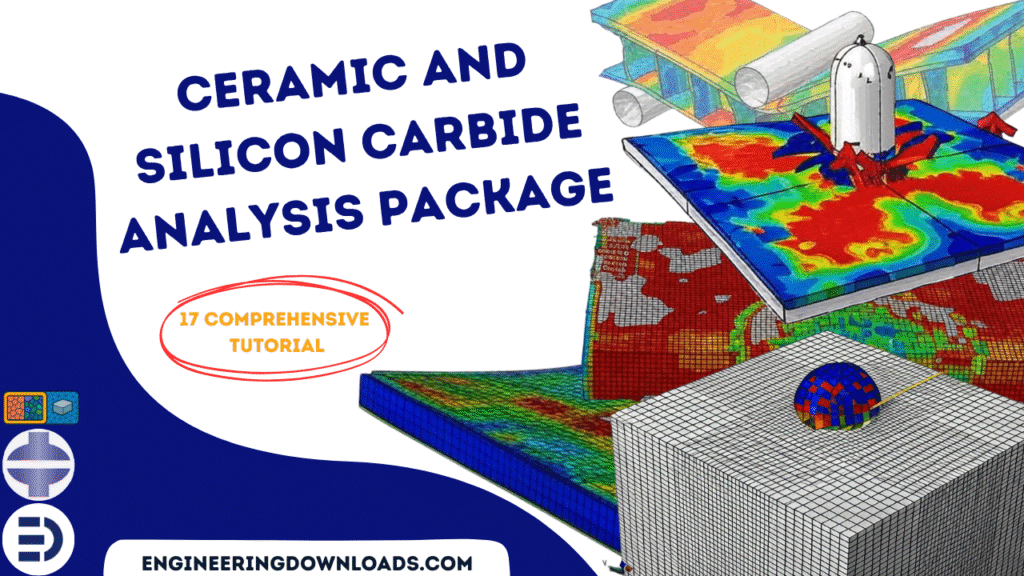
Ceramic materials, particularly Silicon Carbide (SiC), play a crucial role in advanced engineering applications where high strength, stiffness, wear resistance, and thermal stability are required.
However, their brittle nature and complex failure mechanisms make experimental characterization difficult and expensive.
Therefore, Finite Element Method (FEM) simulation has become an essential tool for analyzing the mechanical, thermal, and multiphysics behavior of ceramics and SiC under various conditions.
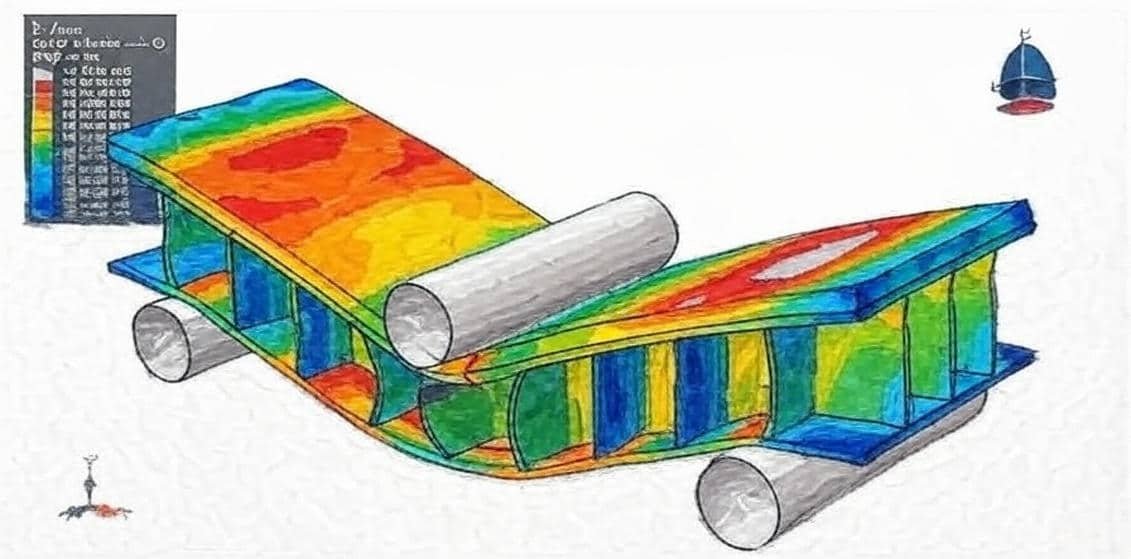
This package includes 17 detailed tutorials that comprehensively explain ceramics and silicon carbide. Various material models, such as JHB, JH2, ductile damage, the Drucker–Prager yield criterion, EOS, and others, are presented through simulations covering a wide range of scenarios, including high- and low-velocity impact, cold spray, pull-out tests, chip formation processes, bending, blast, and explosion analyses.
Ceramics are inorganic, non-metallic materials with:
Among ceramics, Silicon Carbide (SiC) stands out due to:
These characteristics make SiC ideal for applications in aerospace, defense, power electronics, and high-temperature structural components.
The Finite Element Method (FEM) is a numerical technique used to approximate solutions to complex problems in engineering and physics.
In the context of ceramics and SiC, FEM enables:
Because ceramics often fail catastrophically, FEM helps predict critical stress regions and avoid failure through virtual testing before physical fabrication.
A typical FEM analysis of ceramic or SiC materials includes the following steps:
Create a 2D or 3D model of the component — e.g., turbine blade, plate, coating, or composite structure.
Define temperature-dependent material properties such as:
For SiC, nonlinear or anisotropic models may be applied for high-temperature or composite variants (e.g., SiC–SiC).
Discretize the model into finite elements (tetrahedral, hexahedral, etc.).
A finer mesh is applied in regions expected to experience high stress gradients or cracks.
Apply:
FEM has become an indispensable tool for understanding and optimizing the performance of ceramic and Silicon Carbide materials.
It enables engineers to predict failure modes, analyze thermal-mechanical coupling, and design reliable high-temperature components with minimal experimental cost.
Ongoing advancements in computational power and fracture modeling continue to expand FEM’s capability to accurately simulate the complex behavior of brittle ceramic materials like SiC.


Abaqus
€97,00 €54,00

Engineering files
€60,00 €50,00

Abaqus
€146,00 €89,00

Abaqus
€85,00 €47,00

Abaqus
€78,00 €39,00
See more

Want to receive push notifications for all major on-site activities?


