Engineering Downloads

Let’s Learn and Collaborate

Engineering Downloads

Bolt Analysis Package in Abaqus

199,00 425,00
199,00 425,00
22 people watching this product now!

Material Includes

  • 1- Abaqus Files
  • 2- Document
  • 3- Tutorial Videos

Audience

  • 1- Mechanical Engineering
  • 2- Civil Engineering
  • 3- Structural Engineering
  • 4- Manufacturing Engineering

What You Will Learn?

  • In this course, you'll learn all things about static and dynamic analysis of the bolt in Abaqus, such as tension, compression, bolt load, failure, damage, JC material, ductile damage, shear failure, fire, thermal model, and more, through 17 practical and comprehensive tutorials.

About Course

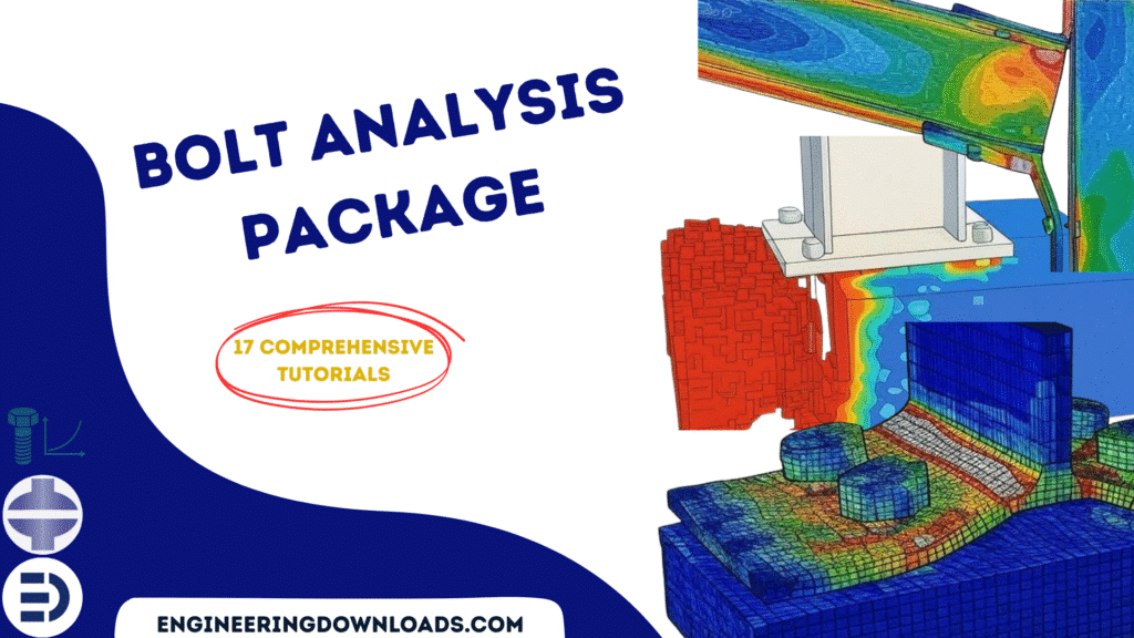
Introduction to Bolt Analysis and Simulation

Bolts are among the most common fastening elements in engineering, used to join parts in machinery, structures, and vehicles. Although they may seem simple, bolts are often critical for safety and reliability, failure of a single bolt can cause entire systems to fail.

To ensure performance, engineers use bolt analysis and simulation techniques to predict how bolts behave under different conditions.

This package includes 17 tutorials that cover everything about bolt simulation in Abaqus.


1. What is Bolt Analysis?

Bolt analysis is the process of evaluating the strength, stiffness, and load distribution of bolted joints. The goal is to ensure the bolt (and the joint) can withstand:

  • Preload (tightening force): The clamping force applied when tightening.
  • External loads: Forces, moments, and vibrations acting on the joint during service.
  • Stress concentrations: Localized stresses around threads and contact surfaces.
  • Fatigue: Cyclic loading that may cause failure over time.

Key parameters considered:

  • Bolt preload (torque–tension relationship).
  • Tensile and shear stresses.
  • Thread and bearing stresses.
  • Joint stiffness vs. bolt stiffness.
  • Safety factors (static and fatigue).

2. Why Simulate Bolted Joints?

Analytical formulas can estimate stresses, but simulation (often via Finite Element Analysis, FEA) gives a more accurate picture, especially for complex assemblies.

Simulation helps to:

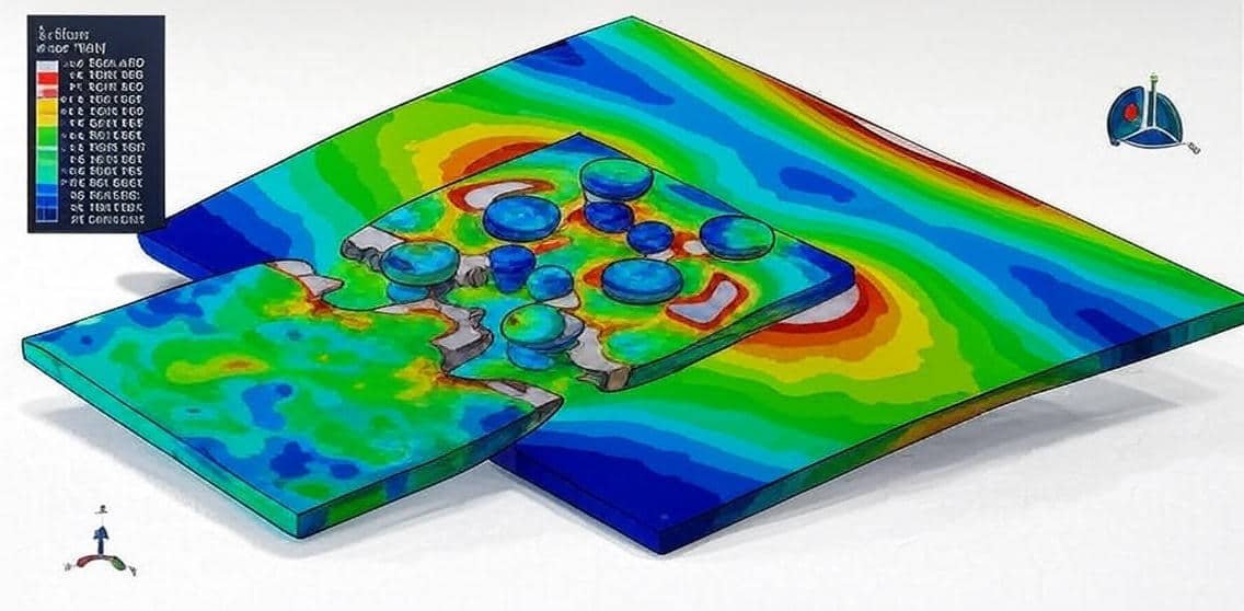
  • Model load distribution across multiple bolts.
  • Study gasket or flange behavior (sealing performance).
  • Capture nonlinear effects like friction, contact, and plastic deformation.
  • Evaluate loosening under vibration.
  • Predict fatigue life.

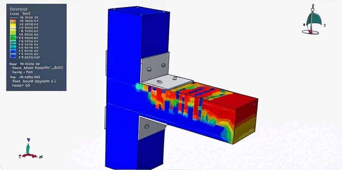
3. Steps in Bolt Simulation (using FEA tools like ANSYS, Abaqus, Nastran, etc.)

  1. Geometry & Meshing
    • Represent bolts explicitly (3D solid model) or with simplified bolt connector elements.
    • Define contact surfaces (threaded regions, bolt head/nut bearing areas).
  2. Preload Application
    • Apply bolt tightening using pretension elements, temperature methods, or displacement constraints.
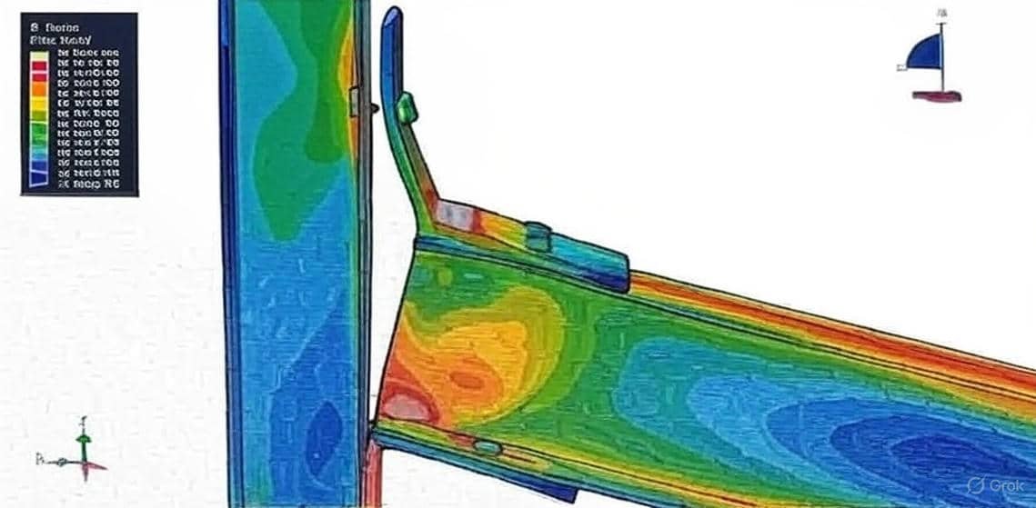
  3. External Loading
    • Apply service loads: tensile, shear, bending, or dynamic loads.
  4. Analysis Types
    • Linear static: Basic stress distribution.
    • Nonlinear static: Includes friction, contact, and plasticity.
    • Fatigue/dynamic analysis: To study vibration and loosening.
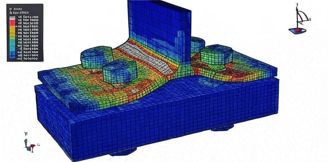
  5. Post-Processing
    • Check bolt stress vs. allowable stress.
    • Evaluate joint separation, slip, or overstress.
    • Assess fatigue safety factor.

4. Common Considerations in Bolt Analysis

  • Torque vs. preload scatter (due to friction uncertainty).
  • Load distribution (not all bolts share the load equally).
  • Joint relaxation (creep, embedment, or gasket compression).
  • Failure modes: Tensile breakage, shear failure, thread stripping, fatigue, and self-loosening.

5. Applications

  • Automotive (engine assembly, chassis joints).
  • Aerospace (critical fasteners in wings, fuselage).
  • Pressure vessels and pipelines (flange/gasket analysis).
  • Heavy machinery and civil structures (steel connections, cranes, wind turbines).

In summary:
Bolt analysis ensures joints remain safe and reliable under preload and service conditions, while simulation (FEA) provides deeper insight into stress, deformation, and fatigue behavior. Together, they form a powerful approach to designing robust bolted connections.

Course Content

Example-1: Analysis of the bolts used as shear connectors in a concrete-filled steel column
In this lesson, the analysis of the bolts used as shear connectors in a concrete-filled steel column in Abaqus through a comprehensive tutorial is studied. In concrete-filled steel tube (CFST) columns, shear connectors are crucial for ensuring composite action between the steel tube and the enclosed concrete core. Bolts are increasingly used as shear connectors due to their ease of installation, adjustability, and effectiveness in transferring shear forces. In this example, the bolts, concrete, and steel column are modeled as three-dimensional solid parts. Bolts offer a practical and efficient solution for shear connection in CFST columns, particularly where welding is impractical. Proper design ensures optimal composite behavior, enhancing the column’s strength and durability.

  • Abaqus Files
  • Document
  • Tutorial Video
    29:21

Example-2: Modeling of steel beam-to-CFST column connection with bolt
In this section, the simulation and modeling of a steel beam-to-CFST column connection with bolts is investigated. Concrete-Filled Double-Skin Steel Tubular (CFDST) columns consist of two concentric steel tubes with concrete sandwiched between them. These columns offer high strength, ductility, and excellent seismic performance. When connecting a steel beam to a CFDST column using bolts, the modeling approach must account for Load transfer mechanisms (axial, shear, moment) Bolt behavior (pre-tension, slip, bearing, shear failure) Concrete-steel interaction (confinement, local buckling) Connection detailing (end-plate, angle cleats, or T-stubs) All parts, such as bolts, steel beams, steel columns, and concrete, are modeled as three-dimensional solids. Modeling steel beam-to-CFDST column bolted connections requires a balance between accuracy and computational efficiency. A mix of detailed FEM and analytical methods ensures reliable predictions for design and assessment.

Example-3: Simulation of the wood-steel plate connection with a bolt under tension load
In this case, the simulation of the wood-steel plate connection with a bolt under tension load in Abaqus is done. A wood-steel plate connection with bolts is a common structural joint used in timber construction to transfer loads between wooden members and steel plates. This type of connection is widely used in beams, columns, trusses, and hybrid structures due to its strength, durability, and ease of assembly. Failure Modes to Check * Wood Splitting (due to insufficient edge distance) * Bolt Shear Failure (if bolts are undersized) * Bearing Failure in Wood (crushing around bolt holes) * Steel Plate Yielding/Buckling (if too thin) *Bolt Withdrawal (if tension forces are present) The important thing in the simulation is the material model of the wood; it can be an elastic-plastic model with damage behavior. After the simulation.

Example-4: Analysis of the behavior of bolted shear connectors in composite slabs with steel deck
In this lesson, the analysis of the behavior of bolted shear connectors in composite slabs with steel deck is investigated. The steel beam, concrete, and bolts are modeled as a three-dimensional solid part. The steel deck is modeled as a shell part. To model steel behavior under large deformation, Johnson-Cook hardening and damage are selected. The concrete damaged plasticity is a good material model for concrete. Over the past few years, more concerns related to the building environments have been greatly addressed to enhance the current building environment and empower future generations to benefit from an ideal life and adequate resources to meet their needs. These concerns include sustainability, energy conservation, construction materials, building deconstruction systems, and recycling/reusing building materials. As far as we know, construction significantly affects the living environment, in particular, the management and demolition of building structures after their intended design service life. The steel-concrete composite structures are widely used nowadays in bridges and high-rise buildings. For achieving the composite action between the composite concrete slabs and steel beams, the welded shear connectors are used in many composite systems due to their shear loading resistance. Consequently, such welded shear connectors make it almost impossible to dismantle, alternate, and deconstruct the composite structures after their design service life.

Example-5: Simulation of the UHPC beam-column joint reinforced with steel angle and bolts
In this section, the simulation of the UHPC beam-column joint reinforced with steel angle and bolts in Abaqus is done. The Ulta-High-Performance-Concrete beam-column joint is modeled as a three-dimensional solid part. The steel bar and strips are modeled as three-dimensional wire parts. The steel angle, plates, and bolts are modeled as three-dimensional solid parts. To model the UHPC joint under normal and axial loading, the Concrete Damage Plasticity is selected. The concrete damage plasticity material model represents a constitutive model that is based on a combination of the theory of plasticity and the theory of damage mechanics. This material model is often used in solving geotechnical problems due to its realistic description of the mechanical behavior of concrete material. To model steel behavior for all metal members, the elastic-plastic behavior with damage properties is considered. Reinforced concrete (RC) moment-resisting frame structures are the most common building type worldwide, including Bangladesh. A huge amount of concrete is produced each year worldwide, and the demand for concrete is increasing. The constituents of concrete are available in several variations, especially for coarse aggregates With the increasing demand for RC construction, the safety of such structures from seismic or dynamic load events is becoming more critical for the civil engineering community

Example-6: Cyclic behavior modeling of the exposed base plates with extended anchor bolts
In this lesson, the cyclic behavior modeling of the exposed base plates with extended anchor bolts in the Abaqus software through a practical tutorial is studied. Cyclic behavior modeling of the exposed base plates with extended anchor bolts. To do the cyclic loading, both general static and dynamic implicit steps can be used. In this example, a general static step with some changes in the convergence model is considered. Abaqus provides many material models for concrete and steel materials under all loading and situations. The Concrete Damage Plasticity material model for the concrete foundation and the proper hardening model in the cyclic loading for the steel members are selected.

Example-7: Fire analysis of a steel joint with bolt connectors
In this case, the fire analysis of a steel joint with bolt connectors in Abaqus is investigated. The two steel plates are modeled as three-dimensional solid parts. The bolts are modeled as three-dimensional parts. The elastic-plastic material data depends on the temperature selected for both heat transfer and static analysis. First, the heat transfer model uses conduction and convection as the fire load is applied and the nodal temperatures are extracted. In the second model, the static analysis with bolt load as the pre-load is applied to the bolts, and the fire results from the previous model are considered as the initial state of the model. Steel has been at the forefront of efficient construction in the last few years, where it has been used widely in the construction of high-rise buildings, industrial structures, and residential structures. What makes steel one of the most appealing materials in the construction industry is its engineering properties. The most appealing properties of steel are its strength-to-weight ratio, ductility, and flexibility. Such properties allow designers to build structures such as skyscrapers, which certainly would have not been possible with any other material. Steel can also be prefabricated and shipped to construction sites easily, which is quite beneficial when it comes to meeting the ever-increasing demands of new buildings. Nevertheless, there is a huge downside to using steel as a construction material because of its low resistance to fire when compared to other construction materials such as concrete. Steel loses almost half of its strength when subjected to temperatures that are equal to or greater than 590 °C, which will eventually lead the structure to fail. The losses that follow structural failures caused by fire are colossal and can take different forms, such as loss of human lives, environmental loss, and economic loss. Hence, the insurance of structural stability of a building under fire loading has been one of the most important and challenging aspects when it comes to designing a new structure. It is important that in the event of a fire, structures can withstand the minimum level of life safety not only for the occupants but also for firefighters and the public that are in proximity to the building. The minimum level of fire safety design must ensure a reduction of the risk of deaths and injuries, protect the contents of a building, and ensure that the building continues to function after the fire with the least amount.

Example-8: Analysis of the steel bolted double angle connections under dynamic load
In this lesson, the analysis of the steel bolted double-angle connections under dynamic load in Abaqus is studied. The beam and column are modeled as three-dimensional solid parts. The bolts are modeled as a three-dimensional solid part. Connections have a crucial role in maintaining the overall stability of steel structures by providing continuity of load paths between structural elements. The steel grade fourteen with elastic-plastic material model is used for all parts. To predict damage and failure in the bolts and beam, ductile damage criterion is considered. In this way the damage can be observe after the simulation. The dynamic explicit step is appropriate for this type of analysis. The mass scale technique to reduce simulation time and make stability in the model is used. The surface to surface contact with contact property to define all contact are implanted. The rough property is considered for the bolts connections.

Example-9: Dynamic bolt failure modeling(bolt and steel plate joint)
In this section, the dynamic bolt failure modeling(bolt and steel plate joint) is done. The upper and bottom steel plates are modeled as three-dimensional solid parts. The bolts are modeled as three-dimensional solid parts. Two main mechanisms can cause the fracture of a ductile metal: ductile fracture due to the nucleation, growth, and coalescence of voids; and shear fracture due to shear band localization. Based on phenomenological observations, these two mechanisms call for different forms of the criteria for the onset of damage. The ductile criterion is a phenomenological model for predicting the onset of damage due to nucleation, growth, and coalescence of voids. The shear criterion is a phenomenological model for predicting the onset of damage due to shear band localization. To observe the failure and damage, those criteria were used. The dynamic explicit step with a mass-scale technique is used to model the dynamic failure of the bolts. The surface-to-surface interaction with interaction properties like friction is considered.

Example-10: Simulation of the dynamic failure behavior of steel beam-to-column bolted connections
In this lesson, the simulation of the dynamic failure behavior of steel beam-to-column bolted connections in Abaqus is studied. Stainless steel displays numerous desirable properties, which motivated many researchers to investigate its use in structural applications. Despite having a comparatively high initial cost, its excellent corrosion resistance, outstanding durability, superior response to elevated temperatures, considerable adaptability, ease of maintenance, and attractive appearance can enable it to be a more effective alternative to carbon steel. Most of the studies in the area of stainless steel structures concentrated on the structural performance of separate members, while the response of stainless steel connections (especially beam-to-column ones) still has not been well-researched. All parts, steel beam, column, steel angle, and bolt, are modeled as three-dimensional solid parts. The steel material with elastic-plastic behavior is used for all parts. To observe damage and failure, especially at the bolt contact zone, the ductile damage criterion is considered. The dynamic explicit step with a mass-scale technique is used. The mass scale option can make stability on the model stable and reduce the time of the simulation. Among all parts, the surface-to-surface interaction with contact property is applied. The surface-to-surface contact offered by ABAQUS was employed for simulating the interactions between the non-welded parts of connections. “Hard” contact relationship was used for the normal interaction, to permit the complete transfer of compression forces and prohibit the tensile stresses from being transmitted across the interface.

Example-11: Analysis of the composite plate connection with a steel bolt under tension load
In this section, the analysis of the composite plate connection with a steel bolt under tension load in Abaqus is done through a step-by-step tutorial. The two composite plates are modeled as three-dimensional solid parts. The steel bolt is modeled as a three-dimensional solid part. Because of the symmetry, half of the model is used to reduce the simulation time. Steel material with elastic-plastic behavior is used for the bolt. The ductile damage criterion to predict damage and failure of the bolt under tension load is implied. To model a composite material, epoxy-glass is used. The lamina elastic type with failure stress is selected. To predict damage in the composite layers, Hashin’s damage criterion with damage evolution is considered. The continuum shell section with four layers is selected for the two composite parts. The dynamic explicit procedure is selected to model the dynamic tension on the plates.

Example-12: Modeling of the shear failure of two steel plates with bolt connections
In this case, the modeling of the shear failure of two steel plates with bolt connections in Abaqus is studied. The steel plates are modeled as a three-dimensional solid part. The bolts with different sizes are modeled as a three-dimensional solid part. The steel material with elastic-plastic behavior is used. The ductile and shear damage criterion to predict the damaged zone and failure is used. The ductile criterion is a phenomenological model for predicting the onset of damage due to nucleation, growth, and coalescence of voids. The shear criterion is a phenomenological model for predicting the onset of damage due to shear band localization. The dynamic explicit step was used to model the dynamic load as tension at the end of the upper plate. The surface-to-surface contact with the contact property is used among all interaction domains.

Example-13: Bolt failure in the bolted joint
In this lesson, the bolt failure in the bolted joint is studied. The two steel plates and the bolt are modeled as a three-dimensional solid part. To obtain failure, the ductile damage criterion is used for all parts. The steel material with elastic-plastic behavior is implied. By using the ductile criterion, Abaqus can predict the damage zone and failure area under the tension load. This analysis can be done with two static and dynamic procedures. In this tutorial static procedure is used as a general static step. To avoid early non-convergence, some changes are applied in the static step. The surface-to-surface contact with the contact property is assigned to the contact domain. The symmetry boundary is assigned to the side surfaces of the plate.

Example-14: Analysis of the steel beam-column connection with bolt-failure model
In this case, the analysis of the steel beam-column connection with the bolt-failure model is considered. The beam with endplate is modeled as a three-dimensional solid part, the column is modeled as a three-dimensional solid part, and the ten bolts are modeled as three-dimensional solid parts. The steel material for the bolt is modeled as elastic-plastic behavior that depends on the strain rate, ductile damage with evolution, and shear damage with evolution to predict damage and failure in the bolt. The steel material for the column and for the beam is modeled as elastic-plastic with a ductile damage criterion. The dynamic explicit procedure is used to model large deformation and failure analysis in this simulation. All interactions, like a bolt with a beam or a bolt with columns, are assumed as the surface-to-surface contact with contact property behavior as a friction coefficient and normal contact.

Example-15: Bolt failure simulation on the steel beam and column connection
In this lesson, the bolt failure simulation on the steel beam and column connection is investigated. The bolts, steel beam, and column are modeled as three-dimensional parts. The steel structure is an assemblage of different members, such as beams, columns, and plates, which need to be fastened or connected. The basic goal of connection design is to produce a joint that is safe, economical, and simple. It is also important to standardize the connections in a structure and to detail it in such a way that it allows sufficient clearance and adjustment to accommodate any lack of fit, resists corrosion, is easy to maintain, and provides a reasonable appearance. Because of the bolt or column failure, the steel is modeled as an elastic-plastic material with ductile and shear damage criteria to observe damage and failure on the parts. The dynamic explicit step is appropriate for this type of analysis because of the large deformation that can’t be done with standard analysis with the static solver. The surface-to-surface interaction among all parts is considered. The friction coefficient and hard contact property are assigned as the contact property.

Example-16: Analysis of the exposed column base plate connections in moment frames
In this section, the analysis of the exposed column base plate connections in moment frames is done. The steel column, bolts, steel bed plate, and concrete foundation are modeled as three-dimensional solid parts. To model concrete foundations, both normal and UHPC are used to make a compression between two materials as a strength approach. The elastic-plastic model coupled with damage behavior is used for all steel members. In this example, both static and dynamic ways can be used; because of the large deformation and failure, the dynamic method is better. In low and mid-rise steel structures in the seismic regions of the United States and elsewhere, exposed-type column base plate connections are commonly used to transfer axial forces, shears, and moments from the entire structure into the foundation. Finite element simulations are ideal for providing insight into stress distributions and deformation modes that inform the development of engineering models for characterizing connection strength. The FE simulations utilized in this study are highly sophisticated, featuring large deformations and an accurate simulation of the components and phenomena such as contact and multi-axial constitutive responses of the steel, concrete, and grout.

Example-17: Simulation of the dynamic compression test of a steel column with the UHPC core in interaction with a concrete foundation
In this lesson, the simulation of the dynamic compression test of a steel column with the UHPC core in interaction with a concrete foundation in ABAQUS is studied. The concrete foundation and column are modeled as three-dimensional solid parts. The steel column and steel stiffener angles are modeled as shell parts. The steel bed and bolts are modeled as three-dimensional solid parts. The steel reinforcements are modeled as the wire parts. To model normal and Ultra-High-Performance-Concrete, the Concrete Damaged Plasticity model is selected. The model is a continuum, plasticity-based, damage model for concrete. It assumes that the two main failure mechanisms are tensile cracking and compressive crushing of the concrete material. Slump is a test to measure the plasticity of concrete. The slump test is the most commonly used method of measuring the consistency of concrete, which can be employed either in the laboratory or at the site of work. It is not a suitable method for very wet or very dry concrete. For all steel parts in the simulation, the elastic-plastic model and damage behavior are selected. The steel reinforcements are embedded inside the concrete foundation. The dynamic explicit step and static general can be used.

Reviews

No Review Yet
No Review Yet
199,00 425,00
22 people watching this product now!

Material Includes

  • 1- Abaqus Files
  • 2- Document
  • 3- Tutorial Videos

Audience

  • 1- Mechanical Engineering
  • 2- Civil Engineering
  • 3- Structural Engineering
  • 4- Manufacturing Engineering

Related  Products

See more

Want to receive push notifications for all major on-site activities?