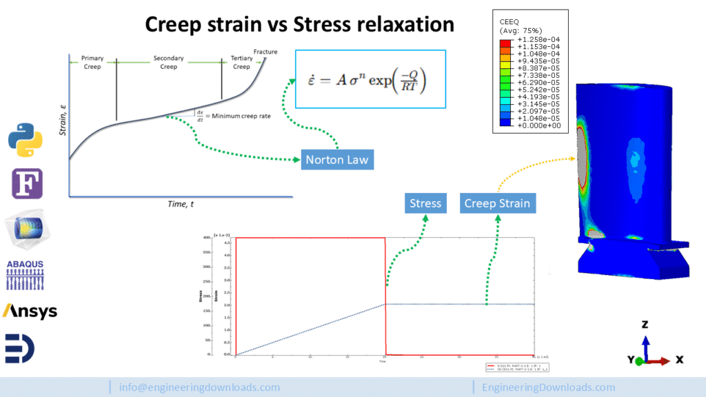
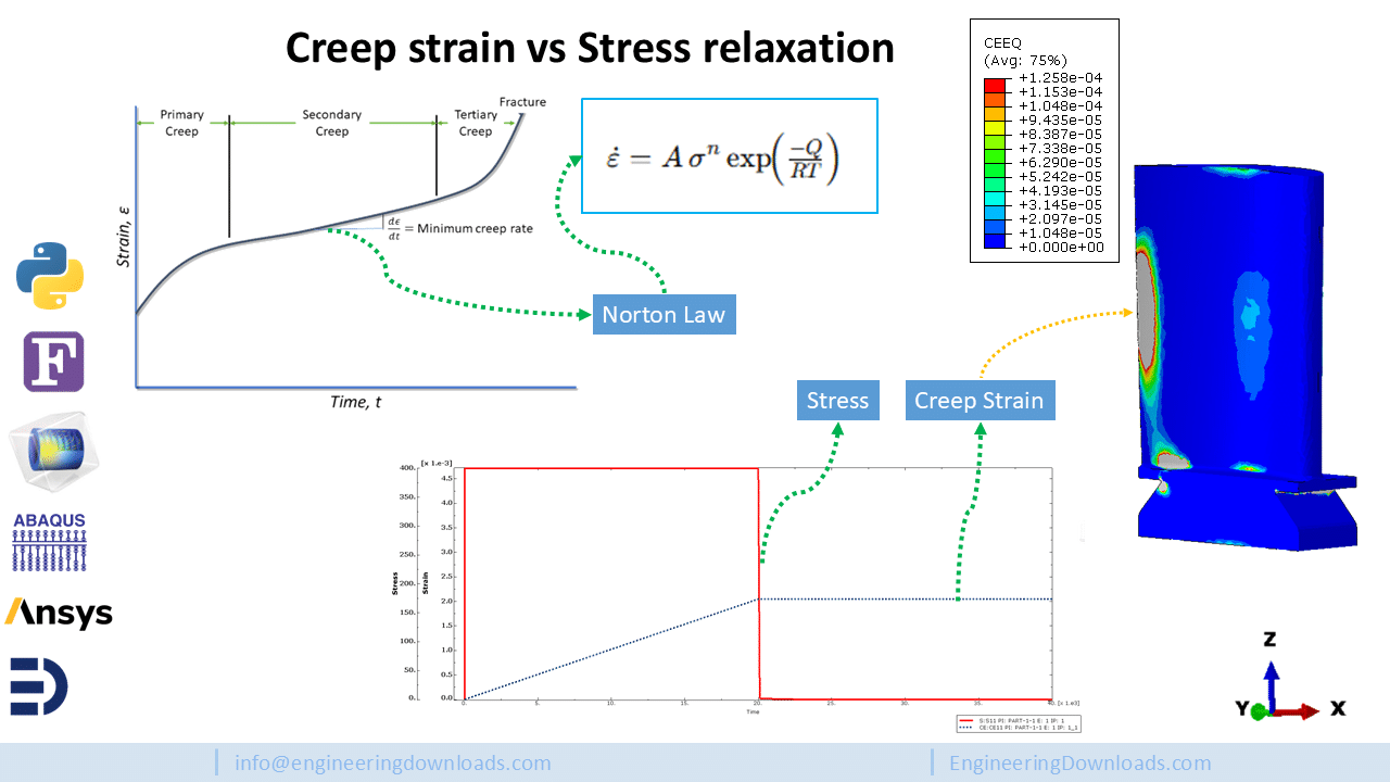
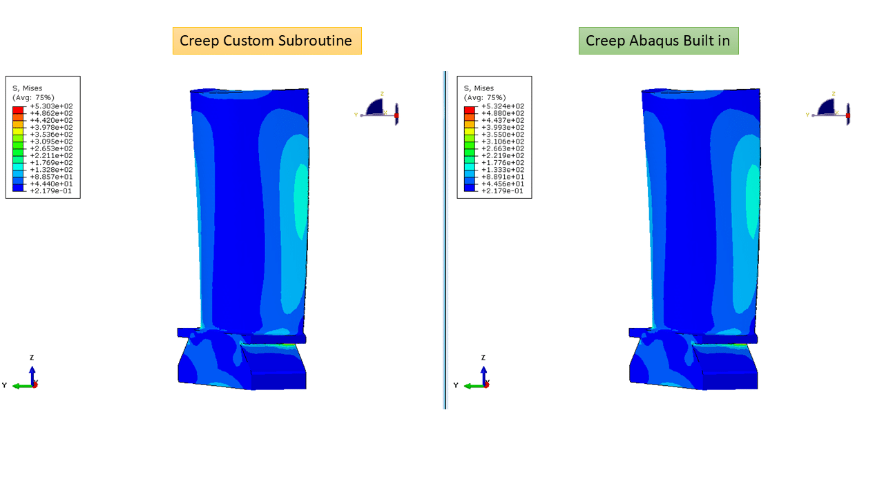
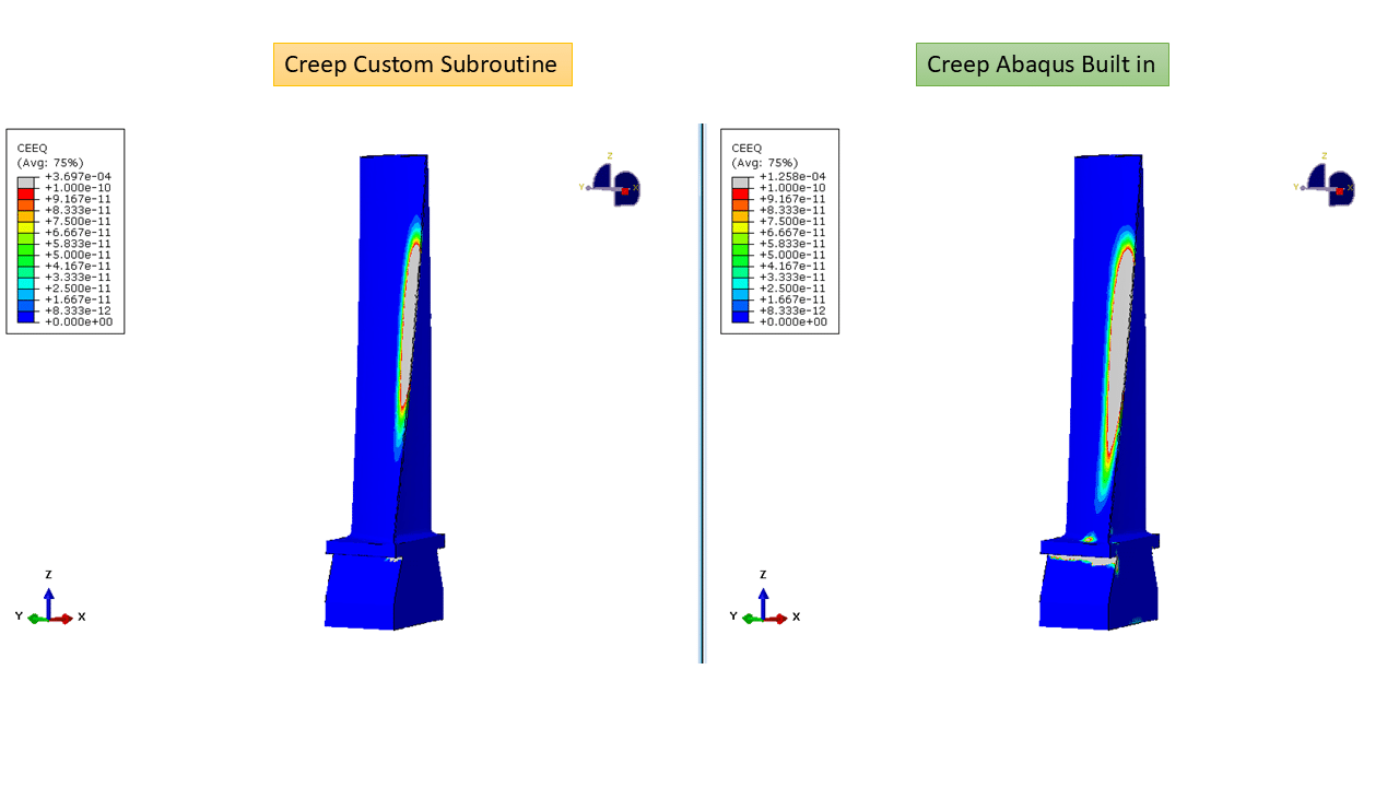
This CAE demonstration shows a single blade model where you can directly compare a built-in strain-hardening creep material and a custom CREEP subroutine in the same simulation workflow, focusing on blade creep behavior. The study follows a two-step workflow (thermal → creep) and delivers full thermo-mechanical outputs so engineers can evaluate differences in distribution, deformation, and life-prediction metrics.
Workflow
What you get (results & outputs)
About the Author
Saman Hosseini – is a structural engineer who’s helped many researchers and engineers in academic and industrial projects to solve complex simulations. You can visit his Engineering Downloads profile here.

Abaqus
€81,00 €39,00

Abaqus
€299,00 €249,00

Uncategorized
€95,00 €80,00
Abaqus
€79,00 €38,00
Abaqus
€68,00 €34,00
Abaqus
€77,00 €39,00
Abaqus
€79,00 €39,00
See more

Want to receive push notifications for all major on-site activities?