Engineering Downloads

Let’s Learn and Collaborate

Engineering Downloads

Biomechanics Package

189,00 359,00
189,00 359,00
16 people watching this product now!

Material Includes

  • 1- Tutorial videos
  • 2- Abaqus files
  • 3- Related References

Audience

  • 1- Biomedical Engineering
  • 2- Mechanical Engineering

What You Will Learn?

  • This course is designed for students and professionals in biomedical and mechanical engineering, as well as those in dentistry and orthopedics who want to understand the mechanics behind biological tissues and medical devices. Learners will develop the ability to analyze how fluids and bones respond to forces, explore fracture and implant mechanics, and apply engineering simulations to solve real-world clinical and design challenges. By the end, participants will have a clear grasp of how biomechanics informs innovations in surgery, dental systems, and implant technology.

About Course

Biomechanics package

This course provides a comprehensive exploration of biomechanics applied to orthopedic and dental contexts, with a focus on the mechanical principles that govern biological tissues and medical devices. Students will engage with a series of practical, simulation-based examples that bridge theoretical concepts with real-world applications in clinical engineering.

The curriculum is structured to progressively build understanding, starting with fundamental flow and material models before advancing to bone mechanics and implantology. Key topics include:

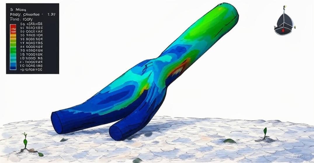
  • Fluid and Tissue Mechanics: Understanding non-Newtonian models such as Newtonian blood flow and transport phenomena.

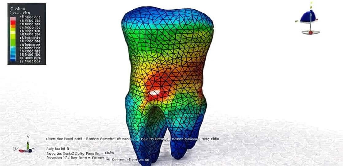
  • Bone Mechanics and Failure: Analyzing bone structure under cutting, drilling, and cracking scenarios to study mechanical resistance and fracture patterns.

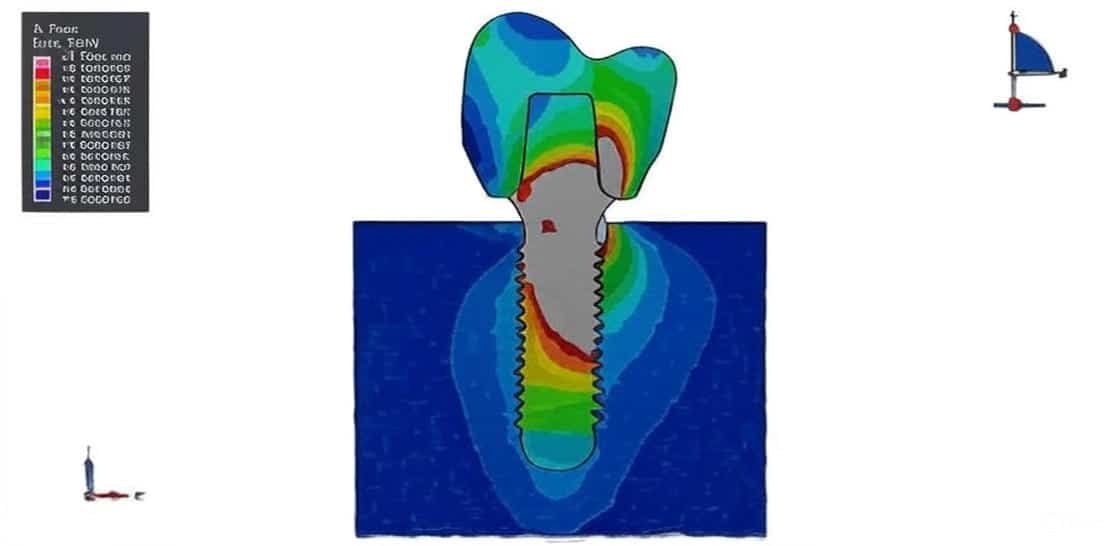
  • Dental and Orthopedic Applications: Investigating implant insertion, pull-out forces, and static loading on teeth and bone.

  • Advanced Implant Design: Evaluating porous structures such as TiFoam implants and their interaction with bone for optimized fixation and osseointegration.

Through these modules, students will gain the ability to simulate, analyze, and interpret biomechanical systems, strengthening their understanding of the interface between engineering design and biological function. The course emphasizes practical problem-solving skills and prepares learners to contribute to innovation in medical devices, surgical planning, and clinical biomechanics research.

Course Content

Example 1: Fluid Structure Interaction simulation of human blood with the coronary vessel
In this lesson, the analysis of the Fluid Structure Interaction simulation of human blood with the coronary vessel is studied. In this tutorial Fluid Structure Interaction simulation of human blood with a coronary vessel in Abaqus has been investigated. Cardiovascular diseases represent the most frequent cause of death in modern civilization. In particular, these represent 49% of deaths in Europe and 38% in the United States. The common index for these pathologies, known as CVD (cardiovascular disease), includes various types of cardiovascular diseases and is considered one of the most important references for global human health. A very important class is coronary disease, which is included in the category of cardiovascular diseases with the index CAD (coronary artery disease). In this class, the most significant role is played by atherosclerotic diseases, which are caused by the formation, development, and rupture of atherosclerotic plaques. In this tutorial, blood and vessel geometry are imported as a three-dimensional part. CFD analysis was first done in Abaqus CFD, and then the result was imported into the standard analysis in Abaqus Standard. The blood is assumed to be a fluid with density and viscosity. After CFD analysis, the velocity and pressure …can be achieved, and after the standard analysis of the vessel, the stress and displacement are obvious. The Co simulation engine in the tutorial has been implied.

  • Abaqus files
  • Video
    00:00
  • Documents

Example 2: FSI simulation of the blood and vessel
In this section, the FSI simulation of the blood and vessel is investigated. In this tutorial FSI simulation of blood and vessels in the Abaqus-Co Simulation process has been studied. Hemodynamic factors, including pressure, flow rate, and shear stress, have been shown to play an important role in vascular diseases, such as atherosclerosis and aneurysms. Recent advances in medical imaging techniques, such as magnetic resonance imaging (MRI) and computed tomography (CT), can provide exquisite anatomical information about the vasculature. Based on computational fluid dynamics (CFD), blood flow simulation provides a unique way to quantify hemodynamics in high spatial and temporal resolution. While initially, blood flow simulations were performed using idealized geometric models, in the last decade, the majority of papers report results using image-based, subject-specific models. Abaqus CFD was used to simulate blood flow stream by using flow step and inlet, outlet boundary conditions. The boundary is assigned to the vessel part in the standard module. The mesh should be the same in the two analyses, and the quality of the mesh has a good effect on the result. After the simulation, stress and displacement for the vessel, which comes from the CFD analysis, and pressure and velocity in the blood flow, which comes from the vessel effect, can be achieved.

Example 3: Analysis of the non-Newtonian blood flow behavior
In this case, the analysis of the non-Newtonian blood flow behavior is done through a comprehensive tutorial. The blood solid part can be created in Abaqus, or it can be imported as a CAD part to the Abaqus CFD. The default model for the blood in Abaqus CFD is the Newtonian model, and to create a non-Newtonian model, the Carreau-Yasuda viscosity model is selected. This model has been successful in representing the shear-thinning behavior of blood. Blood is a complex biological fluid and has elements in its composition, such as erythrocytes, which give it a non-Newtonian behavior. Typically, when carotid blood flow is studied, this aspect is frequently ignored, and blood is modeled as a Newtonian fluid, with constant viscosity. The Carreau-Yasuda model is not available in Abaqus cae, and it needs some modification in the edit keyboard file. The flow step with laminar for the flow type regime is selected. The inlet boundary condition, as the inlet velocity, is assigned to the entrance zone. Two outlet boundaries as a pressure condition as selected for the two outlet zones. Wall boundary condition is also assigned to the outer surfaces, and shear wall outputs are requested for them.

Example 4: Simulation of the femur bone fracture under rigid impact
In this lesson, the simulation of the femur bone fracture under rigid impact is studied. Impactor was modeled as a rigid body with an initial velocity to penetrate into the femur bone. To create bone geometry, we used SolidWorks, and then the bone was imported to ABAQUS. To predict fracture area in bone JC material model has been used. This model provided plasticity with a damage model properly for the impact process. To define a general contact that considers an internal element, edit keyboard capability has been implemented.

Example 5: Numerical modeling of the orthogonal cutting of cortical bone
In this section, the numerical modeling of the orthogonal cutting of cortical bone is done using the CEL method. Cutting of bone is a common operation in orthopedic traumatologic surgery and dentistry. Cutting operations in bones involve a wide range of operations, including grinding, sawing, or drilling, see for instance. It is well known in the field of manufacturing that the importance of proper definition of machining operations for process efficiency (including both time and cost) and surface integrity. This concept is translatable to bone cutting since it is required to conjugate low cutting time (in order to diminish the total time of the surgery) and surface quality (mainly related to thermal bone damage) because the thermally affected layer at the machined bone could involve osteonecrosis. The use of validated modeling tools, such as the finite element method (FE), could help in the analysis and definition of machining operations in bones. However, one of the most important factors in the achievement of accurate simulations is the statement of proper constitutive equations representative of bone behavior. To model this simulation Eulerian approach has been used. The Johnson-Cook material model is used as the material model for bone. A dynamic temp explicit step is appropriate for this type of analysis.

Example 6: Analysis of the bone drilling process
In this case, the analysis of the bone drilling process is done. The drilling of bone is ubiquitous in many fields of surgery, including orthopaedics, neurosurgery, plastics and reconstructive, craniomaxillofacial, and ear, nose, and throat. A cylindrical tunnel is typically prepared in bone using a surgical drill-bit to accommodate a screw or other threaded device for rigid fixation, which is provided by the integration of bone (cancellous and/or cortical) with the screw threads. In this configuration, bone screws are resistant to axial and shear forces as well as bending moments and therefore suited to the load-bearing function of the skeleton during locomotion. Drill bits are also used in the preparation of bony tunnels, such as in anterior cruciate ligament reconstruction. A dynamic explicit procedure is appropriate for this type of analysis. General contact with considering internal damage and erosion, is used as an input file. The rotation velocity with axial displacement is applied to the drill, and during the simulation, the drill penetrates the bone and creates a hole inside it.

Example 7: Analysis of the bone crack growth under bending load
In this lesson, the analysis of the bone crack growth under bending load is studied. Structural analysis of bones is now actively studied by many researchers using the finite-element method (FEM) to better understand the mechanism of bone fractures. Most previous studies, however, only obtained distribution patterns of stress or strain, and did not show how a fracture initiates and proceeds or how a fracture line grows. There are several different ways in which a bone can fracture; for example, a break to the bone that does not damage surrounding tissue or tear through the skin is known as a closed fracture. On the other hand, one that damages the surrounding skin and penetrates the skin is known as a compound fracture or an open fracture. Compound fractures are generally more serious than simple fractures because, by definition, they are infected The bone is modeled as a two-dimensional part with an elastic material coupled with a traction separation law to define crack growth during the simulation. Static analysis and XFEM procedure are appropriate for this type of analysis.

Example 8: Simulation of the dental implant in interaction with the mandible bone
In this section, the simulation of the dental implant in interaction with the mandible bone is investigated. The crown, Abutment, and mandible bone are modeled as three-dimensional parts. Dental implants are metal posts or frames that are surgically positioned into the jawbone beneath your gums. Once in place, they allow your dentist to mount replacement teeth onto them. Because implants fuse to your jawbone, they provide stable support for artificial teeth. Dentures and bridges mounted to implants won’t slip or shift in your mouth an especially important when eating and speaking. This secure fit helps the dentures and bridges, as well as individual crowns placed over implants, feel more natural than conventional bridges or dentures. The ceramic material with elastic-plastic behavior and ductile damage criterion is used for the crown. The titanium material with elastic-plastic material and Johnson-Cook damage is used to model root or abutment material. The mandible bone is modeled as an elastic-plastic material. The dynamic explicit procedure is appropriate for the dynamic loading conditions. The general contact algorithm with contact property is used to model all contacts among the parts. The proper boundary condition is assigned to the mandible, and a concentrated force with smooth amplitude is selected for the crown. The mesh should be fine because of the complexity of the model.

Example 9: Modeling of the pull-out process of medical screw from the bone
In this case, the modeling of the pull-out process of a medical screw from the bone is done. This type of threaded fastener is primarily screwed into the bone without any tension in the screw or clamping force in the bone. Applications include neck and spine injuries, as well as hip and knee replacements. The strength of the screw connection is one of the main concerns in the post-surgery recovery and the long-term mobility of the patient. Hence, it is important that a high reliability level is ensured for those self-tapping screws used in medical devices. The bone is modeled as a three-dimensional solid part. The screw is imported to the Abaqus because of its complex geometry as a rigid part. The Johnson-Cook hardening law is frequently applied to analyze the dynamic behavior of metal alloys. This hardening law is generally pre-implemented in FE codes, including ABAQUS/Explicit. To model bone behavior under dynamic load, the elastic and Johnson-Cook plasticity is used. To consider the damage parameter, the Johnson-Cook damage criterion is used. The contact zone between the bone and the screw has experienced damage and failure under dynamic pull-out. The dynamic explicit step is appropriate for this type of analysis. The mass scale technique reduces the time of the simulation. To consider failure and erosion on the contact zone, the general contact capability, which considers the erosion as an input file, is implied.

Example 10: Analysis of the human tooth under static load
In this lesson, the analysis of the human tooth under static load is studied. Due to the universal character of the finite element method, which enables modeling of complex physical phenomena, its increasingly broad use in an interdisciplinary context, connected with the analysis of mechanical parameters of modern materials, can be observed. Among the present-day areas of application of numerical analyses involving FEM, bioengineering, and dentistry can be included, with respect to the assessment of stress levels and qualification of strength hypotheses in bone tissues. It allows designing and optimizing modern materials used for dental reconstructions, such as crowns or crown-root fillings, as well as assessing the risk of unsuccessful dental treatment resulting in damage to the hard dental tissue structure or the filling material. Numerical simulations using the finite element method in dentistry can constitute a stage of preclinical tests connected with bio-mechanical aspects of the design and optimization of dental fillings. The Abaqus doesn’t have this capability to create a complex geometry such as a tooth, skull, and …so the tooth part is imported to the Abaqus as a SAT part.

Example 11: Simulation of the titanium foam behavior for dental applications
In this case, the simulation of the titanium foam behavior for dental applications is done. In this tutorial, the finite element simulation of titanium foam behavior as an implant under dynamic load in Abaqus has been investigated. metal foams, new class materials, have increasingly been employed for a range of applications such as structural components, automotive parts, sound and vibration absorbers, heat exchangers, and biomedical implants. This is due to their unique combination of properties such as low density, high specific stiffness, high specific strength, and good energy absorption capability. Among metal foams, titanium foams (Ti-foams) are preferred in many crucial applications, including biomedical implants where biocompatibility is required. The main interests in using cellular metals come from the increase in the friction coefficient between the implant and the surrounding bone. It allows mechanical interlocking of bone with the implant by substantial bone ingrowth and better long-term stability. Additionally, the stiffness of the implants can be tailored by varying porosity to reduce the stress shielding effect

Example 12: Modeling of the dental implant insertion
In this lesson, the modeling of the dental implant insertion is studied. Successful osseointegration is a degree of implant stability that occurs after implant integration. This result is related to two terms, namely primary and secondary implant stability. Primary stability characterizes the mechanical engagement of the implant right after its insertion, while secondary stability is the result of (longer-term) bone regeneration and remodeling (biological process) around the inserted implant. Primary and secondary stability are closely related, as poor primary stability is one of the major causes of implant failure. The finite element method (FEM) is a widely used stress analysis method for the investigation of the biomechanical behavior of bone implant-rehabilitation components, and simulation/evaluation of their mechanical interaction, which is otherwise extremely difficult to investigate experimentally, either in vitro or in vivo. The FEM enables researchers to apply different loading configurations and determine the displacement and the stress levels experienced by the tooth, prosthesis, implant, and bone. The implanted root is modeled as a three-dimensional part that is imported to Abaqus because of its complexity. The implant is assumed as a rigid body. The mandible bone is modeled as a three-dimensional solid part.

Example-13: Pull-out test analysis of a ceramic nail from the bone
In this section, the pull-out test analysis of a ceramic nail from the bone is investigated. The ceramic nail or screw is a three-dimensional solid part. The bone is modeled as a three-dimensional solid part. Because of the part’s difficulties, they are imported into the Abaqus. Cortical screws are intended for dense cortical bone, but cancellous screws are for less dense cancellous bone. Cortical screws feature a lower thread depth and a more aggressive pitch, allowing them to engage well in cortical bone. Ceramic is a slow-heating material that can be perfect for users who dab at low temperatures. It retains the heat for longer, too. So there’s no need to frequently reheat the nail. To model ceramic behavior, the material combination of the elastic, equation of state, Drucker-Prager hardening, and ductile damage criterion has been used. This combination can represent the brittle behavior of the ceramic nail. The Johnson-Cook damage and hardening are also used to model bone behavior under dynamic load. The dynamic explicit step is appropriate for this type of analysis. The mass scale technique is also considered to reduce the time of simulation and make the model a quasi-static one. Two types of interaction are selected in this model, first, the friction behavior and perfect contact as the second type. At the end of the simulation. The proper boundary conditions and meshes are assigned to the two parts.

Example-14: Arrowhead’s impact on the human skull
In this case, the arrowhead’s impact on the human skull is done. The Bronze Age (approximately 3300–1200 BCE, varying by region) marked a transformative period in human history, characterized by the widespread use of bronze for tools, weapons, and armor. As societies became more complex and conflicts more frequent, warfare and interpersonal violence became prominent aspects of Bronze Age life. Archaeological and osteological evidence sheds light on how weapons were used in combat and the kinds of injuries they inflicted.Among the most common weapons of the time were daggers, swords, spears, clubs, and arrows. The development and use of these tools significantly altered patterns of violence, leaving telltale signs on human remains—particularly trauma to the skull, a frequent target in combat. Case Studies & Archaeological Evidence: In various European and Near Eastern Bronze Age burial sites, skulls have been found with bronze arrowheads lodged in them, providing direct evidence of fatal arrow strikes. A well-known case is from Jebel Sahaba (Nubia, though earlier than the Bronze Age), where multiple skeletons were found with projectile points embedded in bones, suggesting organized violence or warfare. In Central Europe, Late Bronze Age conflict sites such as Tollense Valley (Germany) have revealed numerous skeletons with cranial trauma likely caused by arrowheads and blunt weapons—pointing to large-scale battles.

Reviews

Student Ratings & Reviews

No Review Yet
No Review Yet
189,00 359,00
16 people watching this product now!

Material Includes

  • 1- Tutorial videos
  • 2- Abaqus files
  • 3- Related References

Audience

  • 1- Biomedical Engineering
  • 2- Mechanical Engineering

Related  Products

See more

Want to receive push notifications for all major on-site activities?