Engineering Downloads

Let’s Learn and Collaborate

Engineering Downloads

Beam-Column Joint Analysis and Simulation Package

278,00 517,00
278,00 517,00
15 people watching this product now!

Material Includes

  • 1- Abaqus Files
  • 2- Documents
  • 3- Tutorial Videos

Audience

  • 1- Civil Engineering
  • 2- Structural Engineering
  • 3- Mechanical Engineering

What You Will Learn?

  • This package includes 23 detailed tutorials that comprehensively cover the modeling and analysis of steel and concrete beam-column joints in Abaqus. It describes various types of joints, including steel-to-steel, concrete-to-concrete, and steel-to-concrete connections, as well as open-leg column and wide beam-column configurations.
  • The tutorials address a wide range of loading conditions, such as seismic and cyclic loading, axial load, and compression. In addition, different joint types and strengthening components are discussed, including bolted connections, welded steel angles, gusset plates, stiffeners, FRP, ECC, and more.
  • This package is designed to help you master the modeling and simulation of beam-column joints in Abaqus, providing both theoretical understanding and practical guidance.

About Course

Introduction to Beam Column Joint Simulation and Analysis

Beam column joints are critical regions in framed structures where beams and columns intersect, transferring loads and moments between the vertical and horizontal members. The structural performance of these joints significantly influences the overall stability, ductility, and energy dissipation capacity of a building, especially under lateral loads such as wind or earthquakes. Consequently, accurate simulation and analysis of beam-column joints are essential for understanding their behavior and ensuring structural safety.

This package includes 23 detailed tutorials that comprehensively cover the modeling and analysis of steel and concrete beam-column joints in Abaqus. It describes various types of joints, including steel-to-steel, concrete-to-concrete, and steel-to-concrete connections, as well as open-leg columns and wide beam-column configurations. The tutorials address a wide range of loading conditions, such as seismic and cyclic loading, axial load, and compression. In addition, different joint types and strengthening components are discussed, including bolted connections, welded steel angles, gusset plates, stiffeners, FRP, ECC, and more.

1. Importance of Beam-Column Joints

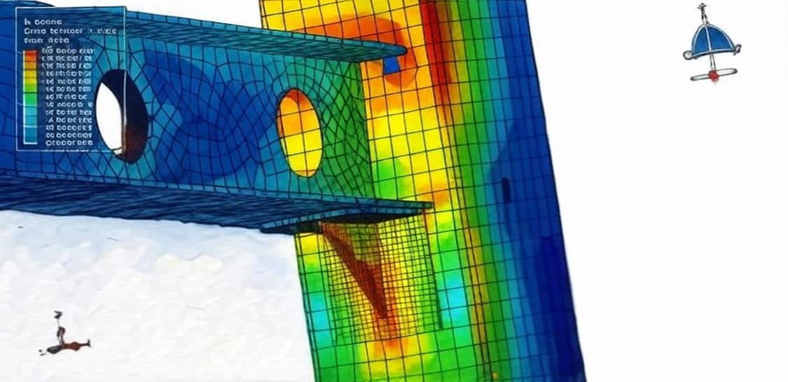
In both steel and reinforced concrete (RC) structures, the joint region experiences complex stress states due to the interaction of axial, shear, and bending forces. Failure or excessive deformation of these joints can lead to progressive collapse of the entire frame system. Therefore, their design and analysis require detailed consideration of material behavior, load transfer mechanisms, and connection detailing.

2. Steel Beam-Column Joints

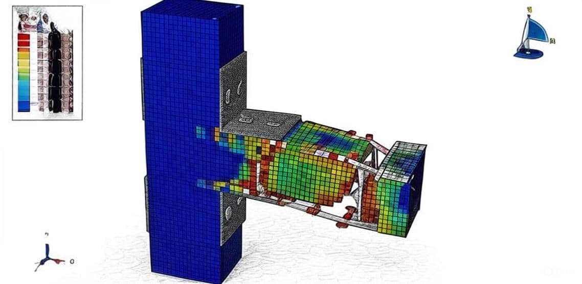
In steel structures, beam-column joints are typically formed using bolted or welded connections. These joints are designed to provide sufficient stiffness and strength while accommodating deformation.
Key factors influencing the performance of steel joints include:

  • Connection type (moment-resisting, semi-rigid, or shear connection)
  • Bolt pretension and slip behavior
  • Weld strength and residual stresses
  • Plate thickness and geometry

Finite Element Analysis (FEA) tools such as Abaqus are widely used to model these connections, capturing non-linear material behavior, contact interactions, and potential failure modes like bolt shear or plate yielding.

3. Reinforced Concrete Beam-Column Joints

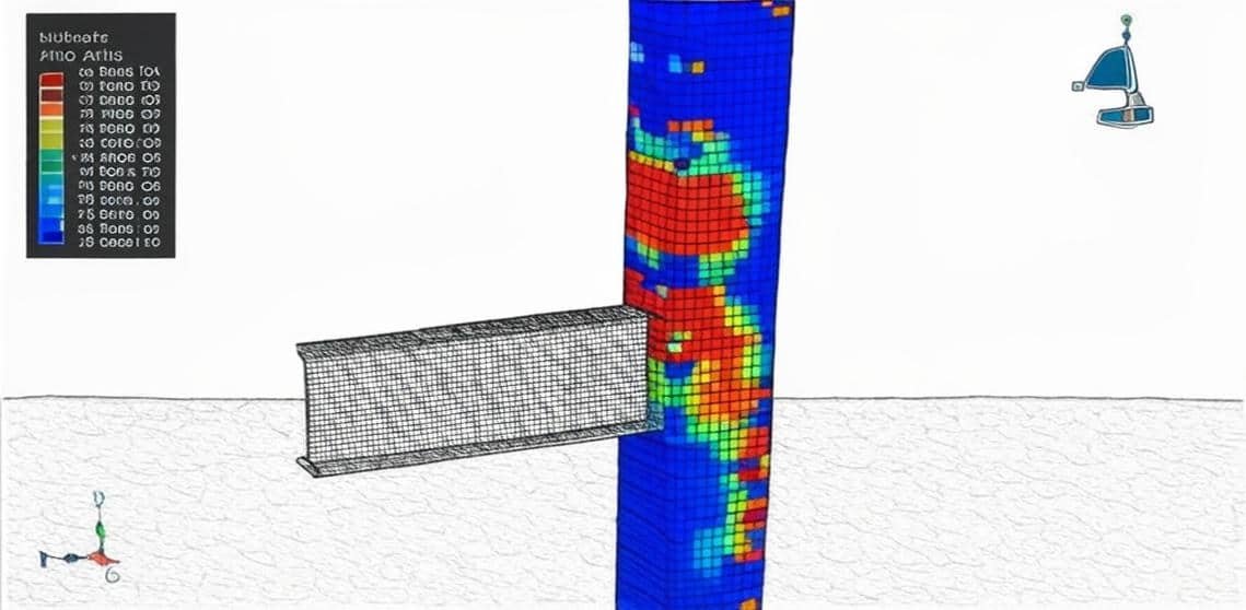
In reinforced concrete frames, joints are monolithic regions where reinforcement from beams and columns intersect. Under seismic or cyclic loading, these joints are often the most vulnerable zones due to stress concentration and bond deterioration between concrete and steel.
Important aspects include:

  • Anchorage and bond-slip behavior of reinforcement
  • Concrete cracking and crushing
  • Confinement effects from transverse reinforcement
  • Shear strength and joint core degradation

Nonlinear analysis in Abaqus can simulate these effects using material models such as the Concrete Damaged Plasticity (CDP) model, rebar embedded constraints, and contact definitions between steel and concrete.

4. Simulation and Analysis Using Abaqus

Abaqus provides an advanced environment for modeling both steel and concrete beam-column joints through:

  • Material nonlinearity: capturing yielding, cracking, and damage
  • Geometric nonlinearity: large deformation and contact effects
  • Dynamic analysis: for seismic or impact loading conditions
  • Meshing and boundary conditions: refined mesh in joint regions to capture stress concentration

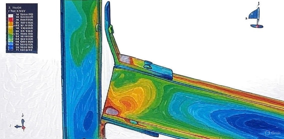
Parametric studies can be conducted to evaluate the effects of geometry, reinforcement ratio, connection detailing, and loading conditions on joint behavior. Results typically include stress distribution, load-displacement response, and potential failure mechanisms.

5. Applications

  • Seismic performance evaluation of RC frames
  • Strength and stiffness assessment of steel moment connections
  • Retrofit design and detailing improvements
  • Code validation and performance-based design research

Course Content

Example-1: Analysis of the steel beam-open leg column joints under cyclic loading
In this lesson, the analysis of the steel beam-open leg column joints under cyclic loading is studied. Steel structure columns are vertical members in a steel structure that support the load-bearing beams and other structural elements above. They are typically made of high-strength steel and come in various shapes and sizes to meet the specific needs of the building or structure. The steel beam and column are modeled as three-dimensional parts, all the stiffener plates are modeled as three-dimensional parts. The steel column is the structural component that bears the main vertical load in the steel structure building. Based on their cross-sectional shape, they are classified into solid-web and lattice columns. The solid web column has an overall cross-section, with commonly used shapes being I-beams, typically made of hot-rolled H-beams, I-beams, or welded H-beams. Solid web columns are generally used in light steel structure buildings. The proper material model is used for all members to consider the cyclic loading effect. The general static step is appropriate for this type of analysis. In each cycle, a specific load is applied to the steel beam by using a certain displacement through an amplitude.

  • Abaqus Files
  • Document
  • Tutorial Video
    00:00

Example-2: Modeling of the UHPC beam-column joint reinforced with steel angle and bolts
In this section, the modeling of the UHPC beam-column joint reinforced with steel angle and bolts is investigated. The Ulta-High-Performance-Concrete beam-column joint is modeled as a three-dimensional solid part. The steel bar and strips are modeled as three-dimensional wire parts. The steel angle, plates, and bolts are modeled as three-dimensional solid parts. Reinforced concrete (RC) moment-resisting frame structures are the most common building type worldwide, including Bangladesh. A huge amount of concrete is produced each year worldwide, and the demand for concrete is increasing. The constituents of concrete are available in several variations, especially for coarse aggregates With the increasing demand for RC construction, the safety of such structures from seismic or dynamic load events is becoming more critical for the civil engineering community. To model the UHPC joint under normal and axial loading, the Concrete Damage Plasticity is selected. The concrete damage plasticity material model represents a constitutive model that is based on a combination of the theory of plasticity and the theory of damage mechanics. This material model is often used in solving geotechnical problems due to its realistic description of the mechanical behavior of concrete material. To model steel behavior for all metal members, the elastic-plastic behavior with damage properties is considered.

Example-3: Load bearing capacity analysis of a composite joint between a reinforced concrete column and a steel beam
In this case, the load bearing capacity analysis of a composite joint between a reinforced concrete column and a steel beam is presented. The concrete column is modeled as a three-dimensional solid part. The steel beam and column are modeled as three-dimensional solid parts. The steel bar and strip are modeled as wire parts. The reinforced concrete column and steel beam (RCS) frames consist of reinforced concrete (RC) columns and steel (S) beams. This type of structure has several advantages over traditional RC frames or steel frames, including lower cost and structure weight reduction. RC columns offer, superior damping properties to a structure, especially in tall buildings. Indeed, using RC instead of structural steel as columns can result in substantial savings in material cost and an increase in the structural damping and lateral stiffness of the building. The energy dissipation capacity can accordingly be provided through steel beams. In addition, steel floor systems are significantly lighter compared to RC floor systems, leading to substantial reductions in the weight of the building, foundation costs, and inertial forces. To actively apply RCS frames in a real structure, it is necessary to study the composite connection between steel beams and reinforced concrete columns. Extensive studies have been conducted to study the basic force transfer mechanisms in connection regions and the performance of various joint configurations that enhance the connection performance under seismic excitations. The American Society of Civil Engineers. To model concrete behavior under axial or cyclic loading, the Concrete damaged plasticity is selected. The Concrete damage plasticity material model represents a constitutive model that is based on a combination of the theory of plasticity and the theory of damage mechanics. This material model is often used in solving geotechnical problems due to its realistic description of the mechanical behavior of concrete material. The elastic-plastic model with damage behavior is considered for the steel members. Dynamic explicit or General static steps both are useable. The proper interactions and constraints are applied to the model. The load as displacement with a smooth amplitude is considered.

Example-4: Cyclic loading simulation of a steel beam-column joint with welded steel angle and stiffeners
In this lesson, the cyclic loading simulation of a steel beam-column joint with welded steel angles and stiffeners is studied. The box column, steel beam angles, and stiffeners are modeled as three-dimensional solid parts.When a structural steel member is subjected to a cyclically varying load of sufficient amplitude, it may fail after a certain number of load repetitions, even though the maximum load in a single cycle is much lower than that required to cause yielding or fracture. Cyclic loading refers to the process in which stress or strain is repeatedly applied to a material over time, causing alternating periods of loading and unloading. It is a key factor in the study of material fatigue and failure.Under cyclic loading, the elastic deformation is recovered during unloading, while the irreversible deformation remains. The irreversible deformation, its growth trend, and the accumulation of total fatigue are directly related to fatigue damage.To model steel material under cyclic loading, kinematic or combined hardening models can be used to represent the stress–strain behavior in each cycle. The analysis procedure follows a general static approach. To define the weld joints, surface-to-surface interactions or constraints can be used. Proper boundary conditions with the cyclic loading protocol are applied to the beam, and a fine mesh is required to obtain accurate results.After the simulation, results such as stress, strain, displacement, hysteresis diagrams, plastic strain, and other parameters are available for analysis.

Example-5: Cyclic loading analysis of a steel beam-column joint filled with the UHPC and welded stiffeners
In this section, the cyclic loading analysis of a steel beam-column joint filled with UHPC and welded stiffeners is investigated. The Ultra-High-Performance Concrete (UHPC) is modeled as a three-dimensional solid part. The steel beam and column are modeled as three-dimensional shell parts, while the stiffeners are modeled as three-dimensional solid parts.To model the UHPC material, the Concrete Damage Plasticity (CDP) model is used. This model is a continuum, plasticity-based damage model for concrete. It assumes that the two primary failure mechanisms are tensile cracking and compressive crushing of the concrete material. Tension and compression data, along with damage parameters, are used as input for this model.To represent the steel behavior, two models are applied: (1) elastic–isotropic plasticity with ductile damage, and (2) the combined hardening model. In the ductile damage model, two main mechanisms can cause the fracture of a ductile metal: ductile fracture due to the nucleation, growth, and coalescence of voids; and shear fracture due to shear band localization. Based on phenomenological observations, these two mechanisms require different criteria for the onset of damage. In the combined hardening model, the yield surface evolves during the analysis.Both static and dynamic procedures can be used. A welded contact or perfect contact condition is assumed among all surfaces, and general contact with friction behavior is also considered. Appropriate boundary conditions, loads, and mesh refinement are applied to ensure accurate results.

Example-6: Seismic behavior of RC exterior wide beam-column joints
In this case, the seismic behavior of reinforced concrete (RC) exterior wide beam-column joints is analyzed. The concrete beam and column are modeled as three-dimensional solid parts, while the steel bars and strips are modeled as three-dimensional wire parts.Reinforced concrete structures with wide and shallow beams offer several advantages from both constructional and architectural perspectives. A wide beam system can reduce the amount of formwork through repetition, thereby significantly lowering construction costs and simplifying the construction process. Furthermore, a smaller story height can be achieved in wide beam systems due to the shallower beam depths.The Concrete Damage Plasticity (CDP) model is used to define the beam-column behavior under cyclic loading. This model is a continuum, plasticity-based damage model for concrete. It assumes that the two primary failure mechanisms are tensile cracking and compressive crushing of the concrete material.Elastic–plastic material properties are assigned to the steel reinforcements. A general static analysis step, with modifications to the convergence model, is used. The steel reinforcements are embedded within the concrete beam-column system.

Example-7: Analysis of the RC beam-column joint reinforced with steel plates and rods under vertical load
In this lesson, the analysis of an RC beam-column joint reinforced with steel plates and rods under vertical loading is presented. The concrete beam-column is modeled as a three-dimensional solid part. The steel bars and strips are modeled as three-dimensional wire parts, while the steel plates and rods are modeled as three-dimensional solid parts. Concrete is a highly heterogeneous material that exhibits complex nonlinear mechanical behavior. Moreover, defining damage in a concrete structure is a challenging task. In the finite element analysis of concrete structures, appropriate material models are used to capture this behavior. One such model is the Concrete Damage Plasticity (CDP) model, which combines the yield theory of plasticity and the theory of damage mechanics to simulate the behavior of concrete structures effectively. In this example, the material parameter identification for the CDP model is carried out. The CDP model is capable of representing both tensile and compressive damage in the beam-column joint after loading. For all steel reinforcements, elastic–plastic material behavior is assumed. To model the damage behavior of the steel plates and rods, the ductile damage criterion is employed. Both static and dynamic analysis steps can be used in this tutorial; however, to reduce the simulation time, a dynamic explicit step with the mass scaling technique is adopted. Perfect contact, surface-to-surface contact with friction, and embedded region constraints are applied between the interacting parts.

Example-8: Modeling behavior of beam-bolumn joints strengthened with UHPFRC under axial load
In this section, the modeling behavior of beam-bolumn joints strengthened with UHPFRC under axial load is investigated. The concrete beam-column is modeled as a three-dimensional solid part. The steel bar and strip are modeled as three-dimensional wire part. The steel plates and rods are modeed as three-dimensional solid part. Concrete is a very heterogeneous material which shows complex nonlinear mechanical behavior. In addition, it is very difficult to define damage in a concrete structure. In the analysis of concrete structures using the finite element method, material models are used for these purposes. An example of these material models is concrete damage plasticity material model. This material model combines the yield theory of plasticity and theory of damage mechanics to analyze the concrete structures behavior effectively. Material parameters identification of concrete damage plasticity material model is performed in this example. The concrete damaged plasticity can shows the tension and compression damage of the beam column joint after loading. The steel material with elastic-plastic behaviour is considered for all steel reinforcement. To model damage behaviour of the steel plates and rods, the ductile damage criterion is selected. Both dynamic and static step can be used in this tutorial, to decrease the time of the simulation, dynamic explicit step with mass scale technique is used. The perfect conctact, surface to surface contact with friction, and embdded region constraint are applied for all parts. The concentrated force is applied to the top surface of the column and displacement to the end of the beam.

Example-9: Analysis of the Ultra-High-Performance Concrete (UHPC) beam-column joint under cyclic loading
In this case, the analysis of an Ultra-High-Performance Concrete (UHPC) beam-column joint under cyclic loading is presented. The UHPC beam-column joint is modeled as a three-dimensional solid part, while the steel bars and strips are modeled as three-dimensional wire parts. Ultra-High-Performance Concrete (UHPC) is an advanced material in the concrete industry, known for its superior characteristics such as high compressive and tensile strength, ductility, and durability. The UHPC material data are used to model the beam-column behavior under cyclic loading. The Concrete Damage Plasticity (CDP) model requires separate input data for compression and tension. For the steel bars and strips, an elastic–plastic material model is applied. To simulate cyclic loading, a general analysis step with modifications to the convergence model is used, and the appropriate output variables are requested to obtain the hysteresis diagram during visualization. The embedded region constraint is applied to the bars and strips embedded within the concrete host. Fixed boundary conditions are assigned to the top and bottom surfaces of the column, while cyclic displacement is applied to the free end of the beam according to the defined loading protocol.

Example-10: Modeling of the dynamic failure behavior of a steel beam-to-column bolted connection
In this lesson, the modeling of the dynamic failure behavior of a steel beam-to-column bolted connection is studied. Stainless steel exhibits numerous desirable properties that have motivated many researchers to explore its use in structural applications. Despite its comparatively high initial cost, its excellent corrosion resistance, outstanding durability, superior performance at elevated temperatures, considerable adaptability, ease of maintenance, and attractive appearance make it a potentially more effective alternative to carbon steel. Most studies in the field of stainless steel structures have focused on the structural performance of individual members, while the behavior of stainless steel connections—particularly beam-to-column connections—has not yet been thoroughly investigated. All components, including the steel beam, column, steel angle, and bolts, are modeled as three-dimensional solid parts. An elastic–plastic material model is used for all steel components. To capture damage and failure, particularly in the bolt contact zones, the ductile damage criterion is employed. A dynamic explicit step with a mass scaling technique is used to enhance numerical stability and reduce simulation time. Surface-to-surface interactions with appropriate contact properties are defined between all mating parts. The surface-to-surface contact algorithm provided by ABAQUS is employed to simulate the interactions between non-welded components of the connection. A hard contact relationship is used for the normal interaction, allowing the full transfer of compressive forces while preventing the transmission of tensile stresses across the interface. Fixed boundary conditions are applied to both ends of the column, and the load is applied at the free end of the steel beam.

Example-11: Analysis of the concrete beam-column joint under cyclic loading
In this section, the analysis of a concrete beam-column joint under cyclic loading is presented. The concrete beam-column joint is modeled as a three-dimensional solid part, while the strips and bars are modeled as three-dimensional wire parts. An elastic–plastic material model is used for the steel strips and bars. The Concrete Damage Plasticity (CDP) model is employed to account for the tensile and compressive damage of the concrete part during cyclic loading. This model is a continuum, plasticity-based damage model for concrete. It assumes that the two primary failure mechanisms are tensile cracking and compressive crushing of the material. The uniaxial tensile and compressive responses of concrete are represented within the damaged plasticity framework. The objective of this simulation is to obtain the damage parameters for the concrete part. A general static step is used, which is appropriate for this type of analysis. The embedded region constraint is applied to define the strips and bars embedded within the concrete host. Fixed boundary conditions are assigned to both ends of the column, while cyclic displacement with amplitude control is applied at the beam ends to implement the loading protocol.

Example-12: Cyclic loading of the steel beam-column structure
In this case, the cyclic loading of the steel beam-column structure is done. The beam is modeled as a three-dimensional shell part, and two steel columns are modeled as three-dimensional shell parts. To model steel beams and columns under cyclic loading, elastic-isotropic plasticity coupled with a ductile damage criterion to predict damage during the simulation is used. The kinematic or combined plasticity can be used, but to predict damage, the isotropic plasticity and ductile damage can provide a better result. The general static step is appropriate for this type of analysis, and to avoid early non-convergence, some changes are made in the convergence model. The perfect or ideal contact is used between the beam and the columns. The general contact algorithm is selected to consider some regions that have interference during the simulation. The fixed boundary condition is assigned to the bottom nodes of the column. The displacement boundary with the cyclic protocol as amplitude is implied for the columns.

Example-13: Modeling of ECC/Concrete Composite Beam-Column Joint under axial load
In this lesson, the modeling of ECC/Concrete Composite Beam-Column Joint under axial load is studied. For conventional reinforced concrete frame structures, the seismic performance mostly depends on the deformation ability of key components such as beams, columns, and their joint zones. Under earthquake actions, these members are expected to maintain substantial inelastic deformations without a significant loss of load-carrying capacity. Among these structural components, beam-column joints are designed to sustain vertical live or dead loads transferred from beams and slabs, horizontal loads from earthquake actions and wind, leading to complicated stresses in the joint zone. In recent years, a class of high-performance fiber-reinforced cementitious composites (called engineered cementitious composites (ECC) with ultra-ductility has been developed for applications in the construction industry. Substitution of conventional concrete with ECC strategically in concrete frame structures may provide a method to solve the deficiencies resulting from the brittleness of concrete. ECC and concrete have a similar range of tensile and compressive strengths, while they have distinct differences in tensile deformation behavior. For conventional concrete, it fails in a brittle manner once its tensile strength is reached. However, for an ECC plate under uniaxial tension, after first cracking, tensile load capacity continues to increase with strain hardening behavior accompanied by multiple cracks along with the plate. The Column and concrete beam are modeled as one solid part. The strips and bars are modeled as three-dimensional wire parts. The Concrete Damaged Plasticity is used to model the concrete behavior. The data were extracted from the reference paper. The steel material with elastic-plastic behavior for strips and bars is used. The general static step is appropriate for this type of analysis. The surface-to-surface contact algorithm with contact property is implied between the rigid plate and the concrete beam. The bars and strips are embedded inside the concrete host.

Example-14: Cyclic loading analysis of a steel beam-column structure reinforced with CFRP
In this section, the cyclic loading analysis of a steel beam-column structure reinforced with CFRP is investigated. The steel beam and column are modeled as a three-dimensional shell part. The CFRP plates are modeled as a planar shell part. To model steel behavior under cyclic loading, the combined plasticity was used. This material model can predict the behavior of the material at each cycle. To define CFRP material, engineering constants, and elasticity with Hashin’s damage criterion was used. The general static step with some changes in the convergence model has been implied. The perfect or ideal contact between the steel beam and steel column, steel beam, and CFRP sheets is used. The fixed boundary condition is used at the top and bottom ends of the steel column, and displacement with an amplitude as a loading protocol is assigned to the end of the steel beam. The fine mesh has a good effect on the results.

Example-15: Cyclic loading modeling of a steel beam-column with a steel angle and gusset
In this case, the cyclic loading modeling of a steel beam-column with a steel angle and gusset is presented. The steel beam and box column are modeled as a three-dimensional shell part. The steel angle and gusset are modeled as a three-dimensional solid part. For all parts, steel material with elastic-plastic behavior and ductile damage criterion to predict the damaged zone is used. The cyclic loading causes failure and damage, especially at the joint zone, and that damage criterion can be considered in a good way. The general static step with a specific time period is selected. The contact between the steel angle and the beam, the steel angle and the column, is assumed as a perfect contact, like a weld joint. The fixed boundary condition is assigned to the top and bottom edges of the column, and a displacement with an amplitude as a protocol is assigned to the beam.

Example-16: Cyclic loading analysis of the reduced beam section-column with stiffener
In this study, the cyclic loading analysis of the reduced beam section-column with stiffener is studied. The RBS part is modeled as a three-dimensional shell part, the box column, and the stiffener is modeled as three-dimensional shell parts. The reduced beam section (RBS) connection, commonly known as the dogbone connection, is a widely adopted moment-resisting connection configuration used to improve the seismic performance of steel frame structures. In this design, a portion of the beam flange near the column face is intentionally reduced to form a plastic hinge away from the welds, thereby controlling the location of yielding and minimizing the risk of brittle fracture at the beam-to-column interface.Under cyclic loading, which simulates the effects of earthquake-induced lateral forces, the RBS connection is subjected to repeated loading and unloading cycles that cause material yielding, stiffness degradation, and potential strength deterioration. The cyclic performance of such connections depends on several factors, including the geometry of the reduced section, the material properties, the weld configuration, and the presence of stiffeners.The inclusion of stiffeners in the column web or beam flange region enhances local stability, delays buckling, and improves energy dissipation capacity under cyclic loading. Stiffeners also contribute to the redistribution of stresses around the reduced section, allowing the connection to sustain higher inelastic deformations without significant loss of strength.In this analysis, a detailed finite element model is developed to investigate the cyclic behavior of the RBS beam-to-column connection with stiffeners. The model captures nonlinear material behavior, large deformations, and contact interactions to accurately simulate the cyclic response. The main objectives are to evaluate the stress distribution, plastic hinge formation, hysteresis behavior, and failure mechanisms of the connection, providing insights into its performance and potential for seismic-resistant design.

Example-17: Modeling of the concrete beam-column joint under axial load
In this section, the modeling of the concrete beam-column joint under axial load is investigated. Strengthening of existing reinforced concrete structures is now a major part of the construction activity all over the world. The RCC structures constructed across the world are often found to exhibit distress and suffer damage, even before service life is over, due to several causes such as earthquakes, corrosion, overloading, change of codal provisions, improper design, faulty construction, explosions, and fire. With the mandate to go vertical, in light of the rising population and space crunch, most of the structures that have come up over the last three or more decades are all framed structures. For all framed structures, the most important component is the beam-column joint, and the structural design of the joint is usually neglected. During the design stage, attention is only restricted to the provision of sufficient anchorage for the beam. Unsafe design and detailing within the joint region are dangerous for the entire structure, even though the structural members themselves may conform to the design requirements. It is well known that joint regions in reinforced concrete framed structures are recognized as very critical as they transfer the forces and bending moments between the beams and columns.

Example-18: Analysis of a steel beam-column connection with bolt and failure modeling
In this case, the analysis of a steel beam-column connection with bolt and failure modeling is presented. The beam with endplate is modeled as a three-dimensional solid part, the column is modeled as a three-dimensional solid part, and the ten bolts are modeled as three-dimensional solid parts. Steel beam-to-column connections are critical components in moment-resisting frames, as they directly influence the structural integrity, ductility, and overall seismic performance of steel structures. Bolted connections are widely used due to their ease of installation, reliability, and ability to accommodate prefabricated elements. However, under severe or cyclic loading, these connections may experience complex stress states leading to local yielding, bolt slippage, fracture, or overall connection failure. The analysis of steel beam-column connections with bolts requires a detailed understanding of both material and geometric nonlinearities. Steel exhibits elastic–plastic behavior, while bolts may undergo ductile deformation and, in some cases, fracture. Accurate modeling of these behaviors is essential to predict the progressive failure mechanisms, including bolt yielding, shear failure, local flange or web buckling, and the redistribution of forces in the connection. Finite element modeling is an effective tool to simulate the response of bolted steel connections. By incorporating material nonlinearities, contact interactions, and appropriate boundary conditions, it is possible to capture key behaviors such as bolt slippage, stress concentrations around bolt holes, and progressive damage. Ductile damage criteria or other failure models can be applied to steel components and bolts to simulate fracture and assess the connection’s ultimate capacity. This analysis aims to investigate the structural performance, stress distribution, and failure mechanisms of a steel beam-to-column connection with bolts. The study provides insights into the connection’s load-bearing capacity, ductility, and potential modes of failure, which are essential for designing safe and resilient steel structures. The steel material for the bolt is modeled as elastic-plastic behavior that depends on the strain rate, ductile damage with evolution, and shear damage with evolution to predict damage and failure in the bolt. The steel material for the column and for the beam is modeled as elastic-plastic with a ductile damage criterion. The dynamic explicit procedure is used to model large deformation and failure analysis in this simulation. All interactions, like a bolt with a beam or a bolt with columns, are assumed as the surface-to-surface contact with contact property behavior as a friction coefficient and normal contact.

Example-19: Modeling of the steel beam-column connection with steel angle under cyclic loading
In this lesson, the modeling of the steel beam-column connection with a steel angle under cyclic loading is studied. The beam and column are modeled as three-dimensional shell parts, and the steel angle is modeled as a three-dimensional shell part. Steel beam-to-column connections play a crucial role in the overall behavior and seismic performance of steel frame structures. Among various connection types, connections reinforced with steel angles provide an efficient method to transfer moments and shear forces while enhancing the ductility and stability of the joint. Steel angles are often used as stiffeners or secondary supports at the beam-column interface to improve load distribution and prevent premature local failures.Under cyclic loading, which simulates earthquake or repeated service loads, steel beam-column connections experience alternating stress and strain, leading to stiffness degradation, energy dissipation, and potential local or global failure. Accurately capturing this behavior requires detailed modeling of both material and geometric nonlinearities, as well as the interaction between the beam, column, and reinforcing angles.Finite element modeling allows for a comprehensive investigation of the cyclic response of such connections. The steel components are typically modeled with elastic–plastic material behavior, while the steel angles are included as three-dimensional elements to represent their contribution to stiffness and load transfer. Contact interactions, boundary conditions, and loading protocols are critical to simulate realistic cyclic effects, including stress concentration, local yielding, and potential fracture.The aim of this study is to analyze the structural performance, hysteresis behavior, and failure mechanisms of a steel beam-column connection reinforced with steel angles under cyclic loading. The results provide insights into the effectiveness of steel angles in enhancing joint strength, ductility, and energy dissipation, which are essential for designing resilient steel structures. The steel material is modeled as elastic-plastic with ductile damage parameters to model failure behavior under cyclic loading. The shell thickness should be in the correct direction to avoid interference. The general static step with some modification to avoid not convergence error. The general contact algorithm with contact property as friction and hard contact is used. The contact between the steel angle and the column- steel angle and beam is assumed as perfect contact because they are welded. The fixed boundary conditions for the end of the column and displacement base on the specific protocol are assigned.

Example-20: Bolt failure analysis of the steel beam-column connection under dynamic load
In this section, the bolt failure analysis of the steel beam-column connection under dynamic load is investigated. The bolts, steel beam, and column are modeled as three-dimensional parts. The steel structure is an assemblage of different members, such as beams, columns, and plates, which need to be fastened or connected. The basic goal of connection design is to produce a joint that is safe, economical, and simple. It is also important to standardize the connections in a structure and to detail it in such a way that it allows sufficient clearance and adjustment to accommodate any lack of fit, resists corrosion, is easy to maintain, and provides a reasonable appearance. Steel beam-to-column connections are critical components in moment-resisting frames, as they directly affect the strength, ductility, and overall seismic performance of steel structures. Bolted connections are widely used due to their ease of assembly, reliability, and ability to accommodate prefabricated components. However, under dynamic loading, such as seismic or impact forces, bolts can be subjected to complex stress states, potentially leading to slippage, yielding, or fracture, which may compromise the structural integrity of the connection. Accurately predicting bolt failure under dynamic conditions requires consideration of both material and geometric nonlinearities. Steel bolts exhibit elastic–plastic behavior, and failure may occur due to ductile fracture, shear, or combined stress mechanisms. Understanding the sequence and location of bolt failure is essential for evaluating the progressive collapse of the connection and ensuring the safety of the structure. Finite element modeling provides an effective tool for simulating the dynamic behavior of bolted connections. By incorporating detailed representations of bolts, beams, and column components, and contact interactions, it is possible to capture key phenomena such as stress concentration around bolt holes, bolt yielding, slippage, and fracture initiation. Advanced material models, including ductile damage criteria, can be used to simulate bolt failure and assess the connection’s ultimate load-bearing capacity. The primary objective of this study is to investigate the failure mechanisms, stress distribution, and dynamic response of a steel beam-column connection with bolts. The results offer valuable insights into the performance, resilience, and potential design improvements of bolted steel connections under dynamic loading conditions. Because of the bolt or column failure, the steel is modeled as an elastic-plastic material with ductile and shear damage criteria to observe damage and failure in the parts. The dynamic explicit step is appropriate for this type of analysis because of the large deformation that can’t be done with standard analysis with the static solver. The surface-to-surface interaction among all parts is considered. The friction coefficient and hard contact property are assigned as the contact property. The fixed boundary condition for the end of the column and displacement as a load for the beam is assigned with the smooth step amplitude.

Example-21: Damage mechanism analysis of the beam-column connection under cyclic loading
In this case, the damage mechanism analysis of the beam-column connection under cyclic loading is presented. The beam and column are modeled as a three-dimensional shell part. Beam-column connections are critical elements in steel and reinforced concrete frames, as they govern the load transfer, ductility, and overall seismic performance of structures. Under cyclic loading, such as that induced by earthquakes or repeated service loads, these connections experience alternating stress and strain, which can lead to progressive damage, stiffness degradation, and eventual failure. Understanding the mechanisms of damage is essential for designing connections that are both safe and resilient.The damage in beam-column connections can manifest in various forms, including local yielding of the beam or column, fracture or yielding of bolts, flange or web buckling, and concrete cracking in reinforced concrete joints. The initiation and propagation of these damage mechanisms depend on material properties, connection geometry, reinforcement detailing, and the type of loading applied.Finite element analysis provides a powerful tool to investigate the damage mechanisms in beam-column connections under cyclic loading. By incorporating nonlinear material behavior, contact interactions, and appropriate boundary conditions, the simulation can capture critical phenomena such as plastic hinge formation, stress concentration, fatigue accumulation, and progressive failure. Material models, such as ductile damage for steel or concrete damage plasticity for concrete, allow for accurate prediction of the onset and evolution of damage in the connection components.The aim of this study is to analyze the damage mechanisms, stress distribution, and failure modes of beam-column connections under cyclic loading. The results can provide valuable insights for improving connection design, enhancing ductility, and ensuring structural safety under repeated or seismic loads. Steel material is used for beam and column as elastic elastic-plastic material combined with ductile damage criterion with evolution to predict the damage zone during cyclic loading. A general static step is appropriate for this type of analysis. To avoid unconvergence during the simulation increment time has changed.

Example-22: CFRP jacketed reinforced concrete beam-column joint under axial load
In this lesson, the CFRP jacketed reinforced concrete beam-column joint under axial load is studied. Various types of strengthening materials, such as steel plates, ferrocement, and fiber-reinforced polymer,s, are available in the construction industry to be used for jacketing of the affected components, the most common being steel jackets. These types of jackets increase the weight and dimensions of the structural elements. A few attempts have been made for the use of corrugated or plain steel plates as jacketing material in concrete frames. FRP-based strengthening has become attractive as compared to others due to its light weight, high strength and stiffness, corrosion resistance, easier implementation, excellent fatigue, etc., and is an attractive alternative to restore the joints to their desired capacity. The beam and concrete column are modeled as three-dimensional parts with CDP material behavior, beams are modeled as a wire part with steel material, and CFRP sheets are modeled as a shell part with Hashin’s damage criterion. Reinforced concrete (RC) beam-column joints are critical elements in framed structures, as they govern the load transfer between beams and columns and significantly influence the overall structural performance. Under axial loading, these joints are subjected to high compressive forces, which can lead to concrete crushing, joint shear failure, or reinforcement yielding. Strengthening such joints is essential, especially in retrofitting or upgrading existing structures to meet higher load demands or seismic requirements.Carbon fiber-reinforced polymer (CFRP) jackets have emerged as an effective technique to enhance the axial load capacity and ductility of RC members. CFRP composites provide high tensile strength, excellent corrosion resistance, and minimal added weight, making them suitable for structural strengthening applications. When applied around a beam-column joint, CFRP jackets improve confinement, delay crack propagation, and increase the overall stiffness and load-bearing capacity of the joint.Finite element modeling allows for a detailed investigation of the mechanical behavior of CFRP-strengthened RC joints under axial load, capturing nonlinear material behavior of concrete, steel reinforcement, and CFRP laminates. Material models, such as concrete damage plasticity for concrete and elastic orthotropic behavior for CFRP, enable accurate prediction of stress distribution, failure mechanisms, and the effectiveness of CFRP confinement.The main objective of this study is to analyze the structural performance, load capacity, and failure mechanisms of CFRP-jacketed RC beam-column joints under axial loading. The results provide insights into the benefits of CFRP strengthening and inform design strategies for enhancing the resilience and durability of reinforced concrete structures.

Example-23: Analysis of the Proposed Concrete-Filled Steel Tube Connections under Reversed Cyclic Loading
In this section, the analysis of the proposed concrete-filled steel tube connections under reversed cyclic loading is investigated. Composite steel-concrete structures are used in civil engineering projects worldwide. In recent decades, concrete-filled steel tube (CFT) structures have become accepted and used in buildings because they can provide the enhanced advantages of ductility associated with steel structures and concrete components. The advantages of CFT columns over other steel-concrete composite structures, called either mixed or hybrid systems, include the fact that the inside concrete prevents local buckling of the steel tube wall and that the steel tube extends the ability of concrete spalling. Although the CFT can be an economical form of composite construction, its use has been limited due to the complexity of the beam-to-column connections and the limited construction experience The steel column and beams are modeled as a three-dimensional shell part. The steel material is modeled as an elastic-plastic material with a ductile damage criterion to predict damage initiation and propagation during cyclic loading. The concrete material is modeled as an elastic material with the Concrete Damage Plasticity model to predict tensile damage during the analysis. The combined plastic model can also be used. The general static step with a specific time period is selected. The contact beam and column, and the steel column with concrete, are assumed to be in perfect contact. The fixed boundary condition is assigned to the top and bottom surfaces of the column, and displacement in the reverse direction is assigned to the two beams.

Reviews

No Review Yet
No Review Yet
278,00 517,00
15 people watching this product now!

Material Includes

  • 1- Abaqus Files
  • 2- Documents
  • 3- Tutorial Videos

Audience

  • 1- Civil Engineering
  • 2- Structural Engineering
  • 3- Mechanical Engineering

Related  Products

See more

Want to receive push notifications for all major on-site activities?