Demystifying Pressure Vessel Stress Analysis for Engineers
As engineers, we know that pressure vessels are critical components across countless industries – from oil & gas and chemical processing to power generation and even aerospace. Their safe operation is paramount, and at the heart of ensuring that safety lies robust pressure vessel stress analysis. This isn’t just about crunching numbers; it’s about understanding material behavior, anticipating failure modes, and ultimately, safeguarding lives and assets.

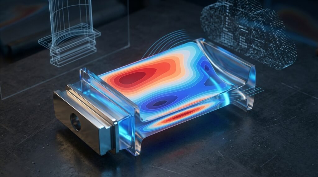
Image: Illustrative FEA stress plot of a pressure vessel showing stress distribution.
This guide aims to provide a clear, practical, engineer-to-engineer walkthrough of pressure vessel stress analysis. We’ll cut through the academic jargon and focus on actionable insights, common pitfalls, and the tools that help us get the job done right.
Why Stress Analysis is Non-Negotiable for Pressure Vessels
The consequences of pressure vessel failure can be catastrophic: explosions, leaks of hazardous materials, environmental damage, and significant economic loss. Stress analysis helps us:
- Ensure Safety: Predict potential failure points under operating and transient conditions.
- Optimize Design: Minimize material usage without compromising integrity, leading to cost savings.
- Comply with Codes: Meet stringent industry standards like the ASME Boiler and Pressure Vessel Code (BPVC).
- Extend Lifespan: Identify fatigue issues or creep concerns, allowing for proactive maintenance.
- Troubleshoot Problems: Investigate existing vessel failures or performance issues.
Core Concepts in Pressure Vessel Stress Analysis
Before diving into methods, let’s refresh some foundational principles crucial for understanding vessel behavior.
Understanding Stress and Strain
- Stress (σ): Force per unit area. It’s an internal measure of the intensity of forces distributed over a given cross-section. Common units are MPa or psi.
- Strain (ε): A measure of deformation, defined as the change in dimension per unit original dimension. It’s dimensionless.
- Hooke’s Law: For elastic materials, stress is directly proportional to strain (σ = Eε), where E is the modulus of elasticity.
Key Stress Components in Pressure Vessels
Pressure vessels experience a complex interplay of stresses. The primary categories are:
- Membrane Stresses: Uniformly distributed stresses acting over the thickness of the shell, often considered primary stresses. These include:
- Circumferential (Hoop) Stress (σh): Acts tangentially around the vessel circumference. For a thin-walled cylinder, σh = pD / (2t).
- Longitudinal (Axial) Stress (σl): Acts parallel to the vessel axis. For a thin-walled cylinder, σl = pD / (4t).
- Bending Stresses: Non-uniformly distributed stresses that vary across the thickness of the shell, typically caused by discontinuities, external loads, or support reactions.
- Shear Stresses: Stresses acting parallel to the surface, often arising from torsional loads or connections.
- Thermal Stresses: Induced by temperature differences or constrained thermal expansion/contraction.
- Discontinuity Stresses: Localized stresses that occur at geometric transitions (e.g., nozzle junctions, head-to-shell connections, supports) due to differences in stiffness. These are often significant and require careful attention.
Common Methods for Stress Analysis
There are generally two main approaches to pressure vessel stress analysis: analytical methods and numerical methods, primarily Finite Element Analysis (FEA).
Analytical Methods (Hand Calculations & Closed-Form Solutions)
These methods rely on classical mechanics, material science principles, and simplifying assumptions to derive equations for stress and strain. They are excellent for initial design, screening, and understanding fundamental behavior.
- Advantages: Quick, cost-effective for simple geometries, provides immediate physical insight, excellent for sanity checks.
- Disadvantages: Limited to idealized geometries and loading conditions, less accurate for complex designs or localized stresses (like at nozzles).
- Typical Use Cases: Thin-walled cylinder formulas, sphere formulas, basic beam theory for supports.
Example: Thin-Walled Cylinder Hoop Stress Calculation
Consider a cylindrical pressure vessel with an internal pressure p, diameter D, and wall thickness t. The circumferential (hoop) stress σh can be estimated as:
σh = pD / (2t)
For instance, if p = 5 MPa, D = 1000 mm, t = 10 mm, then:
σh = (5 MPa * 1000 mm) / (2 * 10 mm) = 250 MPa (Illustrative example)
Numerical Methods: Finite Element Analysis (FEA)
FEA is the workhorse for complex pressure vessel designs, offering detailed stress and strain distributions, especially at discontinuities and under non-uniform loading.
- How it Works: The vessel geometry is discretized into a mesh of small, interconnected elements. Material properties and boundary conditions are applied, and the software solves a system of equations to determine behavior at each element.
- Key Benefits: Handles complex geometries, arbitrary loading conditions, material non-linearities (plasticity, creep), thermal effects, and contact.
- Common Tools: ANSYS Mechanical, Abaqus, MSC Nastran, OpenFOAM (though primarily CFD, some structural capabilities via coupled solvers), CATIA (with its integrated FEA).
Practical Workflow for Pressure Vessel FEA
Here’s a step-by-step approach to conducting a robust FEA for a pressure vessel:
1. Define the Problem & Scope
- Identify Objectives: What do you need to find? Maximum stress, displacement, fatigue life, buckling load?
- Loading Conditions: Internal/external pressure, external forces/moments (pipe reactions, wind, seismic), dead weight, thermal gradients.
- Operating Conditions: Temperature range, transient events (start-up/shutdown).
- Material Properties: Yield strength, tensile strength, modulus of elasticity, Poisson’s ratio, thermal expansion coefficient, fatigue curves (if applicable). Get these from reliable sources (ASME codes, manufacturer data sheets).
- Relevant Codes/Standards: ASME BPVC Section VIII Division 1 or 2, TEMA, API standards.
2. Geometry Preparation (Pre-processing)
- CAD Model: Start with a clean CAD model (e.g., from CATIA, SolidWorks, Inventor).
- Simplification: Remove small features (fillets, chamfers, small holes) that don’t significantly impact global stress but can complicate meshing. Preserve critical features like nozzle weld areas.
- Symmetry: Utilize symmetry planes if the geometry and loading allow, significantly reducing model size and computation time.
3. Meshing
- Element Type: Use solid elements (tet- or hex-dominant) for thick sections, and shell elements for thin-walled sections if appropriate (and if bending is not the primary interest through thickness).
- Mesh Density: Refine the mesh in areas of high-stress gradients (e.g., nozzle intersections, support connections, weld regions, sudden thickness changes). Coarser mesh in low-stress areas.
- Mesh Quality: Pay attention to element aspect ratio, skewness, and Jacobian ratio. Poor quality mesh leads to inaccurate results. Tools like ANSYS Meshing or HyperMesh are invaluable here.
4. Material Properties & Section Assignments
- Assign correct material models (linear elastic, elastic-plastic, creep) and properties to each component.
- Define thicknesses for shell elements if used.
5. Boundary Conditions (BCs) & Loads
- Constraints: Apply appropriate constraints to prevent rigid body motion. This might involve fixing supports, using symmetry planes, or specifying contact conditions.
- Loads: Apply internal pressure, external loads (forces, moments), and thermal loads as per your defined problem.
6. Solution & Post-processing
- Solver Settings: Choose appropriate solver (linear/non-linear, static/transient).
- Results Interpretation: Look at Von Mises stress, principal stresses, displacements, and strain. Identify stress concentrations.
- Path Plots & Probes: Extract stress values along critical paths (e.g., around nozzles) to compare against code allowables.
Verification & Sanity Checks for FEA
Never blindly trust FEA results. Critical verification steps include:
- Analytical Comparison: Compare FEA results in simple regions (e.g., far from discontinuities) with hand calculations (e.g., thin-walled formulas). Is the hoop stress roughly
pD/(2t)in the cylindrical shell? - Deformation Pattern: Does the deformed shape make physical sense given the loads and constraints?
- Reaction Forces: Do the sum of reaction forces balance the applied loads?
- Mesh Sensitivity Study: Rerun the analysis with a finer mesh in critical areas. If results change significantly, the mesh isn’t converged. This is crucial for accurate stress concentration factors.
- Units Check: Ensure consistent units throughout the model setup.
- Material Properties Check: Double-check all material inputs.
- Load Path: Understand how loads are transferred through the structure. Does the stress distribution reflect this?
Common Mistakes in Pressure Vessel Stress Analysis
- Incorrect Boundary Conditions: Over-constraining or under-constraining the model can lead to inaccurate stresses or rigid body motion.
- Poor Mesh Quality: Bad elements in critical regions lead to spurious stress concentrations or inaccurate peaks.
- Ignoring Discontinuity Stresses: These localized stresses are often the highest and most critical for fatigue or brittle fracture.
- Misinterpreting Stress Singularities: Sharp corners in CAD will always show infinite stress in FEA. Understand the difference between a singularity and a real stress concentration. Apply appropriate fillet radii where applicable or use linearized stress evaluation techniques per code.
- Not Following Code Requirements: Failing to apply appropriate stress categorization (e.g., primary, secondary) or allowable limits from ASME BPVC.
- Neglecting Thermal Effects: Significant temperature gradients can induce substantial stresses.
- Over-reliance on Default Settings: Every FEA package has defaults, but they aren’t always optimal for your specific problem.
Troubleshooting FEA Issues
- Solver Convergence Issues: Check for large deformations, contact non-linearity, or material plasticity. Adjust step sizes, use arc-length methods, or simplify contact definitions.
- Unexpected High Stresses: Re-check mesh quality, boundary conditions, and applied loads. Could it be a real stress concentration or an artifact?
- Rigid Body Motion: Ensure sufficient constraints are applied. Look at reaction forces and displacements to identify unrestrained directions.
- Long Solution Times: Simplify geometry, coarsen mesh in non-critical areas, utilize symmetry, or use submodeling techniques.
Codes and Standards: Your Engineering Bible
Adhering to codes and standards is not optional; it’s a fundamental requirement for pressure vessel design and analysis.
- ASME Boiler and Pressure Vessel Code (BPVC): The most widely recognized standard. Specifically, Section VIII (Rules for Construction of Pressure Vessels) Divisions 1 and 2 are key. Division 1 uses a simpler ‘design by rules’ approach, while Division 2 allows for ‘design by analysis’ (FEA is often used here) with more rigorous requirements but potentially thinner walls.
- API Standards: For oil & gas industry (e.g., API 510 for pressure vessel inspection, API 579 for Fitness-for-Service).
- TEMA Standards: For heat exchangers.
These codes provide allowable stresses, design rules, fabrication requirements, and guidelines for stress categorization (primary membrane, primary bending, secondary, peak stresses) which are crucial for evaluating FEA results.
Fitness-for-Service (FFS) and Structural Integrity
For existing pressure vessels, Fitness-for-Service (FFS) assessments, often following API 579, are critical. When a vessel develops a flaw (corrosion, crack, dent), FFS analysis helps determine if it can continue safe operation without repair or if repair/replacement is needed.
- FFS Level 1: Screening checks, often simple hand calculations.
- FFS Level 2: More detailed analytical calculations.
- FFS Level 3: Advanced FEA or fracture mechanics analysis, often involving non-linear material models and crack propagation studies. This is where advanced tools like Abaqus excel.
Enhancing Your Workflow with CAD-CAE & Automation
Modern engineering workflows heavily rely on integrated CAD-CAE environments and automation.
- CAD-CAE Integration: Tools like CATIA, with its integrated FEA capabilities, streamline the process from design to analysis. Direct links between CAD and FEA software minimize data transfer errors.
- Scripting & Automation: For repetitive tasks, parametric studies, or design optimization, scripting with languages like Python or MATLAB can be incredibly powerful. Many FEA software packages (ANSYS APDL, Abaqus Python scripting) allow users to automate model generation, analysis submission, and post-processing. This is invaluable for exploring design space or performing sensitivity analyses.
At EngineeringDownloads.com, we offer a range of downloadable scripts, project templates, and expert tutoring to help you master these advanced workflows and optimize your pressure vessel analysis projects. Explore our resources to supercharge your engineering capabilities!
Further Reading
For in-depth details on the ASME Boiler and Pressure Vessel Code, refer to the official ASME BPVC documentation.