

Have you ever faced a complex 3D stress analysis and wondered if there’s a way to simplify it? Finite element analysts often ask this question, especially when plane stress or plane strain assumptions might apply. These two concepts allow us to reduce certain 3D problems into more manageable 2D models without losing essential accuracy. In this friendly guide, we’ll explain what plane stress and plane strain really mean, highlight the differences, show when to use each, and discuss how to set them up in FEA software like Abaqus, ANSYS, and COMSOL. By the end, you’ll know exactly which assumption to choose for your project and how to model it – saving you time and computational resources.
Why Simplify to 2D in FEA?
Modern computers are powerful, but 3D simulations can still be time-consuming. By simplifying a 3D problem to 2D, we speed up modeling and computation dramatically. Historically, this was crucial – early engineers even used punch cards to run analyses, so 2D formulations like plane stress and plane strain were lifesavers! Even today, if your problem has a special geometry (like something very thin or extremely thick), a 2D assumption can give you insight faster and easier than a full 3D model. The key is knowing when these assumptions apply. Let’s break down each one.
What is Plane Stress?
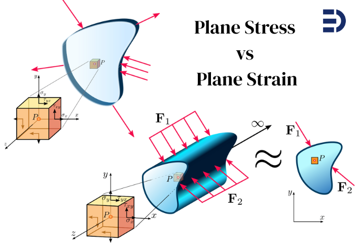
Plane stress is a condition where stresses in one particular direction (the thickness direction) are assumed to be zero. In simpler terms, imagine a very thin object loaded in its own plane – it can’t build up significant stress through its tiny thickness, so we approximate those out-of-plane stresses as zero. Formally, for plane stress we assume:
\varepsilon_z = \gamma_{xz} = \gamma_{yz} = 0meaning no normal stress or shear stress acts perpendicular to the thin plane. The material is free to deform (expand or contract) through its thickness, since there’s no constraint in that direction. (Here, z
denotes the thickness/out-of-plane direction.)
When does this happen? Plane stress is typical in thin flat plates or sheets under in-plane loading. For example, think of a sheet metal panel being pulled in tension. Almost all the stress is in the plane of the sheet (along length and width); the sheet is so thin that through-thickness stress is negligible. Another example is the surface of any object – at a free surface, there’s no stress acting from outside, so the top fibers of a thin aircraft wing or a car body panel can be in near-plane-stress condition. In fact, the very surface of a thick part itself is a plane stress condition (no external pressure on it). This is why plane stress is a perfect assumption at free boundaries of a structure.
In plane stress FEA models, we use 2D elements that only have in-plane stress components. Many solvers let you specify a thickness value for these 2D elements, so they know how much material the model represents (this matters for computing forces, weight, etc.). But the stress state through the thickness is uniform and there’s no \sigma_z by definition. Interestingly, because there’s no resistance through thickness, a plane stress model can still compute a through-thickness strain (thinning or thickening). For instance, a stretched plate in plane stress will thin down according to Poisson’s ratio – a result some FEA programs can output as an extra strain (\varepsilon_z
) even though \sigma_z = 0
. This reinforces that plane stress allows the material to freely contract/expand out-of-plane.
Summary: Plane stress is best for thin objects (think 2D sheet-like structures) where all significant forces lie in the plane. It’s like treating your object as a sheet of paper – it can stretch or shear in its plane, and it might get a bit thinner or thicker, but it won’t feel any direct stress through the thickness.
What is Plane Strain?
Now let’s flip the scenario. Plane strain is essentially the opposite assumption: here we assume deformations in one direction are zero. In a very thick or long object, the material is so constrained in the long direction that it cannot expand or contract along that axis – effectively, the strain in that direction is zero. In other words, the object is “stuck” not being able to deform out-of-plane. Formally, for plane strain we assume:
\varepsilon_z = \gamma_{xz} = \gamma_{yz} = 0meaning no normal strain or shear strain occurs in the z
(out-of-plane) direction. (Here \gamma
represents shear strain.) Another way to say this: the out-of-plane displacement is zero across the whole model. Because the material is not allowed to move in z
, it can build up out-of-plane stress (\sigma_z) instead. In plane strain conditions, \sigma_z is generally not zero – in fact, it will be whatever value is needed to enforce \varepsilon_z =0
(the material will generate a stress to resist any would-be z
deformation).
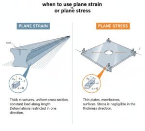
When is plane strain a good assumption? Usually for thick structures or long continuous geometry where the section we model is effectively in the middle of a very deep body. Classic examples: consider the cross-section of a massive concrete dam or an infinitely long tunnel cross-section. The dam is so thick (or the tunnel so long) in the out-of-plane direction that any deformation we consider in the cross-section doesn’t extend to the ends – the material far away prevents z
deformation, so each cross-section behaves as if it’s in plane strain. Another example: deep inside a large bulk of material (far from free surfaces), the material can’t bulge out because there’s more material all around. So engineers use plane strain to model, say, the interior of a wide foundation or the center of a thick plate under load. In these cases, we assume every cross-section along the long dimension experiences the same deformation pattern, so analyzing one slice with $\epsilon_z=0$ is accurate.
In FEA, a plane strain model uses 2D elements that allow no deformation in the thickness direction. You typically do not assign a physical thickness (since we consider it infinite or sufficiently large). Instead, loads are interpreted as per-unit-length. Because \varepsilon_z =0
, the plane strain elements will report an out-of-plane stress \sigma_z internally. This stress represents the constraint from the rest of the long structure. Plane strain elements provide a good approximation for the interior of thick bodies loaded in-plane – basically treating a slice as if the slice is part of an infinitely long/prismatic structure.
Summary: Plane strain is ideal for thick or elongated objects (think 2D slice of a long 3D body) where the out-of-plane deformation is negligible. It’s like slicing a block from the middle of an infinitely long object – that slice can’t move in the long direction because it’s as if the slice is part of a never-ending continuum in that direction. So, it strains only in-plane, not out-of-plane.
Plane Stress vs Plane Strain: Key Differences
Let’s put the two side by side. Both are 2D approximations, but they represent opposite limiting cases:
- Stress vs Strain assumption: Plane stress assumes out-of-plane stresses are zero (\sigma_z =0), while plane strain assumes out-of-plane strains are zero (\varepsilon_z =0). In plane stress the material is unrestrained through thickness (no \sigma_z resistance), whereas in plane strain the material is fully restrained (no \varepsilon_z deformation) and can carry a \sigma_z.
- Geometry context: Plane stress corresponds to thin geometry (small thickness). Plane strain corresponds to thick or long geometry (large thickness/length). You can loosely remember it as:
- Plane Stress = no stress through thickness (thin part).
- Plane Strain = no strain (deformation) through thickness (thick part).
- Examples: Plane stress: thin plate, sheet metal, surface of a part. Plane strain: dam cross-section, geotechnical soil slice under a long footing, interior of a wide component.
- FEA Element type: Plane stress uses 2D elements with a defined thickness (e.g., in Abaqus CPS4 elements) – they carry in-plane stress only. Plane strain uses 2D elements with no thickness (infinitely thick) (e.g., Abaqus CPE4 elements) – they allow in-plane strain only. In practice, many codes let you choose plane stress or plane strain formulation when setting up a 2D model.
- Results and behavior: A plane strain model is usually stiffer than a plane stress model for the same scenario, because it doesn’t allow that extra out-of-plane Poisson expansion. That often means plane strain predicts higher constraint and often higher stress than plane stress for the same loading, all else equal. For instance, if you take a problem and run it once assuming plane stress and once assuming plane strain, the plane strain case may show bigger reaction forces or higher stress because the material can’t relax by expanding out-of-plane. Neither is “more realistic” without context – it depends on your actual 3D situation (more on choosing the right one next).
- Reality check: Neither assumption is exactly true in a real 3D object except in limiting cases. Real structures might be somewhere in between. For example, an object of moderate thickness isn’t perfectly plane stress or plane strain – it’s partially constrained. For very thick objects, plane strain is a closer approximation (especially in the middle region), and for very thin ones, plane stress is closer. There is also an in-between concept called generalized plane strain (which allows a constant strain in the out-of-plane direction) for cases that are not strictly one extreme or the other. But in most engineering use cases, we try standard plane stress or plane strain first to simplify the problem.
When to Use Plane Stress vs Plane Strain
Choosing between plane stress and plane strain comes down to geometry and loading conditions. Here are some guidelines on when to use each assumption:
- Use Plane Stress if:
- The part or region is very thin in one dimension compared to the other two. For example, a thin sheet, plate, or wall where thickness is much smaller than length/width. Loaded in its plane, such a part can’t develop significant through-thickness stress.
- The stresses of interest are in-plane (no significant out-of-plane forces). A thin roof slab under in-plane membrane forces, a printed circuit board under in-plane thermal stress, or the skin of an aircraft under tension are good candidates.
- You want to approximate the surface behavior of a thicker object. Even a thick object has plane stress at its free surfaces (surface elements feel no \sigma_z on the outside). So you might use a plane stress model to estimate surface stresses of a thick plate loaded in-plane (bearing in mind the interior will differ).
- Use Plane Strain if:
- The structure is very thick or long in one dimension, and you are focusing on a cross-section away from the ends. Examples: the mid-span cross-section of a long dam or retaining wall, the cross-section of a long pipeline or tunnel (assuming uniform conditions along length), or the interior region of a wide roll of material being compressed.
- The out-of-plane boundaries are constrained or you can assume the slice you’re modeling behaves as if it’s infinitely deep. For example, soil under a long strip footing can be analyzed with plane strain – the footing extends far, so the soil deformation in one cross-section is representative of any slice along that long footing.
- You’re dealing with a situation where through-thickness strain is negligible due to the geometry. For instance, in a very thick pressure vessel or a very large forging, any given small section might not experience noticeable thickness change when loaded; plane strain could be suitable to simplify analysis.
- Not sure? A quick test is geometry ratio: if the length in one direction >> other dimensions, plane strain might fit; if the thickness << other dimensions, plane stress might fit. Also consider the boundary conditions: plane strain strictly assumes no out-of-plane motion, which really only holds true if something (or a lot of material) restrains that motion. If the ends are free, true plane strain might not hold at the ends (there, a generalized plane strain or full 3D might be more accurate). On the flip side, just because something has free surfaces doesn’t automatically mean the whole interior is plane stress – thick interiors will still develop \sigma_z
if gradients exist. So always tie the assumption back to the physical scenario.
Here’s a quick cheat-sheet summary: – Plane strain: interior of a very thick or long component (no \varepsilon_z
). – Plane stress: a very thin component under in-plane loads (no \sigma_z). – If in doubt and the object is moderately thick, be cautious – the state might transition from plane stress at the surface to plane strain in the core. In critical cases (e.g. complex stress gradients, high accuracy needed), a 3D model or more advanced 2D assumption may be warranted.
Modeling Plane Stress and Plane Strain in FEA Software
Once you’ve decided which assumption fits your case, how do you actually implement it in a finite element analysis (FEA)? Most FEA programs support 2D planar models with either plane stress or plane strain formulations. Below are some common software and how you set up plane stress vs plane strain:
- Abaqus: In Abaqus/CAE, when creating a part you can specify it as a 2D planar part and choose plane stress or plane strain as the deformation type. Abaqus provides dedicated 2D element families: CPS elements (Continuum Plane Stress) for plane stress, and CPE elements (Continuum Plane Strain) for plane strain. For example, CPS4 is a 4-node plane stress element and CPE4 is the 4-node plane strain version. If using Abaqus input files, you’d pick the element type accordingly. When using plane stress in Abaqus, you must assign a section thickness (default is usually 1.0 if not specified). This thickness should be the actual thickness of your thin part if you want stresses and strains to scale correctly. Abaqus will use that thickness to compute out-of-plane properties like load per area. For plane strain, you typically don’t provide a thickness – effectively it’s considered a unit thickness by default (since the model is a slice of an infinitely thick part). Make sure your loads in plane strain are given per unit thickness. For example, apply pressure loads (force per area) or if applying a total force, understand that Abaqus (and most codes) interpret it as per 1.0 thickness for plane strain.
- ANSYS: In ANSYS Mechanical (Workbench), you can specify a 2D analysis and choose between plane stress or plane strain for the analysis type (often when you define the 2D environment, it asks if the model is plane stress, plane strain, or axisymmetric). In ANSYS APDL, classic element types like PLANE182 or PLANE183 have key options to toggle plane stress vs plane strain. For instance, PLANE183 KEYOPT(3) = 0 is plane stress (with a thickness input) and = 1 is plane strain. If you use plane stress, you’ll assign a “thickness” real constant or section property. If you use plane strain, ANSYS assumes unit thickness by default (since there’s no actual thickness to input). Be careful with loads: For plane strain in ANSYS, forces should be given as force per unit thickness. In fact, if you apply a force on a plane strain model as if it were a thin part, you might get unrealistically high stress. One ANSYS expert notes: in plane strain, your loads are essentially interpreted per 1.0 thickness. So if your real structure is, say, 10 m long (out-of-plane) and you know the total force it takes, you should distribute that as force per meter in the 2D model. ANSYS also offers a “generalized plane strain” element if needed, but for most cases you stick to plane stress or plane strain.
- COMSOL Multiphysics: In COMSOL, you would choose a 2D Solid Mechanics physics. Within that, there is a setting for Plane Stress, Plane Strain, or Generalized Plane Strain under the 2D Approximation settings. For plane stress, COMSOL will require a thickness value (default can be 1 if not set). For plane strain, it knows $\epsilon_z=0$ and doesn’t need a thickness for stress calculations (though you might still specify a thickness if you want to calculate forces or masses; COMSOL can use an arbitrary thickness for those purposes). COMSOL makes it straightforward: you just pick the assumption and the software adjusts the equations accordingly. The user interface even reminds you by expanding a “Thickness” section if you choose plane stress.
- Other Software: Most other FEA packages have similar approaches. For example, MSC Nastran/Patran or Siemens Femap: you would use 2D elements (CQUAD4, etc.) and specify if it’s a plane stress mat vs plane strain (usually via material properties or element properties). SolidWorks Simulation and Autodesk Inventor allow 2D simplification studies where you indicate if it’s a thin (plane stress) or thick (plane strain) model. The key is always: define a 2D model, then pick one of the assumptions in the element or analysis settings. And don’t forget to set or note the thickness for plane stress models, as needed.
Important modeling tips: When using these 2D assumptions, double-check that your boundary conditions and loads make sense in 2D. For instance, if you had a 1000 N force on a thin plate in 3D, and you model it as plane stress with 1 mm thickness, you should apply 1000 N in the 2D model and specify thickness = 1 mm (the FEA code will internally calculate stress = force/(thicknesswidth)). If you model it as plane strain (essentially thickness = infinite), that 1000 N should be applied as 1000 N per unit thickness*, which effectively is a very different load if misinterpreted. Many errors in plane strain models come from not adjusting loads – e.g., getting 10× higher stress because the software assumed your 1000 N was for just 1 unit of thickness. Always consult the documentation: some codes implicitly treat all 2D loads as per unit thickness, others scale by a thickness parameter.
Another tip: mesh and element order considerations are similar in 2D as in 3D, but note that plane strain elements can sometimes appear overly stiff if the situation isn’t truly plane strain. This is because the out-of-plane constraint might lock some deformation modes. Using higher-order or reduced-integration elements can alleviate artificial stiffness (shear locking) in plane strain analyses. If you ever see plane strain results that seem off, question whether the assumption is valid and whether your mesh is fine enough.
Real-World Example for Context
To solidify the concepts, let’s quickly consider a plate with a hole under tension – a classic example. If the plate is very thin (like a sheet metal sample), modeling a 2D section with a plane stress assumption works well: you’ll capture the stress concentration around the hole with good accuracy, and out-of-plane stress is minimal (the plate can freely thin as it stretches). Now imagine the plate is extremely thick (like a thick block with a drilled tunnel through it). In the middle of that block (far from the ends), the material can’t contract in thickness when pulled – it’s constrained by surrounding material – so a plane strain model of the cross-section would be more appropriate. In fact, a full 3D analysis of that scenario shows that as thickness increases, the stress state near the hole transitions: the surface stays near plane stress, but deep inside it approaches plane strain. This transition is exactly why picking the right assumption matters. Plane stress would under-predict the constraint in a thick body, while plane strain in a thin body would over-predict stiffness and stress (as one Reddit user found out with a 10× stress error). So always tailor the choice to your scenario.
Wrapping Up
Plane stress and plane strain are powerful simplifications in solid mechanics. By recognizing that a thin sheet barely carries thickness stress, or a long solid has no room to strain out-of-plane, we turn 3D problems into efficient 2D models. We discussed what each assumption means physically – one with no out-of-plane stress (plane stress) and one with no out-of-plane strain (plane strain). We saw typical cases and guidelines for each, and even touched on how to implement them in popular FEA software. Use plane stress for your thin, in-plane-loaded structures, and plane strain for thick, constrained ones. If you apply these assumptions appropriately, you can get accurate insights with a fraction of the computational cost of 3D analysis.
That said, always keep an engineering eye open: ensure the simplification is valid, and when in doubt, do a quick 3D sanity check or consider more advanced 2D options (like generalized plane strain) for borderline cases. By mastering these concepts, you can confidently tackle a wide range of problems from aircraft skins to dam foundations with the right tool for the job.
Need help with your simulation or not sure which assumption to use? Our team at EngineeringDownloads is committed to addressing all your CAE and FEA needs, from consulting on model setup to fully executing analysis projects. Your feedback and success stories drive us to keep delivering top-notch engineering solutions. If you have any questions or encounter challenges with plane stress, plane strain, or any simulation, please reach out to us through our social media or WhatsApp – we’re here to help bring clarity to your CAE problems and ensure your projects succeed.
Written by: Saman Hosseini


