The Oil & Gas industry is a cornerstone of global energy, driving innovation and demanding the highest standards of engineering excellence. From the remote depths of the ocean to vast onshore processing facilities, engineers face a unique set of challenges related to extreme environments, stringent safety regulations, and the immense scale of operations.
At its core, Oil & Gas engineering is about ensuring the safe, efficient, and reliable extraction, processing, and transportation of hydrocarbons. This isn’t just about massive machinery; it’s about meticulous design, advanced simulation, and an unwavering commitment to structural integrity and operational safety.

Oil rig in the North Sea by Arne Håkon Tjelle, CC BY-SA 2.0
The Backbone of Industry: Understanding Oil & Gas Engineering
Oil & Gas engineering is a multi-faceted discipline that intersects mechanical, structural, civil, chemical, and materials engineering. It’s a field where theoretical knowledge meets practical application in some of the harshest conditions on Earth.
What Makes Oil & Gas Engineering Unique?
- Extreme Operating Environments: Components must withstand immense pressures (hundreds of bars), high temperatures (over 200°C), and highly corrosive fluids. Subsea structures contend with deep-water pressures, low temperatures, and marine fouling.
- Scale and Complexity: From kilometer-long pipelines and massive offshore platforms to intricate refinery units, the sheer size and interconnectedness of systems present unique design and analysis challenges.
- Safety and Regulatory Demands: The potential for catastrophic failure necessitates rigorous safety protocols and adherence to international standards and regulations. Environmental impact is also a major consideration.
- Dynamic Loads: Offshore structures are constantly subjected to dynamic environmental loads from waves, currents, and wind, leading to fatigue concerns.
Key Engineering Disciplines at Play
- Structural Engineering: Designing and analyzing platforms, pipelines, risers, and onshore facilities to resist static and dynamic loads, including seismic, wind, wave, and blast events.
- Mechanical Engineering: Focuses on machinery, rotating equipment, pressure vessels, heat exchangers, and drilling equipment.
- Process Engineering: Optimizing fluid flow, separation, and chemical reactions within refineries and processing plants.
- Materials Science: Selecting materials that can resist corrosion, fatigue, high temperatures, and embrittlement in aggressive environments.
- Subsea Engineering: Specializing in equipment and infrastructure for underwater oil and gas production and transport.
Structural Integrity: A Non-Negotiable in Oil & Gas
Maintaining the structural integrity of assets is paramount for safety, environmental protection, and operational continuity in the Oil & Gas sector. A single failure can have devastating consequences.
Challenges in Structural Design and Analysis
- Fatigue Loading: Cyclic stresses from wave action, wind gusts, and vibrations can lead to fatigue crack initiation and propagation, even below yield strength.
- Corrosion and Erosion: Exposure to seawater, H2S, CO2, and abrasive particulates can degrade material properties over time, reducing load-carrying capacity.
- Extreme Weather Events: Hurricanes, typhoons, and ice loads impose extraordinary forces on structures, requiring robust designs.
- Accidental Loads: Designs must consider potential impact from vessels, dropped objects, and internal or external explosions (blast loading).
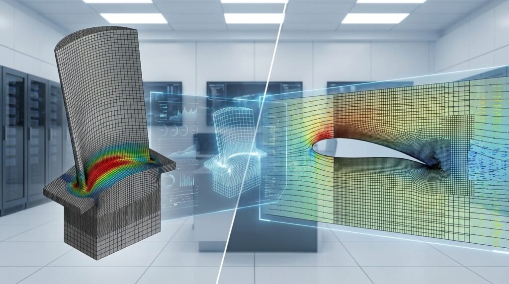
Applying Finite Element Analysis (FEA) for Structural Components
FEA is an indispensable tool for engineers designing and assessing the structural integrity of Oil & Gas assets. It allows for detailed stress, strain, deformation, and fatigue analyses of complex geometries under various loading conditions.
- Common Applications: Pressure vessels, pipelines (onshore and offshore), risers, topside modules, jacket structures, foundations, and wellhead equipment.
- Typical Tools: Industry-standard software like Abaqus, ANSYS Mechanical, and MSC Nastran are widely used for their advanced material models, nonlinear capabilities, and robust solvers.
Practical FEA Workflow
- Defining the Problem and Scope: Clearly identify the objective (e.g., stress check, fatigue life, buckling analysis), relevant loads (pressure, temperature, environmental), boundary conditions, material properties, and failure criteria (yield, ultimate, fracture toughness).
- Geometry Preparation & Meshing: Utilize CAD tools like CATIA or SolidWorks to create or simplify geometries. Import into your FEA software (Abaqus, ANSYS) for meshing. Focus on mesh quality – element aspect ratio, Jacobian, skewness are critical for accuracy, especially in stress concentration regions.
- Material Models & Boundary Conditions: Assign appropriate material models (linear elastic, elastoplastic, hyperelastic). Define boundary conditions (fixed, simply supported, displacement constraints) and apply loads. Don’t forget contact definitions for assemblies.
- Running the Analysis & Post-Processing: Execute the solver. After successful completion, review results for stress, strain, deformation, reaction forces. Visualize stress distributions to identify hot spots and critical areas. For fatigue analysis, extract stress histories and apply fatigue damage models.
Verification & Sanity Checks for FEA
- Mesh Independence Studies: Run the analysis with successively finer meshes to ensure results converge and are not overly dependent on element size. Ensure appropriate element types are used (e.g., solid elements for thick sections, shell elements for thin-walled structures).
- Boundary Condition Validation: Check reaction forces and moments to confirm they align with applied loads. Verify that boundary conditions don’t over-constrain or under-constrain the model, preventing rigid body motion where it shouldn’t occur.
- Convergence Criteria & Energy Balance: For nonlinear analyses, monitor convergence of iterative solutions. Check the internal and external energy balance to ensure equilibrium is achieved throughout the simulation.
- Validation Against Hand Calculations or Field Data: For simpler load cases, compare FEA results with analytical solutions or established design formulas. If available, validate critical results against real-world sensor data or experimental tests.
- Sensitivity Analysis for Key Parameters: Assess how changes in critical input parameters (material properties, load magnitudes, geometric tolerances) affect the output. This provides insight into the robustness of your design.
Fitness-for-Service (FFS) Assessments (API 579 / FFS Level 3)
When in-service equipment develops damage (e.g., corrosion, cracking, dents), FFS assessments determine if it can safely continue operating for a specified period. This is crucial for avoiding costly shutdowns.
- When to use FFS: When defects are detected, equipment exceeds design life, or operating conditions change.
- Levels of Assessment: API 579 offers three levels. Level 1 is a conservative screening, Level 2 requires more detailed calculations, and Level 3 involves advanced engineering analysis, often requiring detailed FEA.
- Role of Advanced FEA in Level 3: For Level 3 FFS, FEA is used to precisely model crack tip stress fields, predict crack propagation rates (using fracture mechanics principles), and estimate remaining useful life. This requires sophisticated material models and often specialized element types for crack growth analysis.
- Common Pitfalls: Inaccurate flaw characterization (size, shape, location), incorrect material properties (especially fracture toughness), simplified loading assumptions, and neglecting residual stresses can lead to unsafe or overly conservative FFS recommendations.
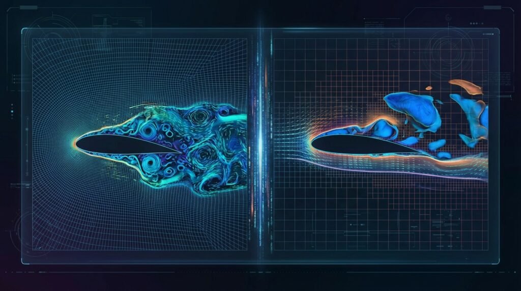
Fluid Dynamics in Oil & Gas: From Flow Assurance to Safety
Understanding fluid behavior is critical across the Oil & Gas lifecycle, from reservoir extraction to processing and distribution. Computational Fluid Dynamics (CFD) provides powerful insights.
Computational Fluid Dynamics (CFD) Applications
- Flow Assurance in Pipelines: Simulating multiphase flow (oil, gas, water) to predict pressure drop, slugging, hydrate formation, and wax deposition, which can lead to blockages.
- Separators and Processing Equipment: Optimizing the design of separators, heat exchangers, and reactors for maximum efficiency and throughput.
- Combustion Modeling: Analyzing flares, gas turbines, and internal combustion engines for efficiency, emissions, and safety.
- Dispersion Analysis: Simulating the release and dispersion of flammable or toxic gases during leaks or accidental events to assess safety zones and ventilation requirements.
- Aerodynamics of Offshore Structures: Evaluating wind loads on topsides, helidecks, and flare stacks, and ensuring adequate ventilation for enclosed spaces.
Practical CFD Workflow
- Geometry & Meshing for Fluid Domains: Create or clean the fluid domain geometry. Generate a high-quality mesh (structured or unstructured) using tools like ANSYS Meshing, ICEM CFD, or directly within OpenFOAM. Ensure mesh refinement in areas with high gradients (e.g., near walls, mixing zones).
- Physics Setup: Define fluid properties, select appropriate turbulence models (e.g., k-epsilon, SST k-omega for RANS; LES for transient detailed flow), multiphase models (e.g., VOF, Eulerian-Eulerian), and any chemical reactions or heat transfer models.
- Solver Settings & Convergence: Choose solver algorithms (e.g., pressure-based, density-based). Set appropriate numerical schemes and convergence criteria for residuals (e.g., 1e-4 or 1e-5). Monitor mass and energy balances.
- Post-Processing & Interpretation: Visualize flow fields (velocity vectors, streamlines), pressure contours, temperature distributions, and species concentrations. Extract quantitative data like pressure drop, forces, and mass flow rates. Look for recirculation zones, separation, and uniform mixing.
CFD Verification & Sanity Checks
- Grid Independence Studies: Similar to FEA, refine the mesh and observe if key results change significantly. A grid-independent solution is essential for reliable results.
- Boundary Condition Realism: Ensure inlet velocities, pressures, and outlet conditions accurately reflect the physical system. Check that velocity profiles at inlets are fully developed if required.
- Residual Convergence & Mass/Energy Balance: Monitor residuals to ensure they drop sufficiently. Verify that the mass and energy entering and exiting the domain are balanced. Significant imbalances indicate a problem.
- Physical Interpretation & Expected Trends: Do the results make physical sense? Are pressure drops positive in the direction of flow? Are temperature gradients consistent with heat sources? Compare with simplified analytical models or experimental data if available.
Optimization, Automation, and Data-Driven Engineering
Modern Oil & Gas engineering increasingly relies on advanced computational techniques to optimize designs, enhance efficiency, and reduce human error.
Leveraging CAD-CAE Workflows
Integrating Computer-Aided Design (CAD) with Computer-Aided Engineering (CAE) streamlines the entire product development process.
- Seamless Integration: Design changes made in CAD software (e.g., CATIA) can be quickly propagated to analysis models in FEA/CFD tools, reducing manual rework.
- Parametric Modeling: Allows engineers to quickly explore design alternatives by varying key dimensions and instantly updating the analysis model, facilitating optimization studies.
Automation with Python and MATLAB
Scripting languages like Python and MATLAB are powerful allies for automating repetitive tasks and orchestrating complex simulation workflows.
- Scripting Pre-processing: Automate mesh generation parameters, assign material properties, apply loads and boundary conditions, or even generate input files for Abaqus or ANSYS directly from a script.
- Post-processing Automation: Extracting specific results (e.g., maximum stress, average temperature), generating custom plots, or creating detailed reports from simulation output. Python’s data analysis libraries (NumPy, Pandas, Matplotlib) are invaluable here.
- Parametric Studies and Optimization Loops: Run hundreds or thousands of simulations automatically by varying design parameters, then analyze the results to find optimal designs based on performance criteria (e.g., minimum weight, maximum fatigue life).
Benefits of Automation
- Reduced Human Error: Automating repetitive tasks minimizes the chance of manual input mistakes.
- Faster Iteration Cycles: Engineers can explore more design options in less time, accelerating the design process.
- Enabling Complex Optimizations: Allows for sensitivity studies and optimization algorithms that would be impractical to perform manually.
For engineers tackling complex simulations or needing to accelerate their design cycles, remember that services like affordable HPC rental for running large models, online courses, and project consultancy are available to empower your work and enhance your engineering capabilities.
Essential Checklists & Troubleshooting for Oil & Gas Simulations
Even with advanced tools, successful simulations require methodical planning and careful troubleshooting.
Pre-Analysis Checklist
- Clear Objectives: What specific questions is the simulation answering? (e.g., pressure drop, stress concentration, buckling load).
- Material Properties: Are all properties (elastic modulus, yield strength, density, thermal conductivity) correctly defined for the operating temperature and environment?
- Loads and Boundary Conditions: Are all relevant loads (pressure, temperature, wind, wave, gravity) identified and accurately applied? Are boundary conditions realistic and sufficient?
- Simplifications: Are any geometric or loading simplifications justified and their impact understood?
- Validation Data: Is there any experimental data, hand calculation, or previous simulation to compare initial results against?
During-Analysis Troubleshooting
- Convergence Issues: If your FEA or CFD solution isn’t converging, check mesh quality, time step (for transient), solver settings, and ensure boundary conditions are well-posed.
- Unexpected Results: If results are wildly different from expectations, re-check units, load magnitudes, material properties, and contact definitions. Large deformations or unrealistic stresses often point to input errors.
- Numerical Instabilities: For CFD, high aspect ratio cells, poor mesh quality, or overly aggressive numerical schemes can lead to oscillations or divergence.
Post-Analysis Review
- Physical Realism: Do the deformations, stresses, and flow patterns look physically plausible? Are peak stresses in expected locations?
- Sensitivity: How sensitive are the key results to minor changes in input parameters (e.g., material strength tolerances, load fluctuations)?
- Reporting: Clearly document assumptions, methodology, results, and conclusions. Highlight limitations and areas for further investigation.
Here’s a quick guide to common simulation issues and practical solutions:
| Problem Type | Symptom | Common Causes | Practical Solution |
|---|---|---|---|
| FEA: Non-Convergence | Solver stops or warns about large increments, no solution reached. | Poor mesh quality, over-constraint, too large load increments, material non-linearity. | Improve mesh, check BCs, reduce load step size, verify material model stability. |
| FEA: Unrealistic Deformation | Structure moves excessively or behaves like a rigid body. | Missing boundary conditions, incorrect units, very soft material properties. | Ensure proper constraints (no rigid body motion), verify units, double-check material inputs. |
| CFD: Divergence | Residuals fluctuate wildly, solution explodes or becomes unstable. | Poor mesh quality, unsuitable turbulence model, aggressive under-relaxation, incorrect BCs. | Refine mesh, switch to a more robust turbulence model, increase under-relaxation factors, re-check BCs. |
| CFD: Non-Physical Results | Negative pressures, reverse flow where unexpected, incorrect temperature profiles. | Incorrect fluid properties, wrong boundary conditions, inadequate grid resolution in critical areas. | Verify all physical inputs, ensure BCs match reality, perform grid independence study. |
| Both: Excessive Run Time | Simulation takes hours/days longer than expected. | Overly fine mesh, complex contact, transient analysis with small time steps, insufficient HPC resources. | Optimize mesh density, simplify contact definitions, adjust time step, consider HPC rental. |
Navigating Regulatory and Safety Standards
Compliance with industry standards is not optional; it’s a fundamental part of Oil & Gas engineering. These standards ensure safety, reliability, and environmental protection.
Key Standards and Best Practices
- API (American Petroleum Institute): Provides a vast array of standards for equipment design, operation, and maintenance (e.g., API 6A for wellhead equipment, API 579 for FFS).
- ISO (International Organization for Standardization): Many ISO standards apply, covering quality management (ISO 9001), environmental management (ISO 14001), and specific industry applications.
- DNV (Det Norske Veritas): A leading classification society, DNV offers comprehensive rules and standards, especially for offshore and maritime operations.
- Understanding and Incorporating Standards: Engineers must be familiar with the relevant standards for their specific projects and integrate their requirements into design calculations, material selection, fabrication procedures, and operational guidelines.
The Future of Oil & Gas Engineering
The industry is continuously evolving, driven by technological advancements and global energy demands.
- Digitalization and AI/ML: Integrating artificial intelligence and machine learning for predictive maintenance, optimizing drilling operations, and enhancing seismic data analysis.
- Remote Operations: Increased automation and remote monitoring of facilities to improve safety and reduce operational costs.
- Energy Transition: Oil & Gas companies are increasingly involved in renewable energy projects (e.g., offshore wind foundations), carbon capture, utilization, and storage (CCUS), and hydrogen production. This requires engineers to adapt their skills to new energy technologies.
- Sustainable Practices: A growing focus on reducing environmental impact, including methane emission reduction, water management, and responsible decommissioning of assets.
The Oil & Gas sector remains a dynamic and challenging field for engineers. By mastering advanced simulation techniques, adhering to rigorous standards, and embracing technological innovation, engineers will continue to drive progress and ensure the safe and efficient delivery of energy resources.
Further Reading
For more detailed information on industry standards and practices, refer to the American Petroleum Institute (API) website.