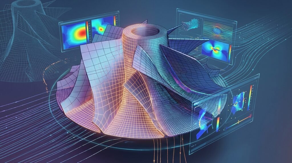
The Foundation of Advanced FEA: Understanding MSC Patran
In the realm of Finite Element Analysis (FEA) and Computer-Aided Engineering (CAE), robust pre-processing and insightful post-processing are paramount for accurate and reliable simulation results. MSC Patran stands as a premier solution in this domain, serving as a powerful, multi-purpose pre- and post-processor that facilitates the entire simulation workflow, from geometry idealization to advanced results visualization. Developed by MSC Software (now part of Hexagon MI), Patran is intricately linked with industry-standard solvers like MSC Nastran, yet it offers extensive interoperability with a broad spectrum of other solvers, including Abaqus, ANSYS Mechanical, and even CFD tools like Fluent/CFX and OpenFOAM.
This article provides an engineer-to-engineer guide to leveraging MSC Patran effectively. We’ll delve into its core capabilities, outline practical workflows, emphasize critical verification steps, and offer insights into integrating Patran within comprehensive CAE ecosystems. Whether you’re tackling structural integrity assessments for oil & gas components, optimizing aerospace structures, or performing complex biomechanics simulations, mastering Patran is key to unlocking the full potential of your analyses.
MSC Patran’s Pivotal Role in Modern CAE Workflows
MSC Patran acts as the central hub for preparing your CAD models for analysis and interpreting the vast amounts of data generated by solvers. Its versatility makes it indispensable across various engineering disciplines.
Bridging CAD to Solver: The Pre-Processing Imperative
Before any numerical analysis can begin, a physical design must be translated into a mathematical model suitable for a solver. This is where Patran excels:
- Geometry Import and Cleanup: Patran can import CAD models from various formats (e.g., STEP, IGES, Parasolid, native CATIA files), offering tools to repair faulty geometry, remove small features (defeaturing), and simplify complex assemblies. For thin-walled structures, mid-surfacing is a crucial capability to generate 2D shell elements, significantly reducing computational cost while maintaining accuracy.
- Meshing: The process of discretizing the continuous geometry into finite elements is perhaps the most critical pre-processing step. Patran provides a comprehensive suite of meshing tools for 1D (beams, rods), 2D (shells), and 3D (solids) elements, allowing engineers to generate high-quality meshes tailored to specific analysis requirements.
- Material and Property Definition: Assigning realistic material models (isotropic, anisotropic, hyperelastic, etc.) and element properties (thicknesses, beam cross-sections) is fundamental. Patran simplifies this by providing libraries and intuitive interfaces.
- Loads and Boundary Conditions: Accurately applying loads (pressure, force, temperature, acceleration) and boundary conditions (constraints, prescribed displacements) is essential for simulating real-world scenarios. Patran offers robust tools for defining these, often allowing for field function definitions for complex spatial or temporal variations.
Interpreting Results: Beyond Contour Plots
Once a solver completes its calculations, the raw output data needs to be processed into actionable insights. Patran’s post-processing capabilities are extensive:
- Visualizing Deformations and Stresses: Standard contour plots, vector plots, and animations help visualize structural response, stress concentrations, and failure modes. This is vital for FFS Level 3 assessments where detailed stress analysis is required.
- Data Extraction and Manipulation: Engineers can extract results at specific nodes or elements, create path plots, XY plots, and perform mathematical operations on results data. This allows for detailed quantitative analysis, such as stress linearization across section cuts.
- Report Generation: Patran facilitates the creation of comprehensive reports, allowing for easy sharing of results and conclusions.
Essential Workflows in MSC Patran: A Practical Guide
Let’s walk through a typical, practical workflow for a structural analysis using MSC Patran.
Step-by-Step Geometry Preparation
- Import CAD Model: Navigate to
File > Import > Modeland select your CAD file (e.g., .STEP, .X_T). - Geometry Cleanup: Use
Geometry > Solid > CleanuporGeometry > Surface > Cleanuptools. Look for small edges, sliver surfaces, and gaps. The ‘Equivalence’ tool (Geometry > Solid > Equivalence) is critical for merging coincident entities. - Defeaturing and Idealization: For features like small fillets or holes irrelevant to the primary analysis, use
Geometry > Solid > Delete > Feature. For thin-walled structures (e.g., sheet metal components in aerospace), useGeometry > Surface > Midsurfaceto generate representative 2D surfaces.
Meshing Strategies for FEA Accuracy
Meshing is often the most time-consuming and critical pre-processing step. Patran offers diverse approaches:
2D Meshing Techniques for Shell Elements
For mid-surfaced geometries or thin solids, 2D shell meshing is efficient. Access via Elements > Create > Mesh.
- Isomesh: Best for regularly shaped surfaces, generating well-ordered quad elements.
- P-mesh: More flexible for complex geometries, typically generating mixed quad/tri elements or tri-dominant meshes.
- Mesh Control: Apply mesh seeds (
Elements > Create > Mesh Control) on edges or surfaces to refine mesh density in critical areas like stress concentration zones. This is crucial for accurately capturing stress gradients in FFS Level 3 analyses.
3D Meshing Techniques for Solid Elements
For bulky components or where through-thickness stresses are important (e.g., pressure vessels in Oil & Gas):
- Tetrahedral (Tet) Meshing: Most common for complex 3D geometries. Use
Elements > Create > Mesh > 3D. ‘Free Tet’ meshing is fully automated, while ‘Mapped Tet’ allows more control. - Hexahedral (Hex) Meshing: Offers higher accuracy and faster convergence but is challenging for complex shapes. Patran allows ‘Mapped Hex’ on simpler volumes or ‘Swept Hex’ from a 2D mesh.
- Element Quality Checks: After meshing, always perform quality checks via
Elements > Verify > Element Quality. Key metrics include Aspect Ratio, Skew, Jacobian, and Warping for shells.
Table 1: Common Mesh Quality Metrics and Typical Guidelines for Nastran
| Metric | Description | Typical Desirable Range (Nastran) | Impact of Poor Quality |
|---|---|---|---|
| Aspect Ratio | Ratio of longest edge to shortest edge. | < 5 (ideal), < 20 (acceptable) | Reduced accuracy, solver convergence issues. |
| Skew Angle (Quads/Tris) | Deviation of an element’s angle from ideal (90°/60°). | < 45° (ideal), < 70° (acceptable) | Reduced accuracy, particularly for stress calculations. |
| Jacobian | Measure of element distortion. | > 0.6 (ideal), > 0.2 (acceptable) | High distortion leads to inaccurate stiffness. |
| Warping (Shells) | Deviation of a quad element from planarity. | < 5° (ideal), < 10° (acceptable) | Inaccurate bending stiffness for shell elements. |
Defining Materials, Properties, and Connections
- Create Materials: Go to
Materials > Create > Isotropic > Manual Input(or select from library). Define Young’s Modulus, Poisson’s Ratio, and Density. For advanced analyses, Patran supports orthotropic, anisotropic, and hyperelastic models. - Create Properties: Navigate to
Properties > Create. For 2D meshes, select ‘2D Planar’ or ‘Shell’ and define thickness. For 3D meshes, ‘Solid’ is default. For beams, define cross-sectional geometry. - Apply Properties: Select the created property and use ‘Apply’ to assign it to relevant elements or geometric entities.
- Connections: For assemblies, define contacts (e.g.,
Loads/BCs > Create > Contact) or fasteners (e.g.,Elements > Create > Connectorfor bolts/welds using rigid elements or beams).
Applying Loads and Boundary Conditions
Access these via Loads/BCs > Create. Visualize your applied conditions using Loads/BCs > Show > Individual.
- Constraints: Apply fixed boundary conditions (e.g., Enforced Motion, Fixed, Pin) to restrict movement. For instance, in a biomechanics analysis of a bone implant, the bone might be ‘Fixed’ at certain points.
- Applied Loads: Define nodal forces, pressures on surfaces, gravity, or prescribed temperatures. For dynamic analyses, time-dependent loads can be defined.
- Field Functions: For spatially varying loads (e.g., non-uniform pressure distribution on a wing, or fluid flow pressure from CFD results), Patran’s Field Functions (
Fields > Create) are invaluable.
Solver Integration and Execution
After defining the analysis model, you need to set up the solver parameters:
- Analysis Setup: Go to
Analysis > Analyze > Entire Model. Select the solver (e.g., ‘MSC Nastran’) and the analysis type (e.g., ‘Static’, ‘Normal Modes’, ‘Buckling’). - Job Submission: Generate the input file (e.g., .bdf for Nastran) and submit the job. Patran can often monitor the solver progress directly.
- Python/MATLAB Automation: For repetitive solver setup tasks or parameter sweeps, advanced users can leverage Python or MATLAB scripts to generate Patran input files or parse solver output for batch processing. EngineeringDownloads.com offers a selection of downloadable Python scripts tailored for common Patran pre-processing tasks and post-processing data extraction, helping to streamline your workflow significantly.
Post-Processing and Critical Insights
Once the solver completes, load the results back into Patran (Analysis > Read Results > Attach XDB or Read Output).
- Deformation & Fringe Plots: Visualize the deformed shape and stress/strain contours (e.g., von Mises stress, principal stresses). Use
Results > Create > Quick Plot. - Vector Plots: Show displacement or force vectors.
- Cutting Planes & Isosurfaces: Examine internal stresses or visualize results within complex 3D models.
- XY Plots: Plot results along paths or over time steps. For FFS Level 3, stress linearization tools can be used to extract surface and membrane stresses.
- Animation: Animate mode shapes or transient responses.
Verification and Sanity Checks in MSC Patran
No simulation is complete without thorough verification. This critical step ensures your model accurately represents the physical problem and that the results are reliable.
Meshing Quality Checklist
- Review Quality Metrics: Always review the element quality report (e.g., aspect ratio, skew, Jacobian, warping). Address elements exceeding acceptable thresholds through re-meshing or local adjustments.
- Visual Inspection: Zoom into critical areas (e.g., high stress gradients, load application points) to visually inspect mesh distribution and element connectivity.
Boundary Condition Validation
- Visualize Applied BCs: Ensure all constraints and loads are applied to the correct entities and in the intended directions. Use Patran’s display options to show symbols for forces, pressures, and constraints.
- Reaction Force/Moment Check: For static analyses, sum reaction forces and moments at constraints. They should balance the applied loads. This is a fundamental sanity check.
Convergence Studies
- Mesh Convergence: Perform simulations with progressively finer meshes (especially in critical regions) and observe if the key results (e.g., peak stress, displacement) converge to a stable value. This ensures your mesh is sufficiently refined.
- Load Step Convergence: For non-linear analyses, check if results are stable with respect to load increments.
Comparison and Validation
- Hand Calculations: For simplified sub-regions or simplified load cases, perform basic analytical calculations to compare against simulation results.
- Compare with Prior Analyses: If available, compare results against similar analyses performed with other tools (e.g., Abaqus, ANSYS) or historical data.
- Experimental Data: When possible, validate critical results against physical test data. While you don’t perform physical tests, your simulation outputs should align with available test data trends.
Sensitivity Analysis
- Material Property Variations: Run analyses with slight variations in material properties (e.g., Young’s Modulus, yield strength) within their expected ranges to understand their impact on results.
- Load/BC Variations: Investigate the sensitivity of results to slight changes in load magnitude, direction, or boundary condition placement. This helps identify robust designs.
Integrating MSC Patran into Broader CAE Ecosystems
While Patran is powerful as a standalone pre/post-processor, its true strength lies in its ability to integrate with other engineering tools.
Synergies with MSC Nastran and Other Solvers
Patran is natively optimized for MSC Nastran, providing a seamless workflow. However, its capability to export generic input decks and import results from other solvers ensures flexibility. You can, for instance, prepare a model in Patran, export it for an Abaqus or ANSYS Mechanical solver, and then import the results back into Patran for uniform post-processing. For CFD simulations, models prepared in Patran can be exported for Fluent/CFX or even OpenFOAM, though specialized CFD pre-processors might offer more dedicated tools for fluid domains.
Scripting and Automation with Python/MATLAB
For repetitive tasks, advanced users can leverage Patran Command Language (PCL) or external scripting languages. Python, for example, can be used to:
- Automate geometry parameterization.
- Generate complex mesh controls.
- Parse solver output files to extract specific data, beyond Patran’s native capabilities.
- Automate report generation from multiple simulation runs.
For engineers seeking to accelerate their learning curve or optimize their existing Patran workflows, EngineeringDownloads.com offers a valuable resource library. This includes downloadable project templates, specialized scripts for Python or MATLAB to automate repetitive pre- or post-processing tasks, and opportunities for expert online consultancy on specific challenges, such as advanced FFS Level 3 analyses or complex biomechanics simulations. These resources are designed to complement your practical application of MSC Patran.
CAD-CAE Seamlessness
Patran supports direct interfaces with leading CAD systems, facilitating design changes and updates. Associativity between the CAD geometry and the FEA model means that changes in the CAD model can often be propagated to the Patran model with minimal re-work, a crucial feature in iterative design processes.
Advanced Tips for MSC Patran Users
Leveraging Field Functions
Field functions in Patran are incredibly powerful for defining complex spatial or temporal variations for materials, loads, boundary conditions, or even element properties. For example, a temperature-dependent material property or a pressure load that varies non-linearly across a surface can be precisely defined using field functions, enhancing the realism of your simulations.
Customizing User Interfaces (PCL)
Patran Command Language (PCL) allows users to create custom menus, forms, and scripts to automate sequences of operations. This can significantly boost productivity for specific, frequently performed tasks within your organization.
Efficient Large Model Handling
For very large models typical in industries like Aerospace or Oil & Gas, Patran offers features like database partitioning, display groups, and efficient graphics rendering to manage computational resources effectively. Utilizing display groups to isolate and work on specific sections of the model can drastically improve performance and user experience.
Conclusion
MSC Patran is more than just a pre- and post-processor; it’s a sophisticated environment that empowers engineers to translate complex physical problems into actionable simulation models. By mastering its comprehensive tools for geometry manipulation, meshing, boundary condition application, and results interpretation, you can significantly enhance the accuracy, efficiency, and reliability of your FEA and CAE projects. Continuous learning and adherence to verification best practices are essential to fully harness the power of MSC Patran in driving innovative and robust engineering solutions across diverse fields.
Frequently Asked Questions (FAQ) about MSC Patran
What is MSC Patran primarily used for in engineering?
MSC Patran is primarily used as a pre- and post-processor for Finite Element Analysis (FEA) and Computer-Aided Engineering (CAE). It provides a comprehensive environment for preparing CAD models for simulation (geometry cleanup, meshing, applying loads and boundary conditions) and for visualizing and interpreting results from various FEA solvers like MSC Nastran, Abaqus, and ANSYS Mechanical.
How does MSC Patran integrate with other FEA solvers?
While MSC Patran has a native and optimized integration with MSC Nastran, it offers robust interoperability with other major FEA solvers. It can export generic input decks (e.g., for Abaqus or ANSYS) and import their respective results files for post-processing, allowing engineers to leverage Patran’s powerful visualization and data extraction tools regardless of the chosen solver.
What are the most critical meshing quality metrics to monitor in Patran?
Key meshing quality metrics to monitor in Patran include Aspect Ratio (ratio of longest to shortest edge), Skew Angle (deviation from ideal element angles), Jacobian (measure of element distortion), and Warping (deviation of a quad element from planarity). Maintaining these metrics within acceptable ranges is crucial for solver convergence and result accuracy.
Can MSC Patran be used for both structural and CFD analysis?
MSC Patran is predominantly recognized for structural mechanics FEA pre/post-processing. While it can prepare geometry and meshes that can be exported for CFD solvers like Fluent/CFX or OpenFOAM, specialized CFD pre-processors might offer more dedicated fluid domain meshing and boundary condition tools. Patran’s strengths lie in solid mechanics modeling.
How can Python or MATLAB enhance an MSC Patran workflow?
Python or MATLAB can significantly enhance Patran workflows through scripting and automation. They can be used to generate complex geometry parameters, automate repetitive meshing tasks, parse and process large solver output files for custom data extraction, and automate report generation. This is particularly useful for parameter studies or when integrating Patran into larger simulation frameworks.
What is the importance of verification and sanity checks in Patran?
Verification and sanity checks are crucial to ensure the reliability and accuracy of simulation results. This includes checking mesh quality, visually validating applied loads and boundary conditions, performing reaction force checks, and conducting convergence studies (e.g., mesh convergence). These steps help identify and mitigate potential modeling errors before relying on the simulation output for critical engineering decisions.