Understanding Mesh Quality Metrics for Robust FEA & CFD Simulations
In the world of Finite Element Analysis (FEA) and Computational Fluid Dynamics (CFD), the quality of your computational mesh isn’t just a detail – it’s fundamental to the accuracy, stability, and convergence of your simulations. A poorly constructed mesh can lead to non-physical results, convergence failures, or excessively long run times, costing valuable engineering hours and project delays.
This guide will demystify mesh quality metrics, offering practical insights and actionable strategies to help engineers like you generate high-quality meshes for reliable and efficient simulations, whether you’re working in structural integrity, oil & gas, aerospace, or biomechanics.

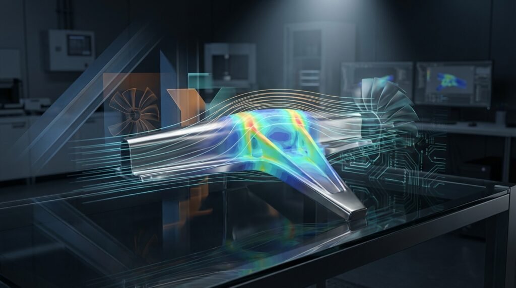
Mesh representation for FEA, illustrating element distribution.
Why Mesh Quality is Non-Negotiable
Imagine trying to analyze stress concentrations around a complex geometry using elements that are highly distorted or poorly shaped. The mathematical approximations performed by your solver (e.g., Abaqus, ANSYS Mechanical, Fluent) would struggle, leading to significant errors. Here’s why mesh quality truly matters:
- Accuracy of Results: Poor quality elements can drastically reduce the accuracy of your solution, particularly in areas with high gradients (stress, temperature, velocity).
- Convergence: Highly distorted elements are a common culprit for simulation non-convergence, especially in non-linear FEA or complex CFD problems.
- Computational Cost: While a very fine mesh might seem like a good idea, a poor quality fine mesh can lead to excessive iteration counts or even prevent a solution from being reached efficiently.
- Stability: Unstable solutions, oscillations, or even solver crashes can often be traced back to problematic mesh elements.
Key Mesh Quality Metrics Explained
Before diving into improvement techniques, it’s crucial to understand the most common metrics used to quantify mesh quality. These metrics assess various aspects of element shape, size, and orientation.
Aspect Ratio
What it is: The ratio of the longest edge to the shortest edge (or characteristic dimensions) of an element. For tetrahedral elements, it’s the ratio of the radius of the circumsphere to the radius of the inscribed sphere.
Why it matters: High aspect ratios (e.g., >50-100) indicate highly stretched elements. These are generally undesirable, particularly in regions where flow is not perfectly aligned with the element or where stress gradients are expected. However, high aspect ratio elements can be acceptable and even desired in boundary layers for CFD simulations (e.g., inflation layers with high aspect ratio cells normal to the wall) or in regions of essentially uniaxial stress/strain in FEA.
Skewness
What it is: A measure of how much an element’s shape deviates from its ideal (equilateral for triangles/tetrahedra, orthogonal for quadrilaterals/hexahedra). Often calculated based on the angle between face normals or edge vectors.
Why it matters: High skewness (close to 1) means angles are far from ideal, leading to inaccurate interpolation of field variables and potential numerical diffusion in CFD. Aim for skewness values as close to 0 as possible.
Orthogonal Quality
What it is: Primarily used in CFD, it quantifies the alignment of faces with cell center vectors. Ranges from 0 (worst) to 1 (best). It is calculated as the dot product of the normal vector of a face and the vector connecting the two cell centers divided by the magnitudes of these vectors.
Why it matters: Poor orthogonal quality (values close to 0) can cause severe accuracy issues and divergence in CFD solvers, particularly for diffusion terms and when using structured grids. It’s critical for robust convergence.
Jacobian Ratio (or Determinant)
What it is: Measures the distortion of an element from an ideal shape. It’s the ratio of the Jacobian determinant at a specific point within the element to its average value (or a reference value). A negative Jacobian indicates an inverted element.
Why it matters: Negative Jacobians mean the element is invalid (flipped inside out) and will cause immediate solver failure. Very low positive values indicate highly distorted elements that will reduce accuracy.
Warpage (for Shell Elements)
What it is: The deviation of a shell element’s four nodes from a perfect plane. It’s often expressed as a fraction of the average edge length or element size.
Why it matters: Shell elements assume planarity. High warpage can introduce artificial bending, reduce accuracy for membrane stiffness, and lead to poor stress results in plate and shell analyses.
Maximum Angle / Minimum Angle
What it is: The largest or smallest interior angle of an element. For triangles/tetrahedra, the ideal angle is 60 degrees. For quadrilaterals/hexahedra, 90 degrees.
Why it matters: Very large angles (close to 180 degrees) or very small angles (close to 0 degrees) are detrimental. Small angles can lead to ill-conditioned stiffness matrices in FEA, while large angles often correlate with high aspect ratios and skewness, affecting interpolation accuracy.
Stretch Factor
What it is: Another measure of element distortion, comparing element dimensions to ideal values. Often applied to solid elements.
Why it matters: Similar to aspect ratio, a high stretch factor indicates elements that are stretched too much, affecting accuracy and potentially causing numerical issues.
Volume Skew (for CFD)
What it is: A specific metric for 3D elements, comparing the difference between the actual cell volume and the volume of an ideal cell, usually related to face orientation.
Why it matters: High volume skew can lead to numerical diffusion and convergence difficulties, especially in CFD codes like Fluent or OpenFOAM.
Summary of Key Mesh Quality Metrics and Acceptable Ranges
The ‘acceptable’ range for each metric can vary significantly based on the solver, element type, physics, and desired accuracy. Always consult your software’s documentation (e.g., Abaqus Documentation, ANSYS Help) for specific recommendations.
| Metric | Description | Typical Good Range | Typical Critical Range (Avoid!) | Impact |
|---|---|---|---|---|
| Aspect Ratio | Longest edge / Shortest edge | 1-5 (FEA), <100 (CFD boundary layer) | >10-20 (FEA), >200-500 (CFD general) | Accuracy, Convergence |
| Skewness | Deviation from ideal element shape | < 0.5 (FEA), < 0.75 (CFD) | > 0.85 (FEA), > 0.95 (CFD) | Accuracy, Numerical Diffusion, Convergence |
| Orthogonal Quality | Cell face alignment (CFD) | > 0.15 | < 0.01 | Convergence, Accuracy |
| Jacobian Ratio | Element distortion/inversion | > 0.1 | < 0 (inverted), < 0.001 | Solver Failure, Accuracy |
| Warpage | Deviation of shell element from planar | < 5-10 degrees (or % of edge length) | > 15 degrees | Accuracy (shell elements) |
| Min Angle | Smallest interior angle | > 20-30 degrees | < 5-10 degrees | Accuracy, Matrix Conditioning |
| Max Angle | Largest interior angle | < 140-160 degrees | > 170 degrees | Accuracy, Stability |
Practical Workflow for Mesh Generation and Quality Control
Generating a high-quality mesh is an iterative process. Here’s a structured approach:
1. CAD Geometry Preparation (Pre-processing)
- Defeaturing: Remove small edges, sliver faces, and unnecessary details (e.g., small fillets, holes far from areas of interest) that complicate meshing and don’t significantly affect the simulation results. Tools like CATIA, SolidWorks, or dedicated CAE pre-processors (MSC Patran, ANSYS SpaceClaim) are essential here.
- Tolerance Cleanup: Repair gaps or overlaps between surfaces. Poor topology will directly lead to poor mesh quality.
- Mid-Surfacing: For thin-walled structures, extract mid-surfaces to use 2D shell elements, which are far more efficient than modeling with 3D solids.
2. Initial Mesh Generation Strategy
- Element Type Selection: Decide between hexahedral (structured), tetrahedral (unstructured), or hybrid meshes. Hex elements generally offer superior accuracy and computational efficiency for a given number of nodes, especially in CFD and structural analysis where stresses are aligned with the mesh. However, tet meshes are much easier to generate on complex geometries.
- Global Sizing: Start with a coarse global mesh size to quickly assess overall quality and identify problematic regions.
- Local Sizing: Apply finer mesh controls in areas of high stress gradients, fluid flow gradients (e.g., near walls, inlets/outlets), or geometric features of interest. This includes edge, face, and body sizing controls.
3. Mesh Quality Checks and Refinement
- Run Quality Reports: Utilize your meshing software’s built-in tools (e.g., ANSYS Meshing ‘Mesh Quality’ panel, Abaqus ‘Verify Mesh’ function, HyperMesh ‘Check Elements’).
- Visualize Problematic Elements: Isolate and view elements that fall outside your acceptable quality thresholds. Color-coding by metric is very helpful.
- Targeted Refinement/Remeshing: Focus on fixing localized areas of poor quality. Don’t simply remesh the entire model unless absolutely necessary.
- Smoothing and Swapping: Many meshing tools offer automatic smoothing algorithms (e.g., Laplacian smoothing) or element swapping functions to improve local element quality by adjusting node positions or connectivity.
4. Verification & Sanity Checks for Mesh-Dependent Results
Even with good mesh quality metrics, it’s vital to confirm that your solution is robust and independent of the mesh. This is often called a mesh convergence study.
- Mesh Convergence Study: Perform simulations with at least three different mesh densities (e.g., coarse, medium, fine). Plot a key result quantity (e.g., maximum stress, lift coefficient, pressure drop) against the number of elements or a characteristic mesh size. The solution is considered mesh-converged when the result changes by less than a specified percentage (e.g., 2-5%) between successive refinements.
- Compare with Analytical/Experimental Data: Whenever possible, validate your simulation results against known analytical solutions (for simplified cases) or experimental test data. This provides crucial confidence in your models.
- Sensitivity Analysis: If you’re unsure about certain mesh parameters, perform a sensitivity study to understand their impact on the results.
- Physical Sanity Checks: Do the results make physical sense? Are stress concentrations where you expect them? Is the flow pattern logical? Check for energy balance in FEA or mass/momentum conservation in CFD.
Troubleshooting Poor Mesh Quality
Encountering poor mesh quality is common, especially with complex geometries. Here’s how to tackle it:
- Identify the Source: Often, poor mesh quality stems from problematic CAD geometry (small gaps, sharp angles, slivers). Use geometry repair tools before meshing.
- Local Remeshing: Most advanced meshing tools (e.g., ANSYS Meshing, HyperMesh, ICEM CFD) allow you to delete elements in a region and remesh only that area with new settings.
- Manual Node Movement: For persistent localized issues, some software offers tools to manually adjust node positions (e.g., MSC Patran, Abaqus/CAE) or element connectivity, though this is tedious.
- Inflation Layers (CFD): For boundary layers in CFD (Fluent, CFX, OpenFOAM), ensure proper inflation layer growth rates and sufficient layers. Poor growth can lead to high aspect ratio elements that are too coarse or too fine, and poor orthogonal quality at the wall.
- Advanced Meshing Algorithms: Explore different meshing algorithms available in your software (e.g., advancing front, Delaunay, cut-cell). Some are better suited for specific geometries or element types.
- Scripting for Automation: For repetitive meshing tasks or complex quality checks, consider scripting. Python (e.g., with API wrappers for commercial software or libraries like NumPy for custom metrics) and MATLAB are powerful tools for automating mesh generation, modification, and quality assessment. Downloadable Python scripts for geometry cleanup or mesh reporting can be found on EngineeringDownloads.com.
Common Mistakes Engineers Make
- Ignoring Mesh Quality Reports: Simply running the mesher without checking the quality metrics is a recipe for disaster. Always review the report!
- Over-reliance on Default Settings: Default meshing parameters are rarely optimal for all geometries and analyses. Customize them based on your specific needs.
- Not Understanding Metric Definitions: Don’t just look at the numbers; understand what each metric represents and its physical implications.
- Rushing the Meshing Process: Meshing is an art and a science. Allocate sufficient time for geometry preparation, initial meshing, quality checks, and refinement. A well-meshed model saves more time during the solver run and post-processing.
- Using Uniformly Fine Meshes: Fining the mesh everywhere, even in regions with low gradients, significantly increases computational cost without proportional accuracy gains. Target refinement is key.
Further Reading
For more in-depth theoretical understanding and specific software guidance on meshing best practices, consult official documentation from major software vendors like ANSYS. For example, refer to the ANSYS blog on Meshing Best Practices for additional insights.
Conclusion
Mastering mesh quality metrics is a critical skill for any engineer involved in FEA or CFD. By understanding what these metrics mean, diligently applying meshing best practices, and performing robust verification, you can significantly enhance the reliability and efficiency of your engineering simulations. Invest time in creating quality meshes, and you’ll reap the rewards in accurate, converged, and trustworthy results that drive better design decisions.
Frequently Asked Questions About Mesh Quality Metrics
What is the primary goal of mesh quality control?
The primary goal is to ensure that the mesh elements are well-shaped and appropriately sized to accurately capture the physics of the problem without introducing numerical errors or hindering solver convergence. Good mesh quality directly leads to more reliable and efficient simulation results.
Can I use high aspect ratio elements?
Yes, in certain situations, high aspect ratio elements are not only acceptable but desirable. For instance, in CFD, inflation layers near walls often use very high aspect ratio elements to resolve the boundary layer efficiently. In FEA, elements stretched along a dominant load path in a slender structure can also be acceptable, provided the stress gradient perpendicular to the stretch is low.
How do I identify problematic mesh regions in software like Abaqus or ANSYS?
Both Abaqus/CAE and ANSYS Mechanical/Meshing provide extensive mesh verification tools. You can typically generate a mesh quality report that highlights elements failing specific criteria. Visually, you can often color-code your mesh by a chosen quality metric (e.g., skewness, aspect ratio) to quickly identify and isolate problematic regions in the graphical interface.
What is a negative Jacobian, and why is it critical to avoid?
A negative Jacobian value indicates that an element has been ‘inverted’ or ‘flipped inside out.’ This is a severe mesh error, meaning the element’s nodes are ordered incorrectly, or its shape is so distorted that it has no physical volume. Any solver encountering a negative Jacobian will immediately fail or produce non-physical results, making it critical to resolve before analysis.
Is it always necessary to perform a mesh convergence study?
While not strictly necessary for every quick check or preliminary analysis, performing a mesh convergence study is considered best practice for any serious simulation where accuracy is critical. It provides confidence that your results are independent of the mesh size and that you’ve achieved a sufficiently accurate solution without over-refining and incurring unnecessary computational cost. It’s a cornerstone of simulation verification.