Welding is one of the most critical processes in mechanical and structural engineering. Beyond simply joining metals, it introduces complex thermal cycles, stress fields, and microstructural transformations that can significantly affect the performance of the welded joint. For high-temperature steels like P91, understanding these transformations is essential for predicting residual stresses, hardness distribution, and service life.
In this article, we focus on finite element method (FEM) analysis of solid phase transformation (SPT) during welding, with particular attention to martensitic transformation in P91 steel. We’ll also explore how advanced simulation techniques, including user subroutines in Abaqus, can capture these transformations accurately.
Understanding Steel Phases: Ferrite, Austenite, and Martensite
Before diving into simulations, it’s important to review the key phases of steel that play a role during welding and cooling.
- Ferrite (α-Fe)
Ferrite is a body-centered cubic (BCC) crystal structure stable at room temperature. It is soft, ductile, and has low carbon solubility. Ferrite gives steel its toughness but not high hardness.
- Austenite (γ-Fe)
When steel is heated above ~900 °C, ferrite transforms into austenite, which has a face-centered cubic (FCC) structure. Austenite can dissolve more carbon and alloying elements, making it a critical intermediate phase during welding.
- Martensite
If austenite cools slowly, it transforms back into ferrite (sometimes with pearlite). However, under rapid cooling (like during welding or quenching), the transformation is interrupted, and the carbon atoms become “trapped.” The result is martensite, a highly strained body-centered tetragonal (BCT) structure that is much harder and stronger—but also more brittle.
This interplay between ferrite, austenite, and martensite defines the microstructural evolution during welding. For steels like P91, the formation of martensite significantly influences residual stress and cracking susceptibility.
Why Martensitic Transformation Matters in Welding
During welding of P91 steel, solid phase transformation (SPT) occurs as the joint cools. This process:
- Releases latent heat, affecting the thermal field.
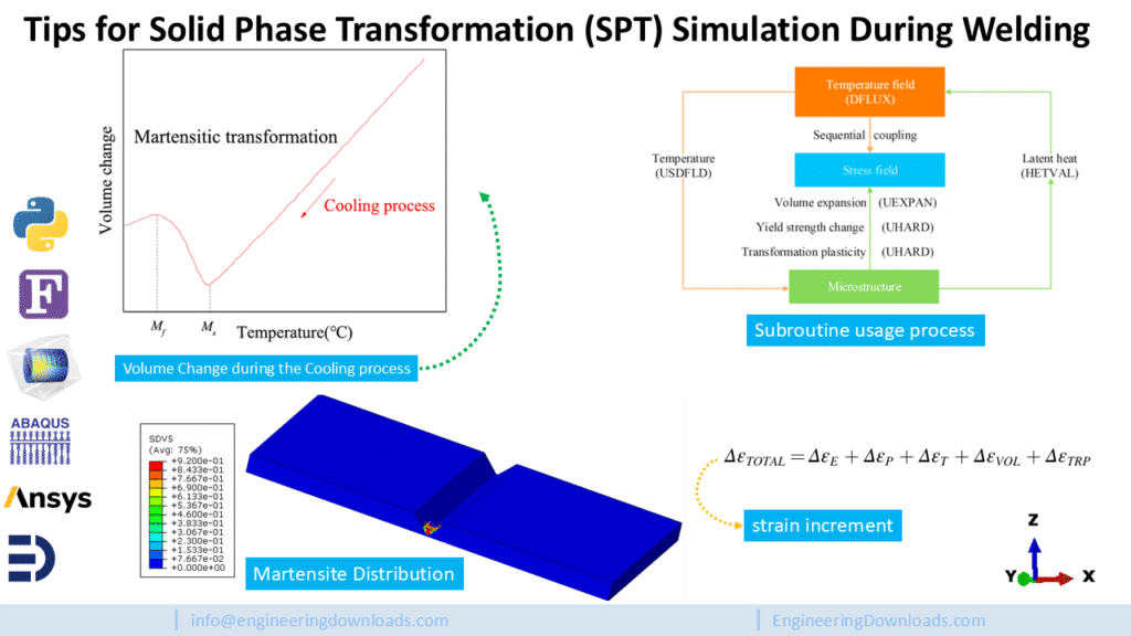
- Causes volume expansion when austenite transforms into martensite.
- Alters the yield strength of the material.
- Induces transformation plasticity as atoms rearrange.
Together, these effects change the stress distribution in the weld and heat-affected zone (HAZ). If ignored, simulations may underpredict or misrepresent residual stresses, leading to unsafe design assumptions.
This is why modern FEM simulations incorporate martensitic transformation into the temperature–microstructure–stress field calculations.

FEM Simulation of Phase Transformation During Welding
Traditional FEM welding simulations often focused only on thermal fields or mechanical stresses, neglecting microstructural changes. However, research shows that including SPT leads to much more accurate predictions.
The general simulation workflow involves:
- Thermal Analysis – Defining heat source models (like the double-ellipsoid heat source) to capture heat transfer during welding.
- Phase Transformation Modeling – Using formulas such as the Koistinen–Marburger equation to predict martensite formation based on temperature history.
- Coupled Field Analysis – Considering latent heat, volume changes, yield strength evolution, and transformation plasticity.
- Custom User Subroutines – Implementing additional physics in Abaqus via subroutines like DFLUX (heat input), USDFLD (phase fraction), HETVAL (latent heat), UEXPAN (volume expansion), and UHARD (strength change).
This multi-field coupling provides insights into residual stress distribution, crack susceptibility, and martensite fraction, which are critical for designing reliable welds in power plants, pressure vessels, and pipelines.
Practical FEM tips
- Use temperature-dependent material data
Load thermal conductivity, specific heat, elastic modulus, yield strength, and expansion coefficient as functions of temperature. Accurate property curves are the foundation — the phase change interacts directly with heat flow. - Simulate latent heat and phase fraction
Treat the martensitic transformation as a source/sink of heat (latent heat) and track the local martensite fraction. This alters the temperature history and therefore the stresses the weld sees. - Implement subroutines in Abaqus for full coupling
A set of user subroutines improves realism:
- DFLUX to apply the moving heat source (Goldak double-ellipsoid is a reliable choice).
- USDFLD (or an equivalent) to store martensite fraction as a field variable.
- HETVAL to inject latent heat where phase change happens.
- UEXPAN to apply volume expansion from transformation.
- UHARD to update yield strength as microstructure changes.
These subroutines let the thermal, microstructure, and mechanical fields talk to each other.
- Preheating — simulate different levels
Model preheating (e.g., 200 °C and other values) and compare residual stresses. Preheating reduces plastic strain during heating and widens the low-stress zone near the weld — an easy, effective process lever to reduce peak Mises stresses. - Optimize martensite start (Ms) temperature
Ms controls where martensite forms. In parametric runs you’ll often find a sweet spot: in studies on P91, an Ms near 325 °C gave much lower Mises stresses at the weld center. Try a small parameter sweep around your alloy’s estimated Ms to find the best tradeoff between hardness and residual stress. - Control interlayer temperature for multi-pass welding
Interpass/interlayer temperature affects how much martensite accumulates per pass. Raising it within limits can enlarge low-stress zones, increase beneficial longitudinal compressive residual stress, and reduce harmful transverse tensile stress. But don’t go too far — keep interlayer temperature below ~315 °C for P91 to avoid excessive hard, brittle martensite and cracking risk. - Mesh smart: refine where it counts
Use a fine mesh in and near the weld and HAZ where thermal gradients and phase changes are steep. Coarser mesh away from the weld saves CPU time without losing accuracy. Always run a mesh convergence check focused on stress peaks and martensite fraction. - Validate with experiments or literature
Compare temperature cycles, hardness maps, and residual stresses against published data or a few simple experiments. Validation builds confidence that the model predicts fatigue risk, hardness distribution, and residual stress correctly.
What microstructure changes mean for hardness & fatigue
- Hardness: Martensite → big hardness increase. The transformed zones will show higher hardness maps right after welding. This is why laser hardening or rapid cooling can triple local hardness in seconds: the lattice traps carbon and becomes strongly strained.
- Toughness & brittleness: More martensite generally lowers toughness and raises crack susceptibility. Harder is not always better for structural welds.
- Fatigue: Residual stress and local microstructure combine to set fatigue performance.
- Compressive residual stresses near the surface (or weld toe) are beneficial — they impede crack initiation and early growth.
- Tensile residual stresses and brittle martensitic zones are bad — they make cracks start sooner and grow faster.
Simulations that predict where martensite and tensile residual stress co-exist allow engineers to redesign welding procedures (preheat, interpass temp, post-weld heat treatment) to improve fatigue life.
- Transformation plasticity & volume change: These introduce strains and stress redistribution during cooling. They can be the difference between acceptable deformation and cracking in service.
Industrial applications & why this simulation matters
This coupled thermal–microstructure–mechanical simulation is directly useful for industries where high-temperature steels are critical:
- Power plants & boilers — P91 and similar creep-resistant steels are used in ultra-supercritical boilers and piping. Welding decisions here affect long-term creep and failure risk.
- Oil & gas pipelines and pressure vessels — Residual stress control reduces crack growth and leakage risk.
- Turbine and heat-exchanger fabrication — Welded joints face cyclic loading and thermal cycles; good welding practice increases service life.
- Repair welding & maintenance — Predicting how repairs will change local microstructure and stresses avoids repeat failures.
- Additive manufacturing & multi-pass fabrication — Each deposited layer has an interlayer temperature history — exactly the kind of problem this simulation helps manage.
In short: accurate phase-aware welding simulation lets engineers control hardness and residual stresses — and that directly reduces fatigue failures and extends component lifetime.
Download the validated model & codes (ready to use)
Good news — the validated FEM model and the user subroutine codes used to reproduce the paper’s results are available for download on Engineering Downloads. The package includes: Abaqus input files, example DFLUX/USDFLD/HETVAL/UEXPAN/UHARD subroutines, mesh templates, and a short README to run the cases (single-pass and multi-pass setups). Use these to jumpstart your own welding studies, adapt them to other alloys, or validate against your lab data.
About Saman Hosseini — quick intro
Saman Hosseini is a mechanical engineer and Abaqus specialist (freelancer and CEO of Engineering Downloads). He works on welding simulations, code development for Abaqus and ANSYS user subroutines, and teaches practical FEM workflows for industry engineers. Saman combines academic research experience with industrial practice to deliver ready-to-use simulation tools that save time and reduce welding risks.





2 Responses
clearly explained points for welding simulation . excelent
Thanks, dear Adil.
It’s nice to see you liked this blog.